YAMAHA WR 250F 2001 Notices Demploi (in French)
Manufacturer: YAMAHA, Model Year: 2001, Model line: WR 250F, Model: YAMAHA WR 250F 2001Pages: 686, PDF Size: 62.6 MB
Page 451 of 686
ENG
4 - 92
CARTER ET VILEBREQUIN
KURBELGEHÄUSE UND KURBELWELLE
CARTER E ALBERO MOTORE
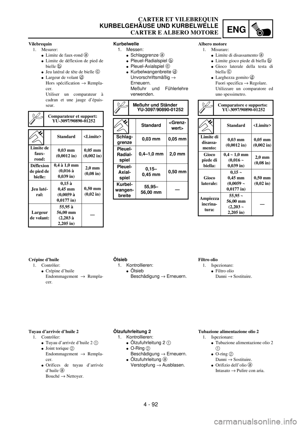
Kurbelwelle
1. Messen:
lSchlaggrenze a
lPleuel-Radialspiel b
lPleuel-Axialspiel c
lKurbelwangenbreite d
Unvorschriftsmäßig ®
Erneuern.
Meßuhr und Fühlerlehre
verwenden.
Meßuhr und Ständer
YU-3097/90890-01252
Standard
Schlag-
grenze0,03 mm 0,05 mm
Pleuel-
Radial-
spiel0,4–1,0 mm 2,0 mm
Pleuel-
Axial-
spiel0,15–
0,45 mm0,50 mm
Kurbel-
wangen-
breite55,95–
56,00 mm—
Ölsieb
1. Kontrollieren:
lÖlsieb
Beschädigung ® Erneuern.
Ölzufuhrleitung 2
1. Kontrollieren:
lÖlzufuhrleitung 2 1
lO-Ring 2
Beschädigung ® Erneuern.
lÖlzufuhrleitung a
Verstopfung ® Ausblasen. Vilebrequin
1. Mesurer:
lLimite de faux-rond a
lLimite de déflexion de pied de
bielle b
lJeu latéral de tête de bielle c
lLargeur de volant d
Hors spécification ® Rempla-
cer.
Utiliser un comparateur à
cadran et une jauge d’épais-
seur.
Comparateur et support:
YU-3097/90890-01252
Standard
Limite de
faux-
rond:0,03 mm
(0,0012 in)0,05 mm
(0,002 in)
Déflexion
de pied de
bielle:0,4 à 1,0 mm
(0,016 à
0,039 in)2,0 mm
(0,08 in)
Jeu laté-
ral:0,15 à
0,45 mm
(0,0059 à
0,0177 in)0,50 mm
(0,02 in)
Largeur
de volant:55,95 à
56,00 mm
(2,203 à
2,205 in)—
Crépine d’huile
1. Contrôler:
lCrépine d’huile
Endommagement ® Rempla-
cer.
Tuyau d’arrivée d’huile 2
1. Contrôler:
lTuyau d’arrivée d’huile 2 1
lJoint torique 2
Endommagement ® Rempla-
cer.
lOrifices de tuyau d’arrivée
d’huile a
Bouché ® Nettoyer.Albero motore
1. Misurare:
lLimite di disassamento a
lLimite gioco piede di biella b
lGioco laterale della testa di
biella c
lLarghezza gomito d
Fuori specifica ® Regolare.
Utilizzare un comparatore ed
uno spessimetro.
Comparatore e supporto:
YU-3097/90890-01252
Standard
Limite di
disassa-
mento:0,03 mm
(0,0012 in)0,05 mm
(0,002 in)
Gioco
piede di
biella:0,4 ~ 1,0 mm
(0,016 ~
0,039 in)2,0 mm
(0,08 in)
Gioco
laterale:0,15 ~
0,45 mm
(0,0059 ~
0,0177 in)0,50 mm
(0,02 in)
Ampiezza
incrina-
tura:55,95 ~
56,00 mm
(2,203 ~
2,205 in)—
Filtro olio
1. Ispezionare:
lFiltro olio
Danni ® Sostituire.
Tubazione alimentazione olio 2
1. Ispezionare:
lTubazione alimentazione olio 2
1
lO-ring 2
Danni ® Sostituire.
lOrifizio dell’olio a
Intasato ® Pulire con aria.
Page 452 of 686
![YAMAHA WR 250F 2001 Notices Demploi (in French) 4 - 93
ENGCRANKCASE AND CRANKSHAFT
EC4N5000
ASSEMBLY AND INSTALLATION
Crankcase bearing
1. Install:
lBearing
lBearing stopper
lScrew (bearing stopper)
lScrew [bearing stopper (crankshaft)] 1
To left YAMAHA WR 250F 2001 Notices Demploi (in French) 4 - 93
ENGCRANKCASE AND CRANKSHAFT
EC4N5000
ASSEMBLY AND INSTALLATION
Crankcase bearing
1. Install:
lBearing
lBearing stopper
lScrew (bearing stopper)
lScrew [bearing stopper (crankshaft)] 1
To left](/img/51/52339/w960_52339-451.png)
4 - 93
ENGCRANKCASE AND CRANKSHAFT
EC4N5000
ASSEMBLY AND INSTALLATION
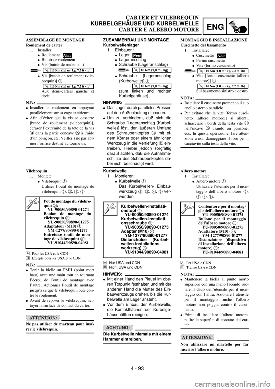
Crankcase bearing
1. Install:
lBearing
lBearing stopper
lScrew (bearing stopper)
lScrew [bearing stopper (crankshaft)] 1
To left and right crankcase.
NOTE:
lInstall the bearing by pressing its outer race
parallel.
lTo prevent the screw [bearing stopper
(crankshaft)] from becoming loose, crush the
screw head periphery a into the concave b
using a punch etc. In so doing, take care not
to damage the screwdriver receiving hole in
the screw head.
T R..10 Nm (1.0 m · kg, 7.2 ft · lb)1
a
b
T R..10 Nm (1.0 m · kg, 7.2 ft · lb)
Crankshaft
1. Install:
lCrankshaft 1
Use the crankshaft installing tool 2, 3,
4, 5.
For USA and CDN
õExcept for USA and CDN
NOTE:
lHold the connecting rod at top dead center
with one hand while turning the nut of the
installing tool with the other. Operate the
installing tool until the crankshaft bottoms
against the bearing.
lBefore installing the crankshaft, clean the
contacting surface of crankcase.
CAUTION:
Do not use a hammer to drive in the crank-
shaft.
Crankshaft installing pot 2:
YU-90050/90890-01274
Crankshaft installing bolt 3:
YU-90050/90890-01275
Adapter (M10) 4:
YM-1277/90890-01277
Spacer (crankshaft installer) 5:
YU-91044/90890-04081
õ
Page 453 of 686
ENG
4 - 93
CARTER ET VILEBREQUIN
KURBELGEHÄUSE UND KURBELWELLE
CARTER E ALBERO MOTORE
ZUSAMMENBAU UND MONTAGE
Kurbelwellenlager
1. Einbauen:
lLager
lLageranschlag
lSchraube (Lageranschlag)
lSchraube [Lageranschlag
(Kurbelwelle)]
1
(zum linken und rechten
Kurbelgehäuse)
HINWEIS:
lDas Lager durch paralleles Pressen
auf den Außenlaufring einbauen.
lUm zu verhindern, daß sich die
Schraube [Lageranschlag (Kurbel-
welle)] löst, den äußeren Umfang
des Schraubenkopfes a mit ei-
nem Körner oder einem ähnlichen
Werkzeug in die Vertiefung b ein-
treiben. Hierbei jedoch sorgfältig
darauf achten, daß die Aufnahme-
schlitze des Schraubenkopfes da-
bei nicht beschädigt wird.
T R..10 Nm (1,0 m · kg)
T R..10 Nm (1,0 m · kg)
Kurbelwelle
1. Montieren:
lKurbelwelle 1
Das Kurbelwellen- Einbau-
werkzeug 2, 3, 4, 5 ver-
wenden.
Nur USA und CDN
õNicht USA und CDN
HINWEIS:
lMit einer Hand den Pleuel im obe-
ren Totpunkt festhalten und mit der
anderen Hand die Mutter des Ein-
bauwerkzeugs drehen, bis die Kur-
belwelle am Lager ansteht.
lVor dem Einbau der Kurbelwelle,
die Kontaktflächen der Kurbelge-
häusehälften reinigen.
ACHTUNG:
Die Kurbelwelle niemals mit einem
Hammer eintreiben.
Kurbelwellen-Installati-
onstopf 2
YU-90050/90890-01274
Kurbelwellen-Installati-
onsschraube 3:
YU-90050/90890-01275
Adapter (M10) 4
YM-1277/90890-01277
Distanzhülse (Kurbel-
wellen-Installations-
werkzeug) 5
YU-91044/90890-04081
ASSEMBLAGE ET MONTAGE
Roulement de carter
1. Installer:
lRoulement
lButoir de roulement
lVis (butoir de roulement)
lVis [butoir de roulement (vile-
brequin)] 1
Aux demi-carters gauche et
droit.
N.B.:
lInstaller le roulement en appuyant
parallèlement sur sa cage extérieure.
lAfin d’éviter que la vis se desserre
[butée de roulement (vilebrequin)],
écraser l’extrémité de la tête de la vis
a dans la partie concave b à l’aide
d’un poinçon, etc. Veiller à ne pas abî-
mer l’orifice destiné au tournevis.
T R..10 Nm (1,0 m · kg, 7,2 ft · lb)
T R..10 Nm (1,0 m · kg, 7,2 ft · lb)
Vilebrequin
1. Monter:
lVilebrequin 1
Utiliser l’outil de montage de
vilebrequin 2, 3, 4, 5.
Pour les USA et le CDN
õExcepté pour les USA et le CDN
N.B.:
lTenir la bielle au PMH (point mort
haut) avec une main tout en tournant
l’écrou de l’outil de montage avec
l’autre. Actionner l’outil de montage
jusqu’a ce que le vilebrequin bute con-
tre le roulement.
lAvant de reposer le vilebrequin, net-
toyer la surface de contact du carter.
ATTENTION:
Ne pas utiliser de marteau pour insé-
rer le vilebrequin.
Pot de montage du vilebre-
quin 2:
YU-90050/90890-01274
Boulon de montage du
vilebrequin 3:
YU-90050/90890-01275
Adaptateur (M10) 4:
YM-1277/90890-01277
Entretoise (outil de mon-
tage de vilebrequin) 5:
YU-91044/90890-04081
MONTAGGIO E INSTALLAZIONE
Cuscinetto del basamento
1. Installare:
lCuscinetto
lFermo cuscinetto
lVite (fermo cuscinetto)
lVite [fermo cuscinetto (albero
motore)] 1
Sul basamento sinistro e destro.
NOTA:
lInstallare il cuscinetto premendo il suo
anello esterno parallelo.
lPer evitare che la vite [fermo cusci-
netto (albero motore)] si allenti,
schiacciare i bordi della testa vite a
nell’incavo b usando un punzone,
ecc. In questa operazione, fare atten-
zione a non danneggiare il foro per il
cacciavite sulla testa della vite.
T R..10 Nm (1,0 m · kg, 7,2 ft · lb)
T R..10 Nm (1,0 m · kg, 7,2 ft · lb)
Albero motore
1. Installare:
lAlbero motore 1
Utilizzare l’utensile per il mon-
taggio dell’albero motore 2,
3, 4, 5.
Per USA e CDN
õTranne USA e CDN
NOTA:
lMantenere la biella al punto morto
superiore con una mano facendo ruo-
tare il dado dell’utensile per il mon-
taggio con l’altra. Azionare l’utensile
per il montaggio finché l’albero
motore non poggia contro il cusci-
netto.
lPrima di installare l’albero motore,
pulire le superfici di contatto del car-
ter.
ATTENZIONE:
Non utilizzare un martello per far
inserire l’albero motore.
Contenitore per il montag-
gio dell’albero motore 2:
YU-90050/90890-01274
Bullone per il montaggio
dell’albero motore 3:
YU-90050/90890-01275
Adattatore (M10) 4:
YM-1277/90890-01277
Distanziatore (dispositivo
di installazione dell’albero
motore) 5:
YU-91044/90890-04081
Page 454 of 686
4 - 94
ENGCRANKCASE AND CRANKSHAFT
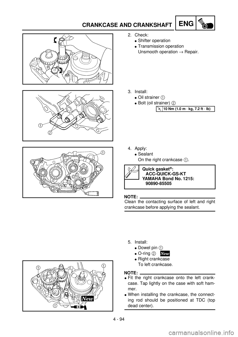
2. Check:
lShifter operation
lTransmission operation
Unsmooth operation ® Repair.
3. Install:
lOil strainer 1
lBolt (oil strainer) 2
T R..10 Nm (1.0 m · kg, 7.2 ft · lb)
4. Apply:
lSealant
On the right crankcase 1.
NOTE:
Clean the contacting surface of left and right
crankcase before applying the sealant.
5. Install:
lDowel pin 1
lO-ring 2
lRight crankcase
To left crankcase.
NOTE:
lFit the right crankcase onto the left crank-
case. Tap lightly on the case with soft ham-
mer.
lWhen installing the crankcase, the connect-
ing rod should be positioned at TDC (top
dead center).
Quick gasket®:
ACC-QUICK-GS-KT
YAMAHA Bond No. 1215:
90890-85505
Page 455 of 686
ENG
4 - 94
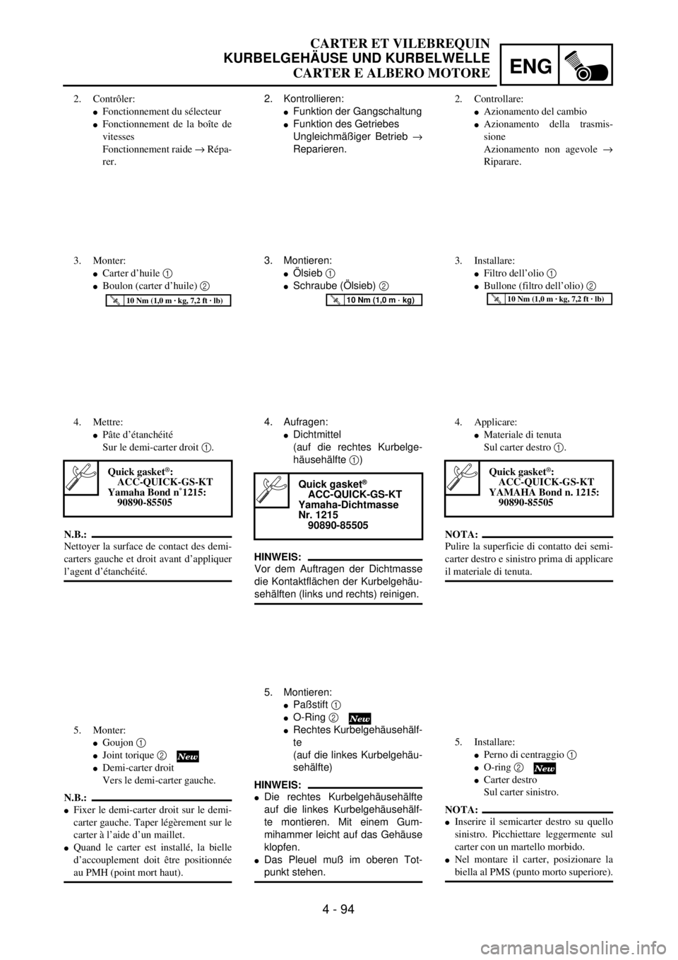
2. Kontrollieren:
lFunktion der Gangschaltung
lFunktion des Getriebes
Ungleichmäßiger Betrieb ®
Reparieren.
3. Montieren:
lÖlsieb 1
lSchraube (Ölsieb) 2
T R..10 Nm (1,0 m · kg)
4. Aufragen:
lDichtmittel
(auf die rechtes Kurbelge-
häusehälfte 1)
HINWEIS:
Vor dem Auftragen der Dichtmasse
die Kontaktflächen der Kurbelgehäu-
sehälften (links und rechts) reinigen.
5. Montieren:
lPaßstift 1
lO-Ring 2
lRechtes Kurbelgehäusehälf-
te
(auf die linkes Kurbelgehäu-
sehälfte)
HINWEIS:
lDie rechtes Kurbelgehäusehälfte
auf die linkes Kurbelgehäusehälf-
te montieren. Mit einem Gum-
mihammer leicht auf das Gehäuse
klopfen.
lDas Pleuel muß im oberen Tot-
punkt stehen.
Quick gasket®
ACC-QUICK-GS-KT
Yamaha-Dichtmasse
Nr. 1215
90890-85505
2. Contrôler:
lFonctionnement du sélecteur
lFonctionnement de la boîte de
vitesses
Fonctionnement raide ® Répa-
rer.
3. Monter:
lCarter d’huile 1
lBoulon (carter d’huile) 2
T R..10 Nm (1,0 m · kg, 7,2 ft · lb)
4. Mettre:
lPâte d’étanchéité
Sur le demi-carter droit 1.
N.B.:
Nettoyer la surface de contact des demi-
carters gauche et droit avant d’appliquer
l’agent d’étanchéité.
5. Monter:
lGoujon 1
lJoint torique 2
lDemi-carter droit
Vers le demi-carter gauche.
N.B.:
lFixer le demi-carter droit sur le demi-
carter gauche. Taper légèrement sur le
carter à l’aide d’un maillet.
lQuand le carter est installé, la bielle
d’accouplement doit être positionnée
au PMH (point mort haut).
Quick gasket®:
ACC-QUICK-GS-KT
Yamaha Bond n˚1215:
90890-85505
2. Controllare:
lAzionamento del cambio
lAzionamento della trasmis-
sione
Azionamento non agevole ®
Riparare.
3. Installare:
lFiltro dell’olio 1
lBullone (filtro dell’olio) 2
T R..10 Nm (1,0 m · kg, 7,2 ft · lb)
4. Applicare:
lMateriale di tenuta
Sul carter destro 1.
NOTA:
Pulire la superficie di contatto dei semi-
carter destro e sinistro prima di applicare
il materiale di tenuta.
5. Installare:
lPerno di centraggio 1
lO-ring 2
lCarter destro
Sul carter sinistro.
NOTA:
lInserire il semicarter destro su quello
sinistro. Picchiettare leggermente sul
carter con un martello morbido.
lNel montare il carter, posizionare la
biella al PMS (punto morto superiore).
Quick gasket®:
ACC-QUICK-GS-KT
YAMAHA Bond n. 1215:
90890-85505
CARTER ET VILEBREQUIN
KURBELGEHÄUSE UND KURBELWELLE
CARTER E ALBERO MOTORE
Page 456 of 686

4 - 95
ENGCRANKCASE AND CRANKSHAFT
6. Tighten:
lHose guide 1
lClutch cable holder 2
lBolt (crankcase) 3
NOTE:
Tighten the crankcase tightening bolts in
stage, using a crisscross pattern.
T R..12 Nm (1.2 m · kg, 8.7 ft · lb)
7. Install:
lOil delivery pipe 2 1
lO-ring 2
lBolt (oil delivery pipe 2) 3
NOTE:
Apply the lithium soap base grease on the O-
rings.
T R..10 Nm (1.0 m · kg, 7.2 ft · lb)
8. Install:
lTiming chain 1
lTiming chain guide (intake side) 2
lBolt (timing chain guide) 3
9. Remove:
lSealant
Forced out on the cylinder mating sur-
face.
10. Apply:
lEngine oil
To the crank pin, bearing and oil deliv-
ery hole.
11. Check:
lCrankshaft and transmission operation.
Unsmooth operation ® Repair.
T R..10 Nm (1.0 m · kg, 7.2 ft · lb)
Page 457 of 686
ENG
4 - 95
6. Montieren:
lKabelführung 1
lKupplungszug-Halterung 2
lSchraube (Kurbelgehäuse)
3
HINWEIS:
Die Kurbelgehäuse-Schrauben in
stufenweise und über Kreuz festzie-
hen.
T R..12 Nm (1,2 m · kg)
7. Montieren:
lÖlzufuhrleitung 2 1
lO-Ring 2
lSchraube (Ölzufuhrleitung
2) 3
HINWEIS:
Lithiumfett auf den O-Ringe aufra-
gen.
T R..10 Nm (1,0 m · kg)
8. Montieren:
lSteuerkette 1
lSteuerkettenschiene (hin-
ten) 2
lSchraube (Steuerketten-
schiene) 3
9. Entfernen:
lDichtmittel
(von der Zylinderpaßfläche
getrieben)
10. Auftragen:
lMotoröl
(auf Kurbelzapfen, Lager
und Ölzufuhrloch)
11. Kontrollieren:
lKurbelwelle und Getriebe
(Leichtgängigkeit)
Schwergängigkeit ®
Instand setzen.
T R..10 Nm (1,0 m · kg)
6. Monter:
lGuide de durit 1
lSupport de câble d’embrayage
2
lBoulon (carter) 3
N.B.:
Serrer les boulons de serrage de carter
par étape en suivant un ordre entrecroisé.
T R..12 Nm (1,2 m · kg, 8,7 ft · lb)
7. Monter:
lTuyau d’arrivée d’huile 2 1
lJoint torique 2
lBoulon (tuyau d’arrivée
d’huile 2) 3
N.B.:
Enduire les joints toriqus de graisse à
base de savon au lithium.
T R..10 Nm (1,0 m · kg, 7,2 ft · lb)
8. Monter:
lChaîne de distribution 1
lGuide de chaîne de distribution
(côté admission) 2
lBoulon (guide de chaîne de
distribution) 3
9. Déposer:
lAgent d’étanchéité
Sorti sur la surface usinée du
cylindre.
10. Appliquer:
lHuile moteur
Sur la goupille de carter, le rou-
lement et l’orifice de sortie
d’huile.
11. Contrôler:
lFonctionnement du vilebrequin
et de la transmission
Fonctionnement irrégulier ®
Réparer.
T R..10 Nm (1,0 m · kg, 7,2 ft · lb)
6. Serrare:
lGuida del flessibile 1
lSupporto cavo frizione 2
lBullone (carter) 3
NOTA:
Serrare i bulloni del carter in fasi, in
maniera incrociata.
T R..12 Nm (1,2 m · kg, 8,7 ft · lb)
7. Installare:
lTubazione alimentazione olio 2
1
lO-ring 2
lBullone (tubazione alimenta-
zione olio 2) 3
NOTA:
Applicare grasso a base di sapone di litio
sugli O-ring.
T R..10 Nm (1,0 m · kg, 7,2 ft · lb)
8. Installare:
lCatena di distribuzione 1
lGuida catena di distribuzione
(lato aspirazione) 2
lBullone (guida catena di distri-
buzione) 3
9. Rimuovere:
lMateriale di tenuta
Forzato sulla superficie di
accoppiamento del cilindro.
10. Applicare:
lOlio motore
Al perno del gomito, al cusci-
netto e al foro di alimentazione
dell’olio.
11. Controllare:
lAzionamento albero motore
trasmissione.
Azionamento non agevole ®
Riparare.
T R..10 Nm (1,0 m · kg, 7,2 ft · lb)
CARTER ET VILEBREQUIN
KURBELGEHÄUSE UND KURBELWELLE
CARTER E ALBERO MOTORE
Page 458 of 686
4 - 96
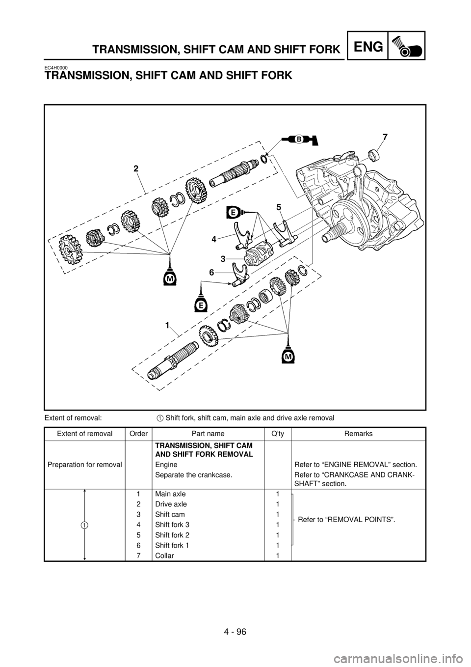
ENGTRANSMISSION, SHIFT CAM AND SHIFT FORK
EC4H0000
TRANSMISSION, SHIFT CAM AND SHIFT FORK
Extent of removal:1 Shift fork, shift cam, main axle and drive axle removal
Extent of removal Order Part name Q’ty Remarks
TRANSMISSION, SHIFT CAM
AND SHIFT FORK REMOVAL
Preparation for removal Engine Refer to “ENGINE REMOVAL” section.
Separate the crankcase. Refer to “CRANKCASE AND CRANK-
SHAFT” section.
1 Main axle 1
Refer to “REMOVAL POINTS”. 2 Drive axle 1
3 Shift cam 1
4 Shift fork 3 1
5 Shift fork 2 1
6 Shift fork 1 1
7 Collar 1
1
Page 459 of 686
4 - 96
ENG
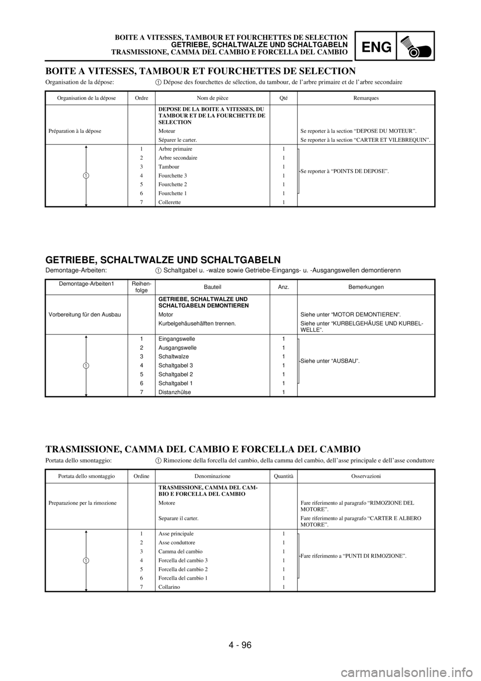
BOITE A VITESSES, TAMBOUR ET FOURCHETTES DE SELECTION
GETRIEBE, SCHALTWALZE UND SCHALTGABELN
TRASMISSIONE, CAMMA DEL CAMBIO E FORCELLA DEL CAMBIO
GETRIEBE, SCHALTWALZE UND SCHALTGABELN
Demontage-Arbeiten:1 Schaltgabel u. -walze sowie Getriebe-Eingangs- u. -Ausgangswellen demontierenn
Demontage-Arbeiten1 Reihen-
folgeBauteil Anz. Bemerkungen
GETRIEBE, SCHALTWALZE UND
SCHALTGABELN DEMONTIEREN
Vorbereitung für den Ausbau Motor Siehe unter “MOTOR DEMONTIEREN”.
Kurbelgehäusehälften trennen. Siehe unter “KURBELGEHÄUSE UND KURBEL-
WELLE”.
1 Eingangswelle 1
Siehe unter “AUSBAU”. 2 Ausgangswelle 1
3 Schaltwalze 1
4 Schaltgabel 3 1
5 Schaltgabel 2 1
6 Schaltgabel 1 1
7 Distanzhülse 1
1
BOITE A VITESSES, TAMBOUR ET FOURCHETTES DE SELECTION
Organisation de la dépose:1 Dépose des fourchettes de sélection, du tambour, de l’arbre primaire et de l’arbre secondaire
Organisation de la dépose Ordre Nom de pièce Qté Remarques
DEPOSE DE LA BOITE A VITESSES, DU
TAMBOUR ET DE LA FOURCHETTE DE
SELECTION
Préparation à la dépose Moteur Se reporter à la section “DEPOSE DU MOTEUR”.
Séparer le carter. Se reporter à la section “CARTER ET VILEBREQUIN”.
1 Arbre primaire 1
Se reporter à “POINTS DE DEPOSE”. 2 Arbre secondaire 1
3 Tambour 1
4 Fourchette 3 1
5 Fourchette 2 1
6 Fourchette 1 1
7 Collerette 1
1
TRASMISSIONE, CAMMA DEL CAMBIO E FORCELLA DEL CAMBIO
Portata dello smontaggio:1 Rimozione della forcella del cambio, della camma del cambio, dell’asse principale e dell’asse conduttore
Portata dello smontaggio Ordine Denominazione Quantità Osservazioni
TRASMISSIONE, CAMMA DEL CAM-
BIO E FORCELLA DEL CAMBIO
Preparazione per la rimozione Motore Fare riferimento al paragrafo “RIMOZIONE DEL
MOTORE”.
Separare il carter. Fare riferimento al paragrafo “CARTER E ALBERO
MOTORE”.
1 Asse principale 1
Fare riferimento a “PUNTI DI RIMOZIONE”. 2 Asse conduttore 1
3 Camma del cambio 1
4 Forcella del cambio 3 1
5 Forcella del cambio 2 1
6 Forcella del cambio 1 1
7 Collarino 1
1
Page 460 of 686
4 - 97
ENGTRANSMISSION, SHIFT CAM AND SHIFT FORK
EC4H3000
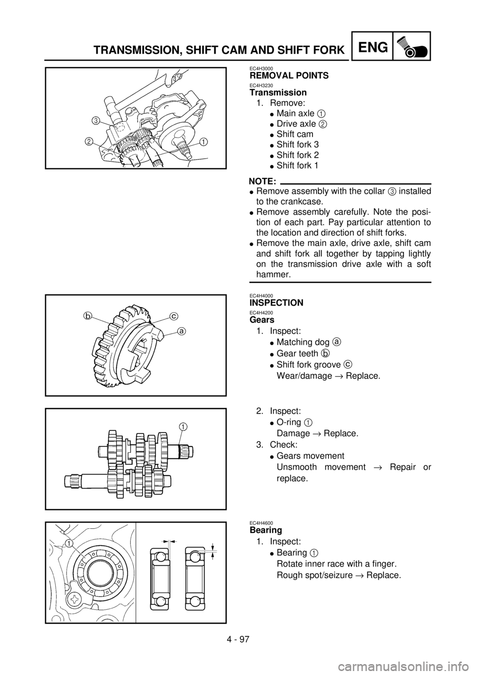
REMOVAL POINTS
EC4H3230
Transmission
1. Remove:
lMain axle 1
lDrive axle 2
lShift cam
lShift fork 3
lShift fork 2
lShift fork 1
NOTE:
lRemove assembly with the collar 3 installed
to the crankcase.
lRemove assembly carefully. Note the posi-
tion of each part. Pay particular attention to
the location and direction of shift forks.
lRemove the main axle, drive axle, shift cam
and shift fork all together by tapping lightly
on the transmission drive axle with a soft
hammer.
EC4H4000
INSPECTION
EC4H4200
Gears
1. Inspect:
lMatching dog a
lGear teeth b
lShift fork groove c
Wear/damage ® Replace.
2. Inspect:
lO-ring 1
Damage ® Replace.
3. Check:
lGears movement
Unsmooth movement ® Repair or
replace.
EC4H4600
Bearing
1. Inspect:
lBearing 1
Rotate inner race with a finger.
Rough spot/seizure ® Replace.