YAMAHA WR 250F 2006 Manuale de Empleo (in Spanish)
Manufacturer: YAMAHA, Model Year: 2006, Model line: WR 250F, Model: YAMAHA WR 250F 2006Pages: 900, tamaño PDF: 23.77 MB
Page 781 of 900

6 - 18
–+ELEC
ZÜNDSPULE KONTROLLIEREN
1. Den Stecker von der Zündspule
abziehen.
2. Kontrollieren:
•Primärwicklungs-Widerstand
Nicht nach Vorgabe
→ Erneu-
ern.
Messkabel (+) → Orange 1
Messkabel (–) → Schwarz 2
Primärwick-
lungs Wider-
standMessgerät-
Wahlschal-
ter
0,08–0,10 Ω
bei 20 °C
(68 °F) Ω × 1
3. Kontrollieren:
•Sekundärwicklungs-Wider-
stand
Nicht nach Vorgabe
→ Erneu-
ern.
Messkabel (+) → Orange 1
Messkabel (–) →
Zündkerzen-Kontakt 2
Sekundärwick-
lungs Wider-
standMessgerät-
Wahlschal-
ter
4,6–6,8 kΩ bei
20 °C (68 °F)kΩ × 1
4. Kontrollieren:
•versiegelten Teil
a der Zünd-
spule
•Zündkerzen-Kontaktstift
b
•Gewindeteil
c der Zündkerze
Verschlissen
→ Erneuern.CONTROLLO BOBINA DI
ACCENSIONE
1. Togliere il coperchio della bobina di
accensione.
2. Controllare:
Resistenza bobina primaria
Non conforme alle specifiche →
Sostituire.
Tester (+) cavo →
Cavo arancione 1
Tester (–) cavo → Cavo nero 2
Resistenza
bobina primariaPosizione
del selettore
del tester
0,08 ~ 0,10 Ω a
20 °C (68 °F)Ω × 1
3. Controllare:
Resistenza bobina secondaria
Non conforme alle specifiche →
Sostituire.
Tester (+) cavo →
Cavo arancione 1
Tester (–) cavo →
Terminale candela di accensione 2
Resistenza
bobina
secondariaPosizione
del selettore
del tester
4,6 ~ 6,8 kΩ a
20 °C (68 °F)kΩ × 1
4. Controllare:
Porzione sigillata della bobina di
accensione a
Spinotto del terminale candela di
accensione b
Porzione avvitata della candela di
accensione c
Usura → Sostituire.COMPROBACIÓN DE LA BOBINA
DE ENCENDIDO
1. Retire la tapa de la bobina de
encendido.
2. Comprobar:
•Resistencia de la bobina pri-
maria
Fuera del valor especificado
→ Cambiar.
Comprobador (+) cable →
Cable naranja 1
Comprobador (–) cable →
Cable negro 2
Resistencia de
la bobina
primariaPosición
del selector
del com-
probador
0,08 ~ 0,10 Ω a
20 °C (68 °F)Ω × 1
3. Comprobar:
•Resistencia de la bobina
secundaria
Fuera del valor especificado
→ Cambiar.
Comprobador (+) cable →
Cable naranja 1
Comprobador (–) cable →
Terminal de la bujía 2
Resistencia de
la bobina
secundariaPosición
del selector
del com-
probador
4,6 ~ 6,8 kΩ a
20 °C (68 °F)kΩ × 1
4. Comprobar:
•Parte sellada da la bobina de
encendido
a
•Clavija del terminal de la bujía
b
•Parte roscada de la bujía
c
Desgaste
→ Cambiar.
ZÜNDSYSTEM
IMPIANTO DI ACCENSIONE
SISTEMA DE ENCENDIDO
Page 782 of 900
6 - 19
–+ELECIGNITION SYSTEM
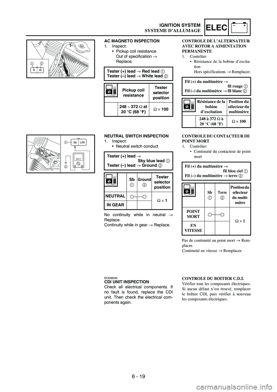
AC MAGNETO INSPECTION
1. Inspect:
•Pickup coil resistance
Out of specification
→
Replace.
Tester (+) lead →
Red lead 1
Tester (–) lead →
White lead 2
Pickup coil
resistanceTester
selector
position
248 ~ 372 Ω
at
20 °C (68 °F)Ω
×
100
RW
12
NEUTRAL SWITCH INSPECTION
1. Inspect:
•Neutral switch conduct
No continuity while in neutral
→
Replace.
Continuity while in gear
→ Replace. Tester (+) lead →
Sky blue lead 1
Tester (–) lead →
Ground 2
Sb
1
Ground
2
Tester
selector
position
NEUTRAL
Ω
×
1
IN GEAR
–+ Ω×1
1
2L/W Sb
EC628000CDI UNIT INSPECTION
Check all electrical components. If
no fault is found, replace the CDI
unit. Then check the electrical com-
ponents again.CONTROLE DE L’ALTERNATEUR
AVEC ROTOR A AIMENTATION
PERMANENTE
1. Contrôler:
Résistance de la bobine d’excita-
tion
Hors spécifications → Remplacer.
Fil (+) du multimètre →
fil rouge 1
Fil (–) du multimètre → fil blanc 2
Résistance de la
bobine
d’excitationPosition du
sélecteur du
multimètre
248 à 372 Ω à
20 °C (68 °F)Ω × 100
CONTROLE DU CONTACTEUR DE
POINT MORT
1. Contrôler:
Continuité du contacteur de point
mort
Pas de continuité au point mort → Rem-
placer.
Continuité en vitesse → Remplacer. Fil (+) du multimètre →
fil bleu ciel 1
Fil (–) du multimètre → terre 2
Sb
1 Terre
2
Position du
sélecteur
du multi-
mètre
POINT
MORT
Ω × 1
EN
VITESSE
CONTROLE DU BOITIER C.D.I.
Vérifier tous les composants électriques.
Si aucun défaut n’est trouvé, remplacer
le boîtier CDI, puis vérifier à nouveau
les composants électriques.
SYSTEME D’ALLUMAGE
Page 783 of 900
6 - 20
–+ELEC
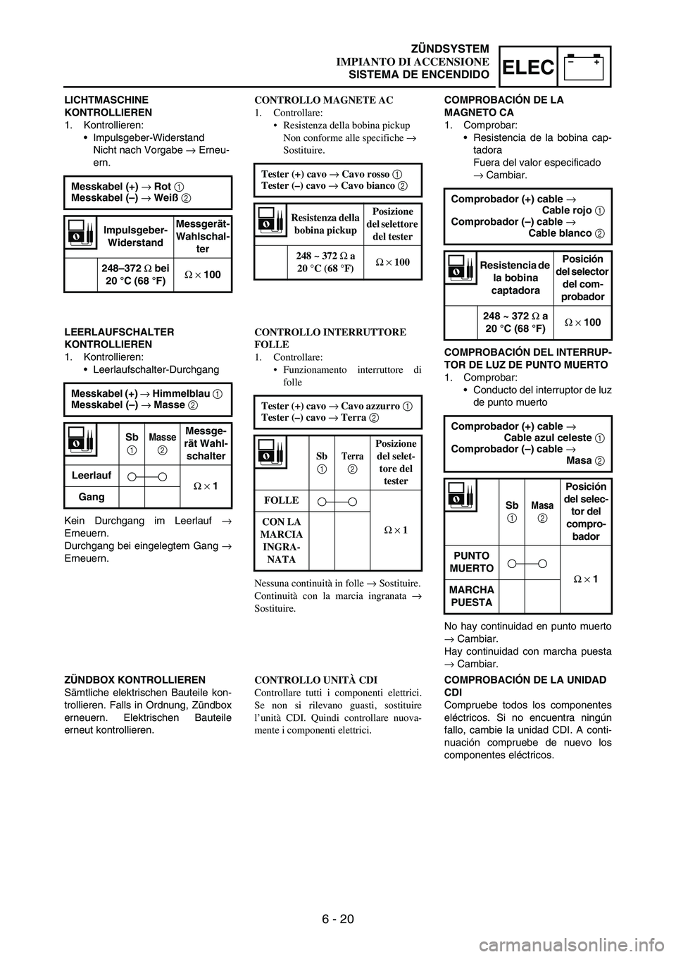
LICHTMASCHINE
KONTROLLIEREN
1. Kontrollieren:
•Impulsgeber-Widerstand
Nicht nach Vorgabe
→ Erneu-
ern.
Messkabel (+) → Rot 1
Messkabel (–) → Weiß 2
Impulsgeber-
WiderstandMessgerät-
Wahlschal-
ter
248–372 Ω bei
20 °C (68 °F)Ω × 100
LEERLAUFSCHALTER
KONTROLLIEREN
1. Kontrollieren:
•Leerlaufschalter-Durchgang
Kein Durchgang im Leerlauf
→
Erneuern.
Durchgang bei eingelegtem Gang
→
Erneuern.Messkabel (+) → Himmelblau 1
Messkabel (–) → Masse 2
Sb
1 Masse
2
Messge-
rät Wahl-
schalter
Leerlauf
Ω × 1
Gang
ZÜNDBOX KONTROLLIEREN
Sämtliche elektrischen Bauteile kon-
trollieren. Falls in Ordnung, Zündbox
erneuern. Elektrischen Bauteile
erneut kontrollieren.CONTROLLO MAGNETE AC
1. Controllare:
Resistenza della bobina pickup
Non conforme alle specifiche →
Sostituire.
Tester (+) cavo → Cavo rosso 1
Tester (–) cavo → Cavo bianco 2
Resistenza della
bobina pickupPosizione
del selettore
del tester
248 ~ 372 Ω a
20 °C (68 °F)Ω × 100
CONTROLLO INTERRUTTORE
FOLLE
1. Controllare:
Funzionamento interruttore di
folle
Nessuna continuità in folle → Sostituire.
Continuità con la marcia ingranata →
Sostituire.Tester (+) cavo → Cavo azzurro 1
Tester (–) cavo → Terra 2
Sb
1 Terra
2
Posizione
del selet-
tore del
tester
FOLLE
Ω × 1 CON LA
MARCIA
INGRA-
NATA
CONTROLLO UNITÀ CDI
Controllare tutti i componenti elettrici.
Se non si rilevano guasti, sostituire
l’unità CDI. Quindi controllare nuova-
mente i componenti elettrici.COMPROBACIÓN DE LA
MAGNETO CA
1. Comprobar:
•Resistencia de la bobina cap-
tadora
Fuera del valor especificado
→ Cambiar.
COMPROBACIÓN DEL INTERRUP-
TOR DE LUZ DE PUNTO MUERTO
1. Comprobar:
•Conducto del interruptor de luz
de punto muerto
No hay continuidad en punto muerto
→ Cambiar.
Hay continuidad con marcha puesta
→ Cambiar. Comprobador (+) cable →
Cable rojo 1
Comprobador (–) cable →
Cable blanco 2
Resistencia de
la bobina
captadoraPosición
del selector
del com-
probador
248 ~ 372 Ω a
20 °C (68 °F)Ω × 100
Comprobador (+) cable →
Cable azul celeste 1
Comprobador (–) cable →
Masa 2
Sb
1 Masa
2
Posición
del selec-
tor del
compro-
bador
PUNTO
MUERTO
Ω × 1
MARCHA
PUESTA
COMPROBACIÓN DE LA UNIDAD
CDI
Compruebe todos los componentes
eléctricos. Si no encuentra ningún
fallo, cambie la unidad CDI. A conti-
nuación compruebe de nuevo los
componentes eléctricos.
ZÜNDSYSTEM
IMPIANTO DI ACCENSIONE
SISTEMA DE ENCENDIDO
Page 784 of 900
6 - 21
–+ELECELECTRIC STARTING SYSTEM
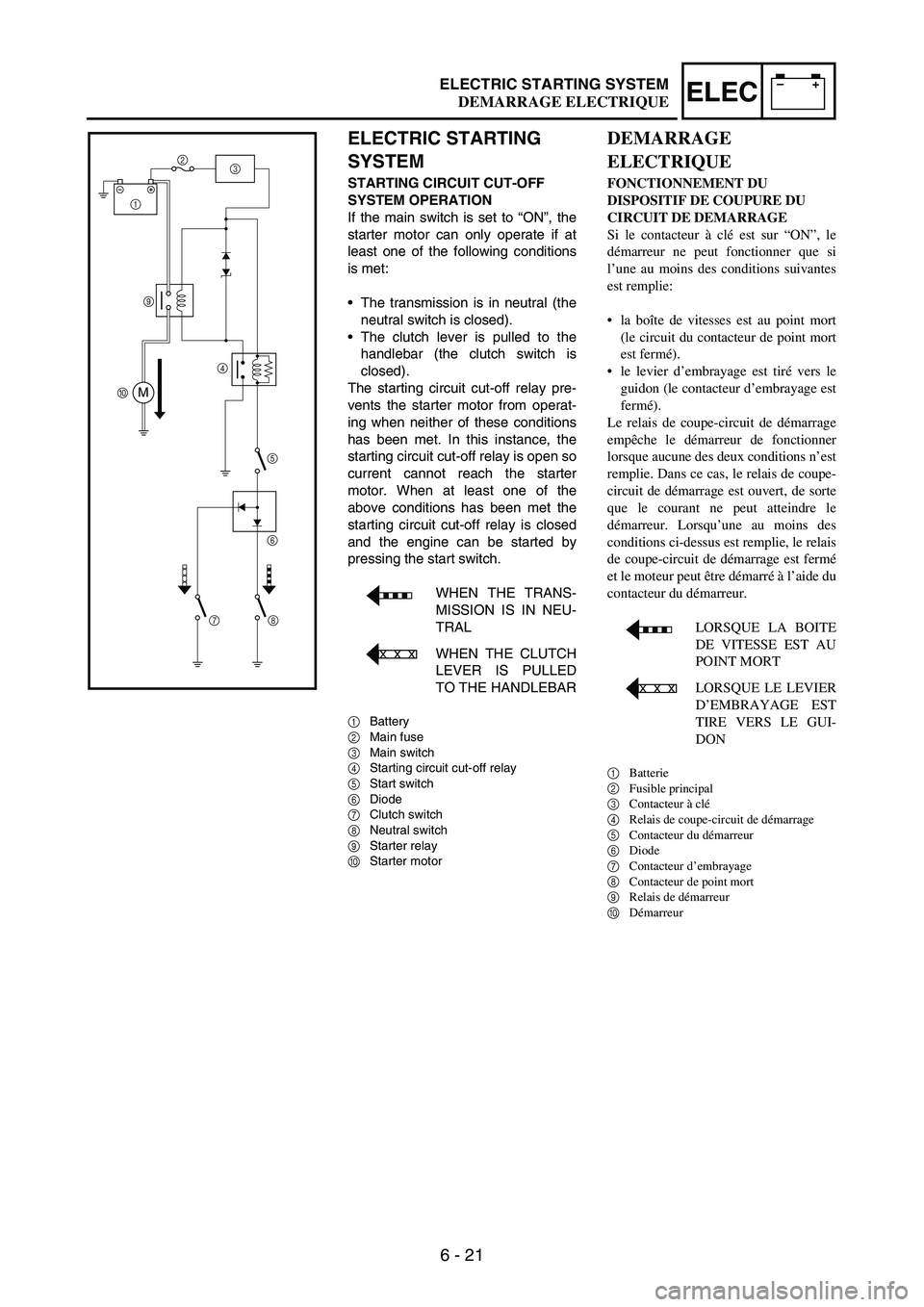
ELECTRIC STARTING
SYSTEM
STARTING CIRCUIT CUT-OFF
SYSTEM OPERATION
If the main switch is set to “ON”, the
starter motor can only operate if at
least one of the following conditions
is met:
•The transmission is in neutral (the
neutral switch is closed).
•The clutch lever is pulled to the
handlebar (the clutch switch is
closed).
The starting circuit cut-off relay pre-
vents the starter motor from operat-
ing when neither of these conditions
has been met. In this instance, the
starting circuit cut-off relay is open so
current cannot reach the starter
motor. When at least one of the
above conditions has been met the
starting circuit cut-off relay is closed
and the engine can be started by
pressing the start switch.
WHEN THE TRANS-
MISSION IS IN NEU-
TRAL
WHEN THE CLUTCH
LEVER IS PULLED
TO THE HANDLEBAR
1Battery
2Main fuse
3Main switch
4Starting circuit cut-off relay
5Start switch
6Diode
7Clutch switch
8Neutral switch
9Starter relay
0Starter motor
12
M
3
4
5
8 76 9
0
DEMARRAGE
ELECTRIQUE
FONCTIONNEMENT DU
DISPOSITIF DE COUPURE DU
CIRCUIT DE DEMARRAGE
Si le contacteur à clé est sur “ON”, le
démarreur ne peut fonctionner que si
l’une au moins des conditions suivantes
est remplie:
la boîte de vitesses est au point mort
(le circuit du contacteur de point mort
est fermé).
le levier d’embrayage est tiré vers le
guidon (le contacteur d’embrayage est
fermé).
Le relais de coupe-circuit de démarrage
empêche le démarreur de fonctionner
lorsque aucune des deux conditions n’est
remplie. Dans ce cas, le relais de coupe-
circuit de démarrage est ouvert, de sorte
que le courant ne peut atteindre le
démarreur. Lorsqu’une au moins des
conditions ci-dessus est remplie, le relais
de coupe-circuit de démarrage est fermé
et le moteur peut être démarré à l’aide du
contacteur du démarreur.
LORSQUE LA BOITE
DE VITESSE EST AU
POINT MORT
LORSQUE LE LEVIER
D’EMBRAYAGE EST
TIRE VERS LE GUI-
DON
1
Batterie
2
Fusible principal
3
Contacteur à clé
4
Relais de coupe-circuit de démarrage
5
Contacteur du démarreur
6
Diode
7
Contacteur d’embrayage
8
Contacteur de point mort
9
Relais de démarreur
0
Démarreur
DEMARRAGE ELECTRIQUE
Page 785 of 900

6 - 22
–+ELEC
E-STARTER
FUNKTION DES
ANLASSSPERRSYSTEMS
Wenn der Zündschalter eingeschal-
tet ist, arbeitet der Starter nur, wenn
eine der folgenden Bedingungen
erfüllt ist:
•Das Getriebe befindet sich in der
Leerlaufstellung (d. h. der Leerlauf-
schalter ist geschlossen).
•Der Kupplungshebel ist gezogen
(d. h. der Kupplungsschalter ist
geschlossen).
Ist keine der genannten Bedingun-
gen erfüllt, verhindert das Relais der
Anlasssperre die Betätigung des
Startermotors. In diesem Fall ist das
Relais der Anlasssperre geöffnet und
unterbricht den Stromkreis zum Star-
termotor. Ist eine der obigen Bedin-
gungen erfüllt, ist das
Anlasssperrelais geschlossen und
lässt der Motor sich mit dem E-Star-
ter starten.
GETRIEBE IN LEER-
LAUFSTELLUNG
KUPPPLUNGSHE-
BEL GEZOGEN
1Batterie
2Hauptsicherung
3Zündschalter
4Anlasssperrelais
5Starterschalter
6Diode
7Kupplungsschalter
8Leerlaufschalter
9Starter-Relais
0Startermotor
IMPIANTO DI
AVVIAMENTO
ELETTRICO
FUNZIONAMENTO DEL SISTEMA
DI INTERRUZIONE DEL
CIRCUITO DI AVVIAMENTO
Se l’interruttore di accensione si trova in
posizione “ON”, il motorino di avvia-
mento funziona solo se si verifica
almeno una delle seguenti condizioni:
Il cambio è in folle (l’interruttore di
folle è chiuso).
La leva della frizione è tirata verso il
manubrio (l’interruttore della frizione
è chiuso).
Il relè di interruzione del circuito di
avviamento impedisce il funzionamento
del motorino di avviamento se nessuna
di queste condizioni è soddisfatta. In
questo caso il relè di interruzione del cir-
cuito di avviamento è aperto, per cui la
corrente non può arrivare al motorino di
avviamento. Se almeno una delle condi-
zioni di cui sopra è soddisfatta, il relè di
interruzione del circuito di avviamento si
chiude ed è possibile avviare il motore
premendo l’interruttore di avviamento.
QUANDO IL CAMBIO
È IN FOLLE
QUANDO LA LEVA
DELLA FRIZIONE È
TIRATA VERSO IL
MANUBRIO
1
Batteria
2
Fusibile principale
3
Interruttore di accensione
4
Relè di interruzione del circuito di
avviamento
5
Interruttore dell’avviamento
6
Diodo
7
Interruttore della frizione
8
Interruttore folle
9
Relè del motorino di avviamento
0
Motorino d’avviamento
SISTEMA DE ARRANQUE
ELÉCTRICO
FUNCIONAMIENTO DEL SISTEMA
DE CORTE DEL CIRCUITO DE
ARRANQUE
Si el interruptor principal está en
“ON”, el motor de arranque sólo se
puede accionar si se cumple al
menos una de las condiciones
siguientes:
•La caja de cambios está en punto
muerto (el interruptor de luz de
punto muerto está cerrado).
•Se presiona la maneta de embra-
gue hasta el manillar (interruptor
de embrague cerrado).
El relé de corte del circuito de arran-
que evita que el motor de arranque
funcione cuando no se cumple nin-
guna de estas condiciones. En ese
caso, el relé de corte del circuito de
arranque está abierto, de modo que
la corriente no puede llegar al motor
de arranque. Cuando se cumple al
menos una de las condiciones indi-
cadas, el relé de corte del circuito de
arranque se cierra y el motor se
puede poner en marcha pulsando el
interruptor de arranque.
CUANDO LA TRANS-
MISIÓN ESTÁ EN
PUNTO MUERTO
CUANDO SE PRE-
SIONA LA MANETA
DE EMBRAGUE
HASTA EL MANILLAR
1Batería
2Fusible principal
3Interruptor principal
4Relé de corte del circuito de arranque
5Interruptor de arranque
6Diodo
7Interruptor del embrague
8Interruptor de luz de punto muerto
9Relé de arranque
0Motor de arranque
E-STARTER
IMPIANTO DI AVVIAMENTO ELETTRICO
SISTEMA DE ARRANQUE ELÉCTRICO
Page 786 of 900

6 - 23
–+ELECELECTRIC STARTING SYSTEM
INSPECTION STEPS
If the starter motor will not operate, use the following inspection steps.
*1 marked: Refer to “FUSE INSPECTION” section in the CHAPTER 3.
*2 marked: Refer to “BATTERY INSPECTION AND CHARGING” section in the CHAPTER 3.
*3 marked: Refer to “MAIN SWITCH INSPECTION” section.
*4 marked: Refer to “NEUTRAL SWITCH INSPECTION” section.
NOTE:•Remove the following parts before inspection.
1) Seat
2) Rear fender
•Use 12 V battery in this inspection.
•Use the following special tools in this inspection.
*1 Check fuse.Replace fuse and check
wire harness.
*2 Check battery. Recharge or replace.
Check each coupler and wire
connection.Repair or replace.
*3 Check main switch. Replace.
Check starter motor operation. Repair or replace.
Check starting circuit cut-off relay. Replace.
Check starter relay.Replace.
*4 Check neutral switch. Replace.
Check clutch switch.Replace.
Check diode.Replace.
Check start switch.Replace.
Pocket tester:
YU-3112-C/
90890-03112
No good
OK
No good
OK
No good
OK
No good
OK
No good
OK
No good
OK
No good
OK
No good
OK
No good
OK
No good
OK
No good
Page 787 of 900
6 - 24
–+ELEC
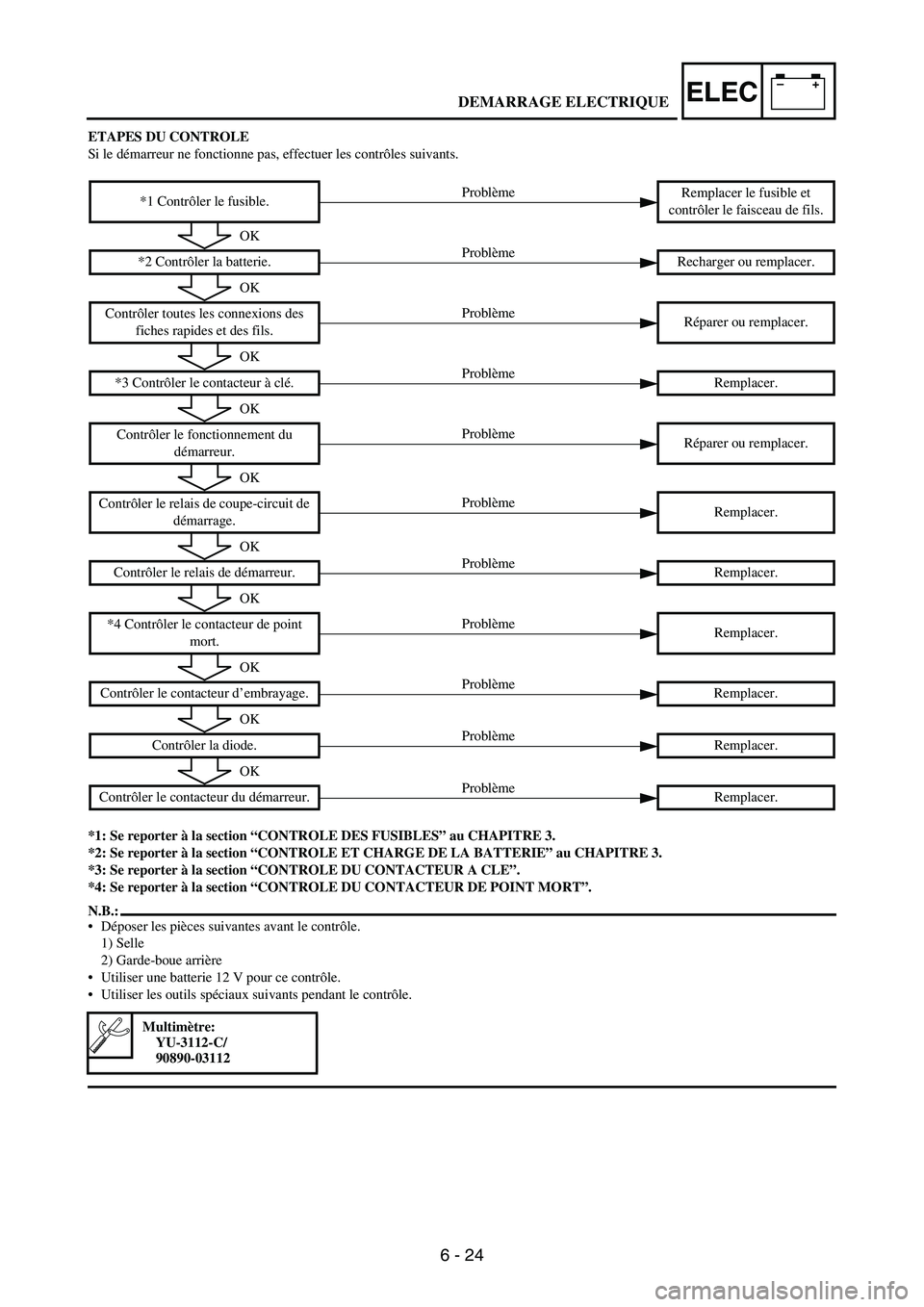
ETAPES DU CONTROLE
Si le démarreur ne fonctionne pas, effectuer les contrôles suivants.
*1: Se reporter à la section “CONTROLE DES FUSIBLES” au CHAPITRE 3.
*2: Se reporter à la section “CONTROLE ET CHARGE DE LA BATTERIE” au CHAPITRE 3.
*3: Se reporter à la section “CONTROLE DU CONTACTEUR A CLE”.
*4: Se reporter à la section “CONTROLE DU CONTACTEUR DE POINT MORT”.
N.B.:
Déposer les pièces suivantes avant le contrôle.
1) Selle
2) Garde-boue arrière
Utiliser une batterie 12 V pour ce contrôle.
Utiliser les outils spéciaux suivants pendant le contrôle.
*1 Contrôler le fusible.Remplacer le fusible et
contrôler le faisceau de fils.
*2 Contrôler la batterie. Recharger ou remplacer.
Contrôler toutes les connexions des
fiches rapides et des fils.Réparer ou remplacer.
*3 Contrôler le contacteur à clé. Remplacer.
Contrôler le fonctionnement du
démarreur.Réparer ou remplacer.
Contrôler le relais de coupe-circuit de
démarrage.Remplacer.
Contrôler le relais de démarreur. Remplacer.
*4 Contrôler le contacteur de point
mort.Remplacer.
Contrôler le contacteur d’embrayage. Remplacer.
Contrôler la diode.Remplacer.
Contrôler le contacteur du démarreur. Remplacer.
Multimètre:
YU-3112-C/
90890-03112
Problème
OK
Problème
OK
Problème
OK
Problème
OK
Problème
OK
Problème
OK
Problème
OK
Problème
OK
Problème
OK
Problème
OK
Problème
DEMARRAGE ELECTRIQUE
Page 788 of 900
6 - 25
–+ELEC
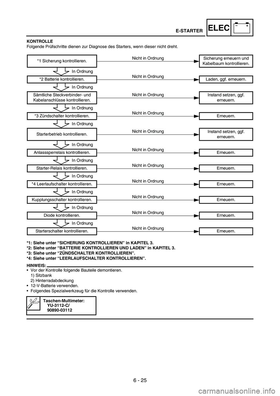
KONTROLLE
Folgende Prüfschritte dienen zur Diagnose des Starters, wenn dieser nicht dreht.
*1: Siehe unter “SICHERUNG KONTROLLIEREN” in KAPITEL 3.
*2: Siehe unter “BATTERIE KONTROLLIEREN UND LADEN” in KAPITEL 3.
*3: Siehe unter “ZÜNDSCHALTER KONTROLLIEREN”.
*4: Siehe unter “LEERLAUFSCHALTER KONTROLLIEREN”.
HINWEIS:
•Vor der Kontrolle folgende Bauteile demontieren.
1) Sitzbank
2) Hinterradabdeckung
•12-V-Batterie verwenden.
•Folgendes Spezialwerkzeug für die Kontrolle verwenden.
*1 Sicherung kontrollieren.Sicherung erneuern und
Kabelbaum kontrollieren.
*2 Batterie kontrollieren. Laden, ggf. erneuern.
Sämtliche Steckverbinder- und
Kabelanschlüsse kontrollieren.Instand setzen, ggf.
erneuern.
*3 Zündschalter kontrollieren. Erneuern.
Starterbetrieb kontrollieren.Instand setzen, ggf.
erneuern.
Anlasssperrelais kontrollieren. Erneuern.
Starter-Relais kontrollieren. Erneuern.
*4 Leerlaufschalter kontrollieren. Erneuern.
Kupplungsschalter kontrollieren. Erneuern.
Diode kontrollieren.Erneuern.
Starterschalter kontrollieren. Erneuern.
Taschen-Multimeter:
YU-3112-C/
90890-03112
Nicht in Ordnung
In Ordnung
Nicht in Ordnung
In Ordnung
Nicht in Ordnung
In Ordnung
Nicht in Ordnung
In Ordnung
Nicht in Ordnung
In Ordnung
Nicht in Ordnung
In Ordnung
Nicht in Ordnung
In Ordnung
Nicht in Ordnung
In Ordnung
Nicht in Ordnung
In Ordnung
Nicht in Ordnung
In Ordnung
Nicht in Ordnung
E-STARTER
Page 789 of 900
6 - 26
–+ELEC
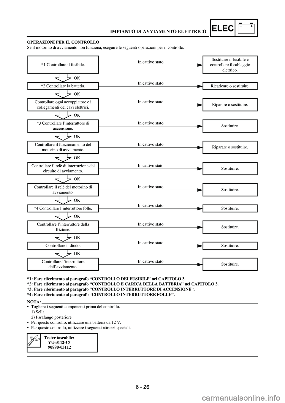
OPERAZIONI PER IL CONTROLLO
Se il motorino di avviamento non funziona, eseguire le seguenti operazioni per il controllo.
*1: Fare riferimento al paragrafo “CONTROLLO DEI FUSIBILI” nel CAPITOLO 3.
*2: Fare riferimento al paragrafo “CONTROLLO E CARICA DELLA BATTERIA” nel CAPITOLO 3.
*3: Fare riferimento al paragrafo “CONTROLLO INTERRUTTORE DI ACCENSIONE”.
*4: Fare riferimento al paragrafo “CONTROLLO INTERRUTTORE FOLLE”.
NOTA:
Togliere i seguenti componenti prima del controllo.
1) Sella
2) Parafango posteriore
Per questo controllo, utilizzare una batteria da 12 V.
Per questo controllo, utilizzare i seguenti attrezzi speciali.
*1 Controllare il fusibile.Sostituire il fusibile e
controllare il cablaggio
elettrico.
*2 Controllare la batteria. Ricaricare o sostituire.
Controllare ogni accoppiatore e i
collegamenti dei cavi elettrici.Riparare o sostituire.
*3 Controllare l’interruttore di
accensione.Sostituire.
Controllare il funzionamento del
motorino di avviamento. Riparare o sostituire.
Controllare il relè di interruzione del
circuito di avviamento.Sostituire.
Controllare il relè del motorino di
avviamento. Sostituire.
*4 Controllare l’interruttore folle. Sostituire.
Controllare l’interruttore della
frizione.Sostituire.
Controllare il diodo.Sostituire.
Controllare l’interruttore
dell’avviamento.Sostituire.
Tester tascabile:
YU-3112-C/
90890-03112
In cattivo stato
OK
In cattivo stato
OK
In cattivo stato
OK
In cattivo stato
OK
In cattivo stato
OK
In cattivo stato
OK
In cattivo stato
OK
In cattivo stato
OK
In cattivo stato
OK
In cattivo stato
OK
In cattivo stato
IMPIANTO DI AVVIAMENTO ELETTRICO
Page 790 of 900

6 - 27
–+ELEC
PROCEDIMIENTO DE REVISIÓN
Si el motor de arranque no funciona utilice el procedimiento de comprobación siguiente.
*1 marcado: Consulte el apartado “COMPROBACIÓN DE LOS FUSIBLES” del CAPÍTULO 3.
*2 marcado: Consulte el apartado “COMPROBACIÓN Y CARGA DE LA BATERÍA” del CAPÍTULO 3.
*3 marcado: Consulte el apartado “COMPROBACIÓN DEL INTERRUPTOR PRINCIPAL”.
*4 marcado: Consulte el apartado “COMPROBACIÓN DEL INTERRUPTOR DE LUZ DE PUNTO MUERTO”.
NOTA:
•Desmontar las piezas siguientes antes de proceder a la revisión.
1) Sillín
2) Guardabarros trasero
•Utilice una batería de 12 V en esta comprobación.
•Utilice las herramientas especiales siguientes en esta revisión.
*1 Comprobar fusible.Cambiar el fusible y
comprobar el mazo de
cables.
*2 Comprobar batería. Recargar o cambiar.
Comprobar las conexiones de
todos los acopladores y cables.Reparar o cambiar.
*3 Comprobar el interruptor
principal.Cambiar.
Comprobar el funcionamiento del
motor de arranque.Reparar o cambiar.
Comprobar el relé de corte del
circuito de arranque averiadoCambiar.
Comprobar el relé de arranque Cambiar.
*4 Comprobar el interruptor de luz
de punto muerto.Cambiar.
Comprobar el interruptor del
embrague.Cambiar.
Comprobar el diodo.Cambiar.
Comprobar el interruptor de
arranque.Cambiar.
Comprobador de
bolsillo:
YU-3112-C/
90890-03112
Incorrecto
Correcto
Incorrecto
Correcto
Incorrecto
Correcto
Incorrecto
Correcto
Incorrecto
Correcto
Incorrecto
Correcto
Incorrecto
Correcto
Incorrecto
Correcto
Incorrecto
Correcto
Incorrecto
Correcto
Incorrecto
SISTEMA DE ARRANQUE ELÉCTRICO