YAMAHA WR 250F 2007 Notices Demploi (in French)
Manufacturer: YAMAHA, Model Year: 2007, Model line: WR 250F, Model: YAMAHA WR 250F 2007Pages: 912, PDF Size: 23.95 MB
Page 101 of 912
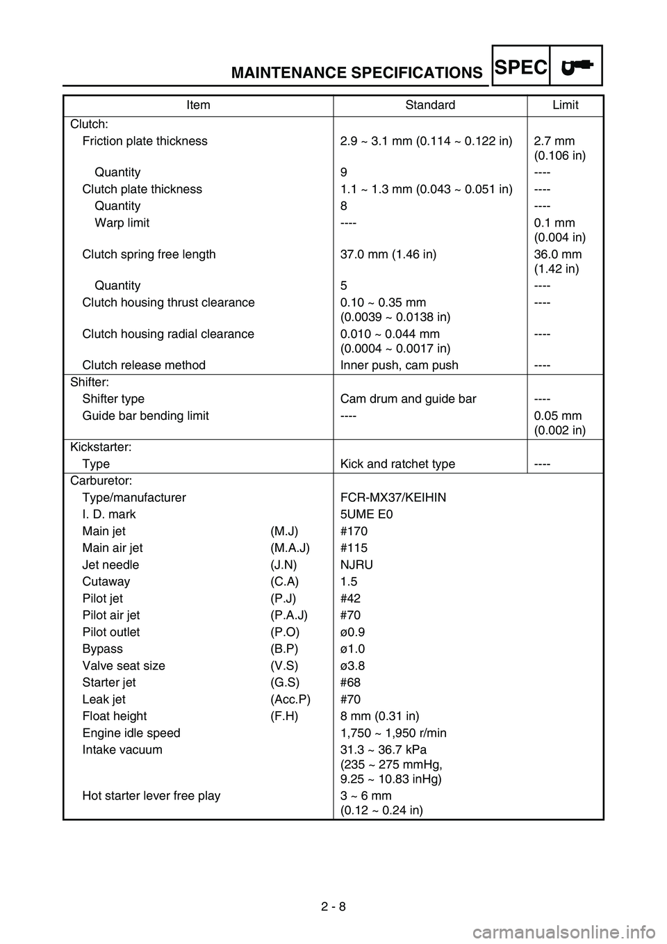
MAINTENANCE SPECIFICATIONS
2 - 8
SPEC
Clutch:
Friction plate thickness 2.9 ~ 3.1 mm (0.114 ~ 0.122 in) 2.7 mm
(0.106 in)
Quantity 9 ----
Clutch plate thickness 1.1 ~ 1.3 mm (0.043 ~ 0.051 in) ----
Quantity 8 ----
Warp limit ---- 0.1 mm
(0.004 in)
Clutch spring free length 37.0 mm (1.46 in) 36.0 mm
(1.42 in)
Quantity 5 ----
Clutch housing thrust clearance 0.10 ~ 0.35 mm
(0.0039 ~ 0.0138 in)----
Clutch housing radial clearance 0.010 ~ 0.044 mm
(0.0004 ~ 0.0017 in)----
Clutch release method Inner push, cam push ----
Shifter:
Shifter type Cam drum and guide bar ----
Guide bar bending limit ---- 0.05 mm
(0.002 in)
Kickstarter:
Type Kick and ratchet type ----
Carburetor:
Type/manufacturer FCR-MX37/KEIHIN
I. D. mark 5UME E0
Main jet (M.J) #170
Main air jet (M.A.J) #115
Jet needle (J.N) NJRU
Cutaway (C.A) 1.5
Pilot jet (P.J) #42
Pilot air jet (P.A.J) #70
Pilot outlet (P.O)ø0.9
Bypass (B.P)ø1.0
Valve seat size (V.S)ø3.8
Starter jet (G.S) #68
Leak jet (Acc.P) #70
Float height (F.H) 8 mm (0.31 in)
Engine idle speed 1,750 ~ 1,950 r/min
Intake vacuum 31.3 ~ 36.7 kPa
(235 ~ 275 mmHg,
9.25 ~ 10.83 inHg)
Hot starter lever free play 3 ~ 6 mm
(0.12 ~ 0.24 in) Item Standard Limit
Page 102 of 912
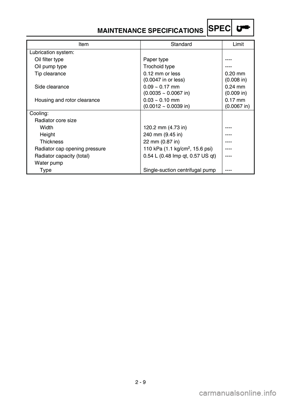
MAINTENANCE SPECIFICATIONS
2 - 9
SPEC
Lubrication system:
Oil filter type Paper type ----
Oil pump type Trochoid type ----
Tip clearance 0.12 mm or less
(0.0047 in or less)0.20 mm
(0.008 in)
Side clearance 0.09 ~ 0.17 mm
(0.0035 ~ 0.0067 in)0.24 mm
(0.009 in)
Housing and rotor clearance 0.03 ~ 0.10 mm
(0.0012 ~ 0.0039 in)0.17 mm
(0.0067 in)
Cooling:
Radiator core size
Width 120.2 mm (4.73 in) ----
Height 240 mm (9.45 in) ----
Thickness 22 mm (0.87 in) ----
Radiator cap opening pressure 110 kPa (1.1 kg/cm
2, 15.6 psi) ----
Radiator capacity (total) 0.54 L (0.48 Imp qt, 0.57 US qt) ----
Water pump
Type Single-suction centrifugal pump ----Item Standard Limit
Page 103 of 912
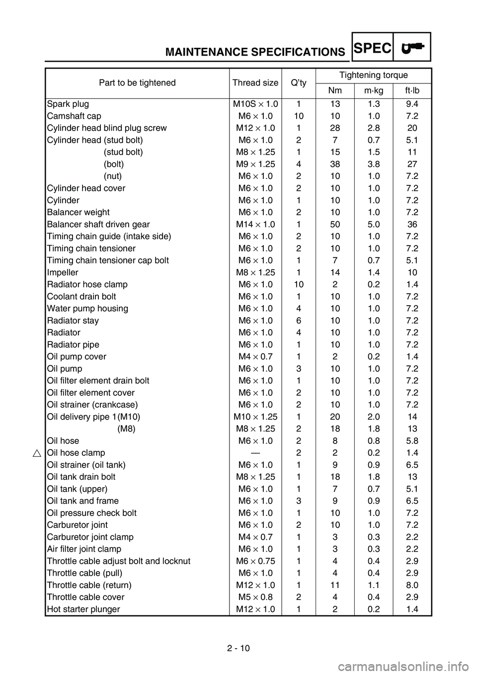
MAINTENANCE SPECIFICATIONS
2 - 10
SPEC
Part to be tightened Thread size Q’tyTightening torque
Nm m·kg ft·lb
Spark plug M10S × 1.0 1 13 1.3 9.4
Camshaft cap M6 × 1.0 10 10 1.0 7.2
Cylinder head blind plug screw M12 × 1.0 1 28 2.8 20
Cylinder head (stud bolt) M6 × 1.0 2 7 0.7 5.1
(stud bolt) M8 × 1.25 1 15 1.5 11
(bolt) M9 × 1.25 4 38 3.8 27
(nut) M6 × 1.0 2 10 1.0 7.2
Cylinder head cover M6 × 1.0 2 10 1.0 7.2
Cylinder M6 × 1.0 1 10 1.0 7.2
Balancer weight M6 × 1.0 2 10 1.0 7.2
Balancer shaft driven gear M14 × 1.0 1 50 5.0 36
Timing chain guide (intake side) M6 × 1.0 2 10 1.0 7.2
Timing chain tensioner M6 × 1.0 2 10 1.0 7.2
Timing chain tensioner cap bolt M6 × 1.0 1 7 0.7 5.1
Impeller M8 × 1.25 1 14 1.4 10
Radiator hose clamp M6 × 1.0 10 2 0.2 1.4
Coolant drain bolt M6 × 1.0 1 10 1.0 7.2
Water pump housing M6 × 1.0 4 10 1.0 7.2
Radiator stay M6 × 1.0 6 10 1.0 7.2
Radiator M6 × 1.0 4 10 1.0 7.2
Radiator pipe M6 × 1.0 1 10 1.0 7.2
Oil pump cover M4 × 0.7 1 2 0.2 1.4
Oil pump M6 × 1.0 3 10 1.0 7.2
Oil filter element drain bolt M6 × 1.0 1 10 1.0 7.2
Oil filter element cover M6 × 1.0 2 10 1.0 7.2
Oil strainer (crankcase) M6 × 1.0 2 10 1.0 7.2
Oil delivery pipe 1 (M10) M10 × 1.25 1 20 2.0 14
(M8) M8 × 1.25 2 18 1.8 13
Oil hose M6 × 1.0 2 8 0.8 5.8
Oil hose clamp—220.21.4
Oil strainer (oil tank) M6 × 1.0 1 9 0.9 6.5
Oil tank drain bolt M8 × 1.25 1 18 1.8 13
Oil tank (upper) M6 × 1.0 1 7 0.7 5.1
Oil tank and frame M6 × 1.0 3 9 0.9 6.5
Oil pressure check bolt M6 × 1.0 1 10 1.0 7.2
Carburetor joint M6 × 1.0 2 10 1.0 7.2
Carburetor joint clamp M4 × 0.7 1 3 0.3 2.2
Air filter joint clamp M6 × 1.0 1 3 0.3 2.2
Throttle cable adjust bolt and locknut M6 × 0.75 1 4 0.4 2.9
Throttle cable (pull) M6 × 1.0 1 4 0.4 2.9
Throttle cable (return) M12 × 1.0 1 11 1.1 8.0
Throttle cable cover M5 × 0.8 2 4 0.4 2.9
Hot starter plunger M12 × 1.0 1 2 0.2 1.4
Page 104 of 912
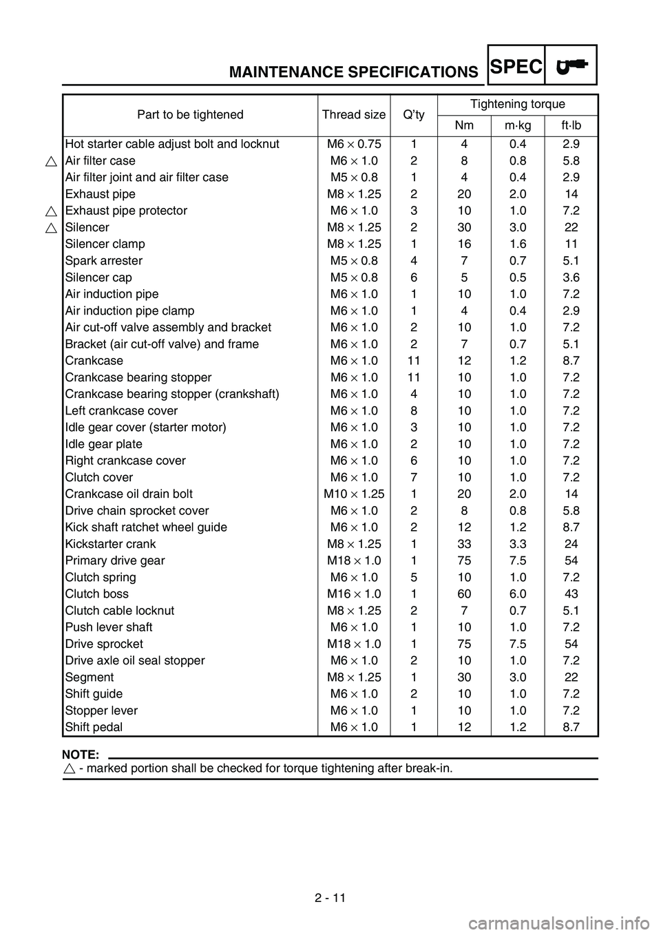
MAINTENANCE SPECIFICATIONS
2 - 11
SPEC
NOTE:
- marked portion shall be checked for torque tightening after break-in. Hot starter cable adjust bolt and locknut M6 × 0.75 1 4 0.4 2.9
Air filter case M6 × 1.0 2 8 0.8 5.8
Air filter joint and air filter case M5 × 0.8 1 4 0.4 2.9
Exhaust pipe M8 × 1.25 2 20 2.0 14
Exhaust pipe protector M6 × 1.0 3 10 1.0 7.2
Silencer M8 × 1.25 2 30 3.0 22
Silencer clamp M8 × 1.25 1 16 1.6 11
Spark arrester M5 × 0.8 4 7 0.7 5.1
Silencer cap M5 × 0.8 6 5 0.5 3.6
Air induction pipe M6 × 1.0 1 10 1.0 7.2
Air induction pipe clamp M6 × 1.0 1 4 0.4 2.9
Air cut-off valve assembly and bracket M6 × 1.0 2 10 1.0 7.2
Bracket (air cut-off valve) and frame M6 × 1.0 2 7 0.7 5.1
Crankcase M6 × 1.0 11 12 1.2 8.7
Crankcase bearing stopper M6 × 1.0 11 10 1.0 7.2
Crankcase bearing stopper (crankshaft) M6 × 1.0 4 10 1.0 7.2
Left crankcase cover M6 × 1.0 8 10 1.0 7.2
Idle gear cover (starter motor) M6 × 1.0 3 10 1.0 7.2
Idle gear plate M6 × 1.0 2 10 1.0 7.2
Right crankcase cover M6 × 1.0 6 10 1.0 7.2
Clutch cover M6 × 1.0 7 10 1.0 7.2
Crankcase oil drain bolt M10 × 1.25 1 20 2.0 14
Drive chain sprocket cover M6 × 1.0 2 8 0.8 5.8
Kick shaft ratchet wheel guide M6 × 1.0 2 12 1.2 8.7
Kickstarter crank M8 × 1.25 1 33 3.3 24
Primary drive gear M18 × 1.0 1 75 7.5 54
Clutch spring M6 × 1.0 5 10 1.0 7.2
Clutch boss M16 × 1.0 1 60 6.0 43
Clutch cable locknut M8 × 1.25 2 7 0.7 5.1
Push lever shaft M6 × 1.0 1 10 1.0 7.2
Drive sprocket M18 × 1.0 1 75 7.5 54
Drive axle oil seal stopper M6 × 1.0 2 10 1.0 7.2
Segment M8 × 1.25 1 30 3.0 22
Shift guide M6 × 1.0 2 10 1.0 7.2
Stopper lever M6 × 1.0 1 10 1.0 7.2
Shift pedal M6 × 1.0 1 12 1.2 8.7 Part to be tightened Thread size Q’tyTightening torque
Nm m·kg ft·lb
Page 105 of 912
MAINTENANCE SPECIFICATIONS
2 - 12
SPEC
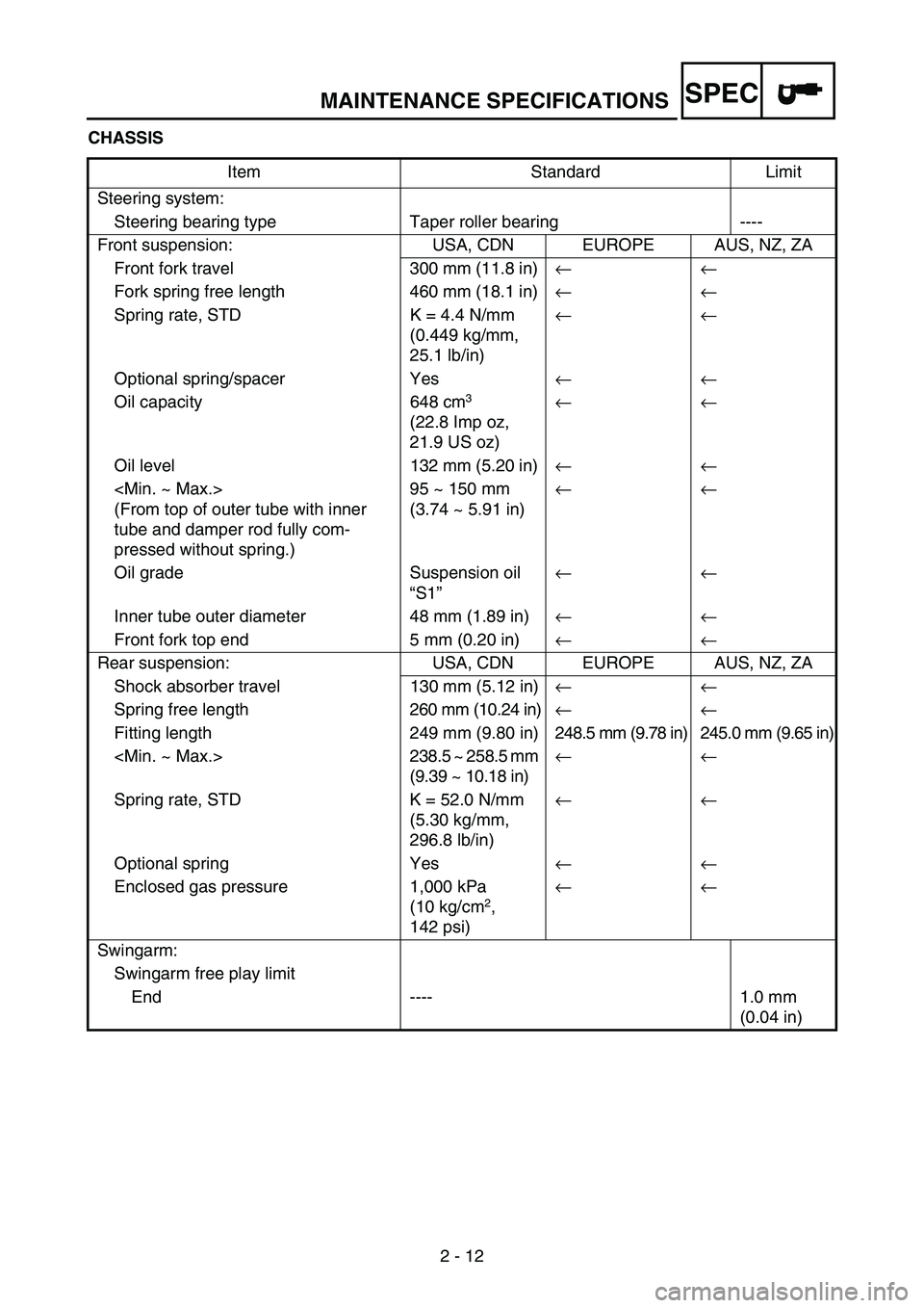
CHASSIS
Item Standard Limit
Steering system:
Steering bearing type Taper roller bearing ----
Front suspension: USA, CDN EUROPE AUS, NZ, ZA
Front fork travel 300 mm (11.8 in)←←
Fork spring free length 460 mm (18.1 in)←←
Spring rate, STD K = 4.4 N/mm
(0.449 kg/mm,
25.1 lb/in)←←
Optional spring/spacer Yes←←
Oil capacity 648 cm
3
(22.8 Imp oz,
21.9 US oz) ←←
Oil level 132 mm (5.20 in)←←
(From top of outer tube with inner
tube and damper rod fully com-
pressed without spring.)95 ~ 150 mm
(3.74 ~ 5.91 in)←←
Oil grade Suspension oil
“S1”←←
Inner tube outer diameter 48 mm (1.89 in)←←
Front fork top end 5 mm (0.20 in)←←
Rear suspension: USA, CDN EUROPE AUS, NZ, ZA
Shock absorber travel 130 mm (5.12 in)← ←
Spring free length260 mm (10.24 in)← ←
Fitting length 249 mm (9.80 in) 248.5 mm (9.78 in) 245.0 mm (9.65 in)
(9.39 ~ 10.18 in)← ←
Spring rate, STD K = 52.0 N/mm
(5.30 kg/mm,
296.8 lb/in)← ←
Optional spring Yes← ←
Enclosed gas pressure 1,000 kPa
(10 kg/cm
2,
142 psi)← ←
Swingarm:
Swingarm free play limit
End ---- 1.0 mm
(0.04 in)
Page 106 of 912
MAINTENANCE SPECIFICATIONS
2 - 13
SPEC
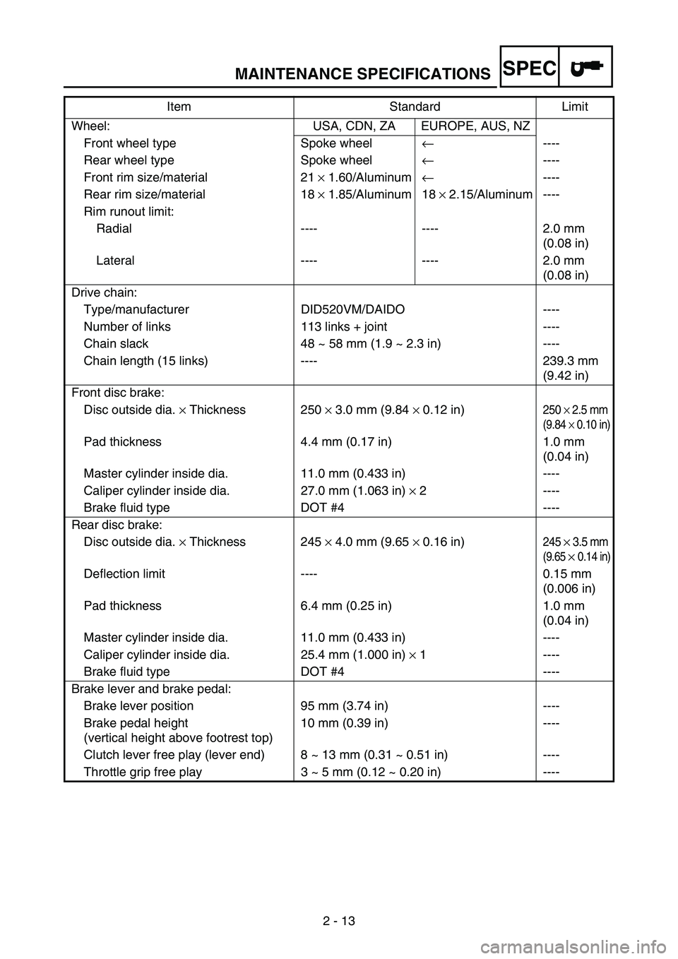
Wheel: USA, CDN, ZA EUROPE, AUS, NZ
Front wheel type Spoke wheel← ----
Rear wheel type Spoke wheel← ----
Front rim size/material 21 × 1.60/Aluminum← ----
Rear rim size/material 18 × 1.85/Aluminum 18 × 2.15/Aluminum ----
Rim runout limit:
Radial ---- ---- 2.0 mm
(0.08 in)
Lateral ---- ---- 2.0 mm
(0.08 in)
Drive chain:
Type/manufacturer DID520VM/DAIDO ----
Number of links 113 links + joint ----
Chain slack 48 ~ 58 mm (1.9 ~ 2.3 in) ----
Chain length (15 links) ---- 239.3 mm
(9.42 in)
Front disc brake:
Disc outside dia. × Thickness 250 × 3.0 mm (9.84 × 0.12 in)
250 × 2.5 mm
(9.84 × 0.10 in)
Pad thickness 4.4 mm (0.17 in) 1.0 mm
(0.04 in)
Master cylinder inside dia. 11.0 mm (0.433 in) ----
Caliper cylinder inside dia. 27.0 mm (1.063 in) × 2 ----
Brake fluid type DOT #4 ----
Rear disc brake:
Disc outside dia. × Thickness 245 × 4.0 mm (9.65 × 0.16 in)
245 × 3.5 mm
(9.65 × 0.14 in)
Deflection limit ---- 0.15 mm
(0.006 in)
Pad thickness 6.4 mm (0.25 in) 1.0 mm
(0.04 in)
Master cylinder inside dia. 11.0 mm (0.433 in) ----
Caliper cylinder inside dia. 25.4 mm (1.000 in) × 1 ----
Brake fluid type DOT #4 ----
Brake lever and brake pedal:
Brake lever position 95 mm (3.74 in) ----
Brake pedal height
(vertical height above footrest top)10 mm (0.39 in) ----
Clutch lever free play (lever end) 8 ~ 13 mm (0.31 ~ 0.51 in) ----
Throttle grip free play 3 ~ 5 mm (0.12 ~ 0.20 in) ----Item Standard Limit
Page 107 of 912
MAINTENANCE SPECIFICATIONS
2 - 14
SPEC
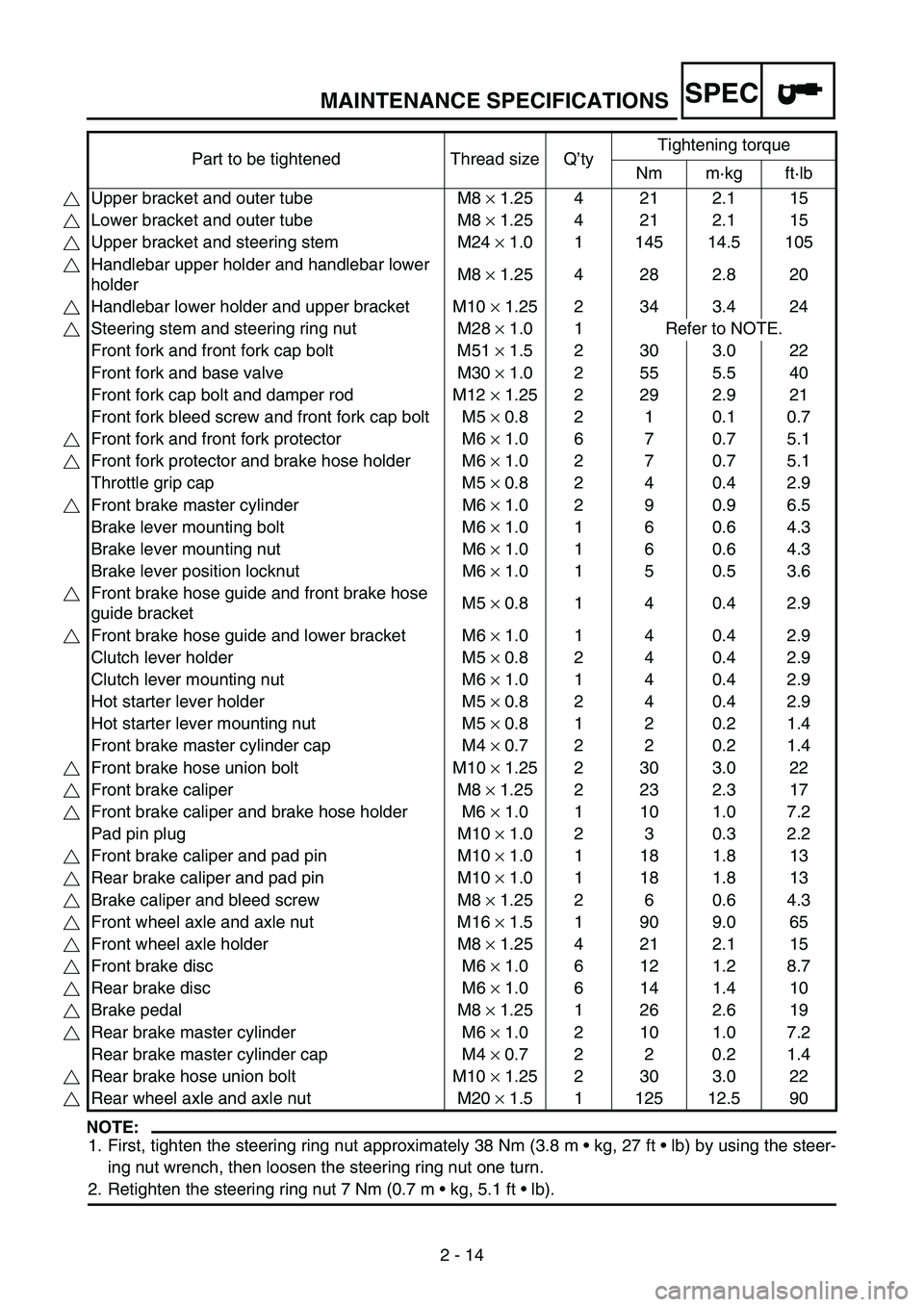
NOTE:
1. First, tighten the steering ring nut approximately 38 Nm (3.8 m kg, 27 ft lb) by using the steer-
ing nut wrench, then loosen the steering ring nut one turn.
2. Retighten the steering ring nut 7 Nm (0.7 m kg, 5.1 ft lb). Part to be tightened Thread size Q’tyTightening torque
Nm m·kg ft·lb
Upper bracket and outer tube M8 × 1.25 4 21 2.1 15
Lower bracket and outer tube M8 × 1.25 4 21 2.1 15
Upper bracket and steering stem M24 × 1.0 1 145 14.5 105
Handlebar upper holder and handlebar lower
holderM8 × 1.25 4 28 2.8 20
Handlebar lower holder and upper bracket M10 × 1.25 2 34 3.4 24
Steering stem and steering ring nut M28 × 1.0 1 Refer to NOTE.
Front fork and front fork cap bolt M51 × 1.5 2 30 3.0 22
Front fork and base valve M30 × 1.0 2 55 5.5 40
Front fork cap bolt and damper rod M12 × 1.25 2 29 2.9 21
Front fork bleed screw and front fork cap bolt M5 × 0.8 2 1 0.1 0.7
Front fork and front fork protector M6 × 1.0 6 7 0.7 5.1
Front fork protector and brake hose holder M6 × 1.0 2 7 0.7 5.1
Throttle grip cap M5 × 0.8 2 4 0.4 2.9
Front brake master cylinder M6 × 1.0 2 9 0.9 6.5
Brake lever mounting bolt M6 × 1.0 1 6 0.6 4.3
Brake lever mounting nut M6 × 1.0 1 6 0.6 4.3
Brake lever position locknut M6 × 1.0 1 5 0.5 3.6
Front brake hose guide and front brake hose
guide bracketM5 × 0.8 1 4 0.4 2.9
Front brake hose guide and lower bracket M6 × 1.0 1 4 0.4 2.9
Clutch lever holder M5 × 0.8 2 4 0.4 2.9
Clutch lever mounting nut M6 × 1.0 1 4 0.4 2.9
Hot starter lever holder M5 × 0.8 2 4 0.4 2.9
Hot starter lever mounting nut M5 × 0.8 1 2 0.2 1.4
Front brake master cylinder cap M4 × 0.7 2 2 0.2 1.4
Front brake hose union bolt M10 × 1.25 2 30 3.0 22
Front brake caliper M8 × 1.25 2 23 2.3 17
Front brake caliper and brake hose holder M6 × 1.0 1 10 1.0 7.2
Pad pin plug M10 × 1.0 2 3 0.3 2.2
Front brake caliper and pad pin M10 × 1.0 1 18 1.8 13
Rear brake caliper and pad pin M10 × 1.0 1 18 1.8 13
Brake caliper and bleed screw M8 × 1.25 2 6 0.6 4.3
Front wheel axle and axle nut M16 × 1.5 1 90 9.0 65
Front wheel axle holder M8 × 1.25 4 21 2.1 15
Front brake disc M6 × 1.0 6 12 1.2 8.7
Rear brake disc M6 × 1.0 6 14 1.4 10
Brake pedal M8 × 1.25 1 26 2.6 19
Rear brake master cylinder M6 × 1.0 2 10 1.0 7.2
Rear brake master cylinder cap M4 × 0.7 2 2 0.2 1.4
Rear brake hose union bolt M10 × 1.25 2 30 3.0 22
Rear wheel axle and axle nut M20 × 1.5 1 125 12.5 90
Page 108 of 912

MAINTENANCE SPECIFICATIONS
2 - 15
SPEC
Part to be tightened Thread size Q’tyTightening torque
Nm m·kg ft·lb
Nipple (spoke)—72 3 0.3 2.2
Rear wheel sprocket M8 × 1.25 6 50 5.0 36
Rear brake disc cover M6 × 1.0 2 10 1.0 7.2
Rear brake caliper protector M6 × 1.0 2 7 0.7 5.1
Drive chain puller adjust bolt and locknut M8 × 1.25 2 19 1.9 13
Engine mounting:
Engine and engine bracket (front) M10 × 1.25 1 53 5.3 38
Engine and frame (lower) M10 × 1.25 1 53 5.3 38
Upper engine bracket and frame M8 × 1.25 4 34 3.4 24
Lower engine bracket and frame M8 × 1.25 4 34 3.4 24
Engine and engine bracket (upper) M10 × 1.25 1 55 5.5 40
Engine guard M6 × 1.0 3 7 0.7 5.1
Regulator M6 × 1.0 2 7 0.7 5.1
Pivot shaft and nut M16 × 1.5 1 85 8.5 61
Relay arm and swingarm M14 × 1.5 1 70 7.0 50
Relay arm and connecting rod M14 × 1.5 1 80 8.0 58
Connecting rod and frame M14 × 1.5 1 80 8.0 58
Rear shock absorber and frame M10 × 1.25 1 56 5.6 40
Rear shock absorber and relay arm M10 × 1.25 1 53 5.3 38
Rear frame (upper) M8 × 1.25 1 38 3.8 27
Rear frame (lower) M8 × 1.25 2 32 3.2 23
Swingarm and brake hose holder M5 × 0.8 4 2 0.2 1.4
Swingarm and patch M4 × 0.7 4 2 0.2 1.4
Upper drive chain tensioner M8 × 1.25 1 16 1.6 11
Lower drive chain tensioner M8 × 1.25 1 16 1.6 11
Drive chain support M6 × 1.0 3 7 0.7 5.1
Seal guard and swingarm M5 × 0.8 4 6 0.6 4.3
Fuel tank M6 × 1.0 2 9 0.9 6.5
Fuel cock M6 × 1.0 2 4 0.4 2.9
Seat set bracket and fuel tank M6 × 1.0 1 7 0.7 5.1
Fuel tank bracket and fuel tank M6 × 1.0 4 7 0.7 5.1
Air scoop and fuel tank M6 × 1.0 6 7 0.7 5.1
Air scoop and radiator guard (lower) M6 × 1.0 2 6 0.6 4.3
Front fender M6 × 1.0 4 7 0.7 5.1
Rear fender (front) M6 × 1.0 2 7 0.7 5.1
Rear fender (rear) M6 × 1.0 2 11 1.1 8.0
Side cover M6 × 1.0 2 7 0.7 5.1
Seat M8 × 1.25 2 23 2.3 17
Multi-function display bracket and upper
bracketM6 × 1.0 2 7 0.7 5.1
Multi-function display M5 × 0.8 2 4 0.4 2.9
Plate 1 and front fork protector M5 × 0.8 2 4 0.4 2.9
Plate 2 and front fork protector—2 0.5 0.05 0.36
Page 109 of 912

MAINTENANCE SPECIFICATIONS
2 - 16
SPEC
NOTE:
- marked portion shall be checked for torque tightening after break-in. Speed sensor lead holder and lower bracket M6 × 1.0 1 13 1.3 9.4
Headlight body and headlight unit—210.10.7
Headlight (left and right) M6 × 1.0 2 7 0.7 5.1
Taillight—310.10.7
Taillight lead clamp and rear fender—3 0.5 0.05 0.36
Catch tank (upper) M6 × 1.0 1 16 1.6 11
Catch tank (lower) M6 × 1.0 1 7 0.7 5.1
Footrest bracket and frame M10 × 1.25 4 55 5.5 40
Sidestand M10 × 1.25 1 25 2.5 18 Part to be tightened Thread size Q’tyTightening torque
Nm m·kg ft·lb
Page 110 of 912
MAINTENANCE SPECIFICATIONS
2 - 17
SPEC
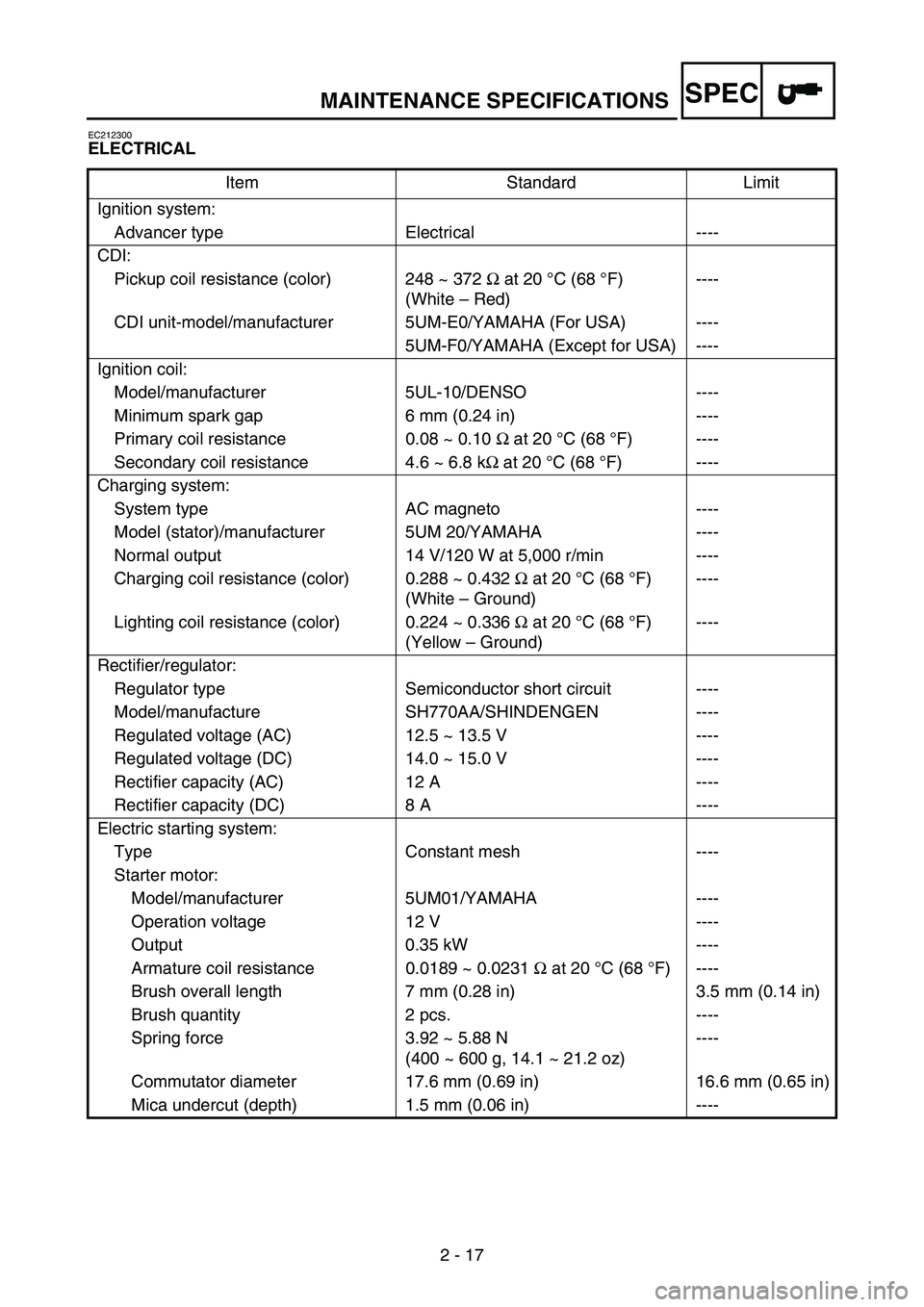
EC212300
ELECTRICAL
Item Standard Limit
Ignition system:
Advancer type Electrical ----
CDI:
Pickup coil resistance (color) 248 ~ 372 Ω at 20°C (68 °F)
(White – Red)----
CDI unit-model/manufacturer 5UM-E0/YAMAHA (For USA) ----
5UM-F0/YAMAHA (Except for USA) ----
Ignition coil:
Model/manufacturer 5UL-10/DENSO ----
Minimum spark gap 6 mm (0.24 in) ----
Primary coil resistance 0.08 ~ 0.10 Ω at 20 °C (68 °F) ----
Secondary coil resistance 4.6 ~ 6.8 kΩ at 20 °C (68 °F) ----
Charging system:
System type AC magneto ----
Model (stator)/manufacturer 5UM 20/YAMAHA ----
Normal output 14 V/120 W at 5,000 r/min ----
Charging coil resistance (color) 0.288 ~ 0.432 Ω at 20 °C (68 °F)
(White – Ground)----
Lighting coil resistance (color) 0.224 ~ 0.336 Ω at 20 °C (68 °F)
(Yellow – Ground)----
Rectifier/regulator:
Regulator type Semiconductor short circuit ----
Model/manufacture SH770AA/SHINDENGEN ----
Regulated voltage (AC) 12.5 ~ 13.5 V ----
Regulated voltage (DC) 14.0 ~ 15.0 V ----
Rectifier capacity (AC) 12 A ----
Rectifier capacity (DC) 8 A ----
Electric starting system:
Type Constant mesh ----
Starter motor:
Model/manufacturer 5UM01/YAMAHA ----
Operation voltage 12 V ----
Output 0.35 kW ----
Armature coil resistance 0.0189 ~ 0.0231 Ω at 20 °C (68 °F) ----
Brush overall length 7 mm (0.28 in) 3.5 mm (0.14 in)
Brush quantity 2 pcs. ----
Spring force 3.92 ~ 5.88 N
(400 ~ 600 g, 14.1 ~ 21.2 oz)----
Commutator diameter 17.6 mm (0.69 in) 16.6 mm (0.65 in)
Mica undercut (depth) 1.5 mm (0.06 in) ----