YAMAHA WR 250F 2014 Owners Manual
Manufacturer: YAMAHA, Model Year: 2014, Model line: WR 250F, Model: YAMAHA WR 250F 2014Pages: 230, PDF Size: 13.01 MB
Page 141 of 230
5-40
BALANCER
REMOVING THE BALANCER
1. Straighten the lock washer tab.
2. Loosen:
• Nut (primary drive gear) "1"
• Nut (balancer shaft driven gear)
"2"
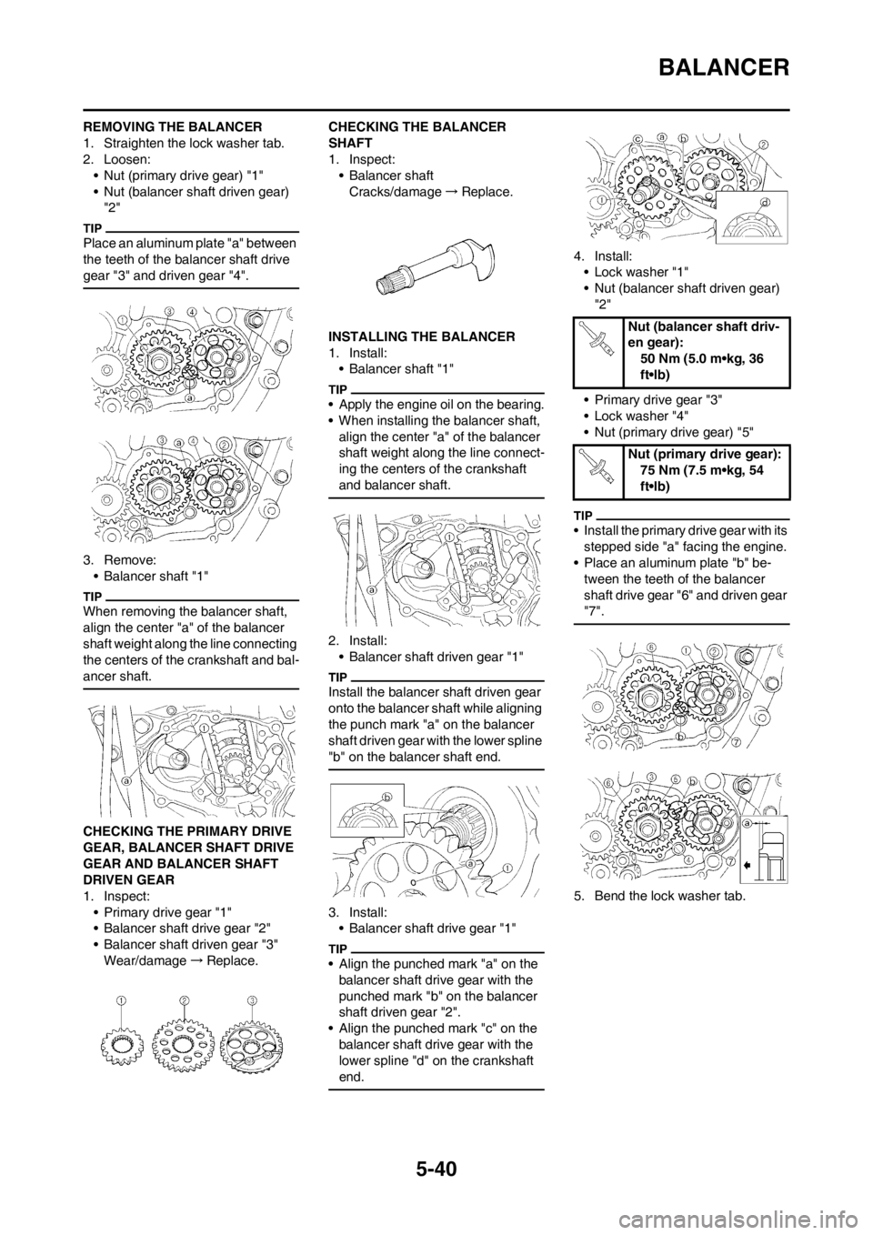
Place an aluminum plate "a" between
the teeth of the balancer shaft drive
gear "3" and driven gear "4".
3. Remove:
• Balancer shaft "1"
When removing the balancer shaft,
align the center "a" of the balancer
shaft weight along the line connecting
the centers of the crankshaft and bal-
ancer shaft.
CHECKING THE PRIMARY DRIVE
GEAR, BALANCER SHAFT DRIVE
GEAR AND BALANCER SHAFT
DRIVEN GEAR
1. Inspect:
• Primary drive gear "1"
• Balancer shaft drive gear "2"
• Balancer shaft driven gear "3"
Wear/damage→Replace.CHECKING THE BALANCER
SHAFT
1. Inspect:
• Balancer shaft
Cracks/damage→Replace.
INSTALLING THE BALANCER
1. Install:
• Balancer shaft "1"
• Apply the engine oil on the bearing.
• When installing the balancer shaft,
align the center "a" of the balancer
shaft weight along the line connect-
ing the centers of the crankshaft
and balancer shaft.
2. Install:
• Balancer shaft driven gear "1"
Install the balancer shaft driven gear
onto the balancer shaft while aligning
the punch mark "a" on the balancer
shaft driven gear with the lower spline
"b" on the balancer shaft end.
3. Install:
• Balancer shaft drive gear "1"
• Align the punched mark "a" on the
balancer shaft drive gear with the
punched mark "b" on the balancer
shaft driven gear "2".
• Align the punched mark "c" on the
balancer shaft drive gear with the
lower spline "d" on the crankshaft
end.
4. Install:
• Lock washer "1"
• Nut (balancer shaft driven gear)
"2"
• Primary drive gear "3"
• Lock washer "4"
• Nut (primary drive gear) "5"
• Install the primary drive gear with its
stepped side "a" facing the engine.
• Place an aluminum plate "b" be-
tween the teeth of the balancer
shaft drive gear "6" and driven gear
"7".
5. Bend the lock washer tab.
Nut (balancer shaft driv-
en gear):
50 Nm (5.0 m•kg, 36
ft•lb)
Nut (primary drive gear):
75 Nm (7.5 m•kg, 54
ft•lb)
Page 142 of 230
5-41
OIL PUMP
OIL PUMP
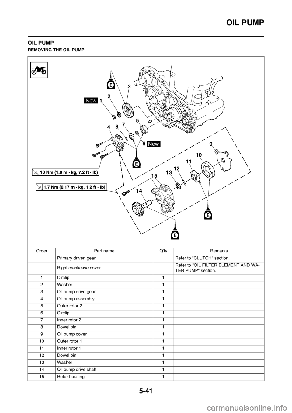
REMOVING THE OIL PUMP
Order Part name Q'ty Remarks
Primary driven gear Refer to "CLUTCH" section.
Right crankcase coverRefer to "OIL FILTER ELEMENT AND WA-
TER PUMP" section.
1 Circlip 1
2 Washer 1
3 Oil pump drive gear 1
4 Oil pump assembly 1
5 Outer rotor 2 1
6 Circlip 1
7 Inner rotor 2 1
8 Dowel pin 1
9 Oil pump cover 1
10 Outer rotor 1 1
11 Inner rotor 1 1
12 Dowel pin 1
13 Washer 1
14 Oil pump drive shaft 1
15 Rotor housing 1
Page 143 of 230
5-42
OIL PUMP
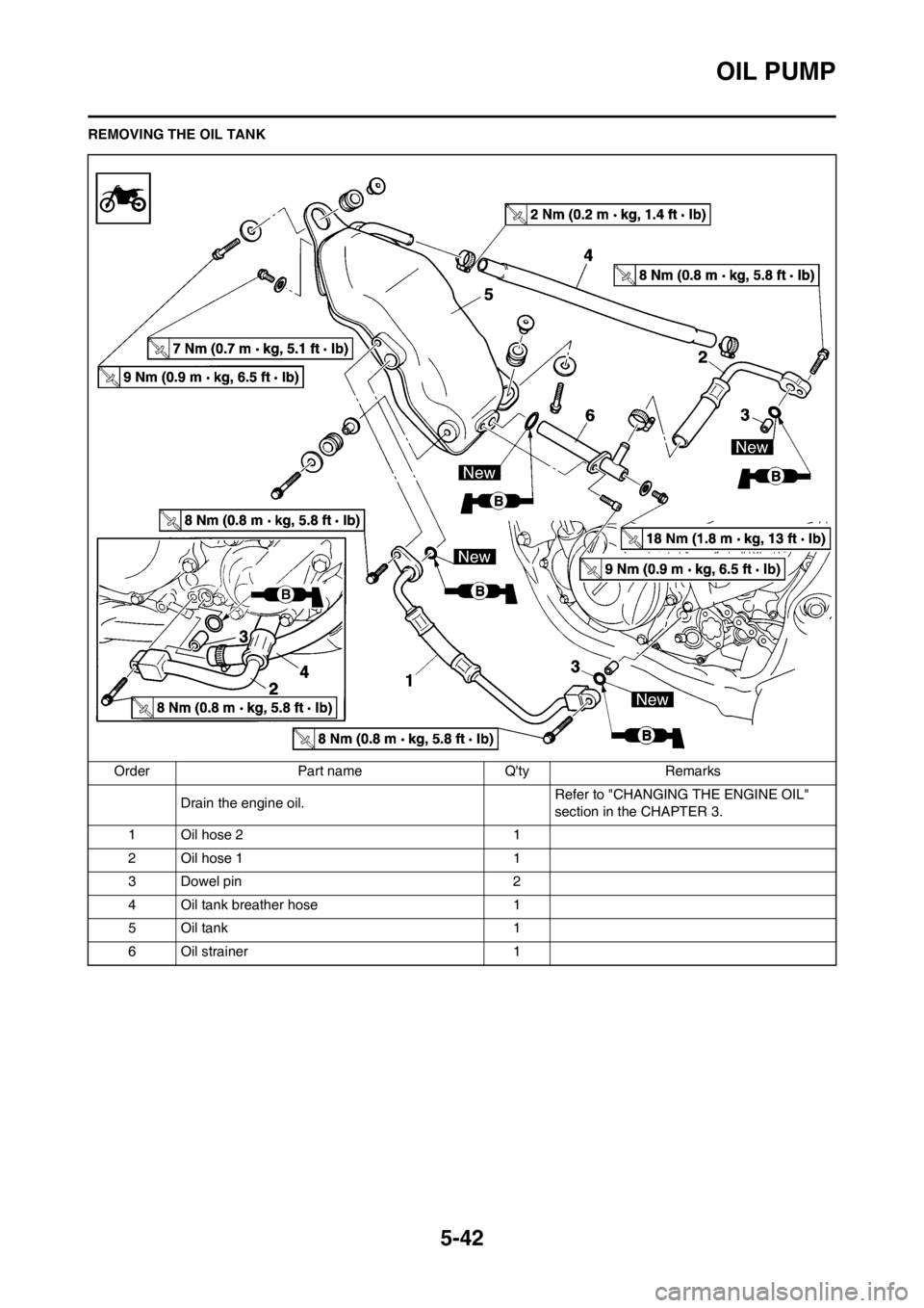
REMOVING THE OIL TANK
Order Part name Q'ty Remarks
Drain the engine oil.Refer to "CHANGING THE ENGINE OIL"
section in the CHAPTER 3.
1 Oil hose 2 1
2 Oil hose 1 1
3 Dowel pin 2
4 Oil tank breather hose 1
5 Oil tank 1
6 Oil strainer 1
Page 144 of 230
5-43
OIL PUMP
CHECKING THE OIL PUMP
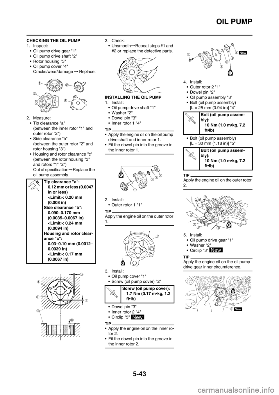
1. Inspect:
• Oil pump drive gear "1"
• Oil pump drive shaft "2"
• Rotor housing "3"
• Oil pump cover "4"
Cracks/wear/damage→Replace.
2. Measure:
• Tip clearance "a"
(between the inner rotor "1" and
outer rotor "2")
• Side clearance "b"
(between the outer rotor "2" and
rotor housing "3")
• Housing and rotor clearance "c"
(between the rotor housing "3"
and rotors "1" "2")
Out of specification→Replace the
oil pump assembly.3. Check:
• Unsmooth→Repeat steps #1 and
#2 or replace the defective parts.
INSTALLING THE OIL PUMP
1. Install:
• Oil pump drive shaft "1"
• Washer "2"
• Dowel pin "3"
• Inner rotor 1 "4"
• Apply the engine oil on the oil pump
drive shaft and inner rotor 1.
• Fit the dowel pin into the groove in
the inner rotor 1.
2. Install:
• Outer rotor 1 "1"
Apply the engine oil on the outer rotor
1.
3. Install:
• Oil pump cover "1"
• Screw (oil pump cover) "2"
• Dowel pin "3"
• Inner rotor 2 "4"
• Circlip "5"
• Apply the engine oil on the inner ro-
tor 2.
• Fit the dowel pin into the groove in
the inner rotor 2.
4. Install:
• Outer rotor 2 "1"
• Dowel pin "2"
• Oil pump assembly "3"
• Bolt (oil pump assembly)
[L = 25 mm (0.94 in)] "4"
• Bolt (oil pump assembly)
[L = 30 mm (1.18 in)] "5"
Apply the engine oil on the outer rotor
2.
5. Install:
• Oil pump drive gear "1"
• Washer "2"
• Circlip "3"
Apply the engine oil on the oil pump
drive gear inner circumference.
Tip clearance "a":
0.12 mm or less (0.0047
in or less)
(0.008 in)
Side clearance "b":
0.090–0.170 mm
(0.0035–0.0067 in)
(0.0094 in)
Housing and rotor clear-
ance "c":
0.03–0.10 mm (0.0012–
0.0039 in)
(0.0067 in)
Screw (oil pump cover):
1.7 Nm (0.17 m•kg, 1.2
ft•lb)
Bolt (oil pump assem-
bly):
10 Nm (1.0 m•kg, 7.2
ft•lb)
Bolt (oil pump assem-
bly):
10 Nm (1.0 m•kg, 7.2
ft•lb)
Page 145 of 230
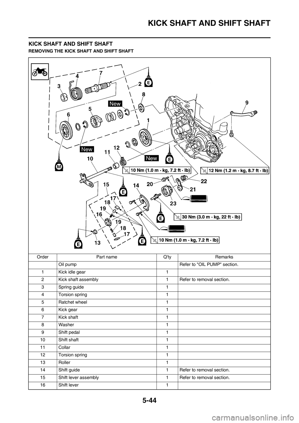
5-44
KICK SHAFT AND SHIFT SHAFT
KICK SHAFT AND SHIFT SHAFT
REMOVING THE KICK SHAFT AND SHIFT SHAFT
Order Part name Q'ty Remarks
Oil pump Refer to "OIL PUMP" section.
1 Kick idle gear 1
2 Kick shaft assembly 1 Refer to removal section.
3 Spring guide 1
4 Torsion spring 1
5 Ratchet wheel 1
6 Kick gear 1
7 Kick shaft 1
8 Washer 1
9 Shift pedal 1
10 Shift shaft 1
11 Collar 1
12 Torsion spring 1
13 Roller 1
14 Shift guide 1 Refer to removal section.
15 Shift lever assembly 1 Refer to removal section.
16 Shift lever 1
Page 146 of 230
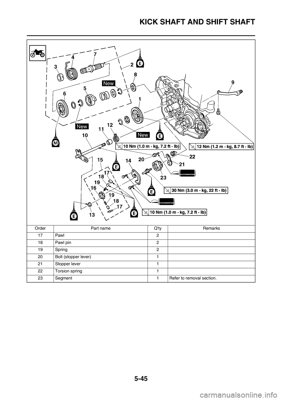
5-45
KICK SHAFT AND SHIFT SHAFT
17 Pawl 2
18 Pawl pin 2
19 Spring 2
20 Bolt (stopper lever) 1
21 Stopper lever 1
22 Torsion spring 1
23 Segment 1 Refer to removal section. Order Part name Q'ty Remarks
Page 147 of 230
5-46
KICK SHAFT AND SHIFT SHAFT
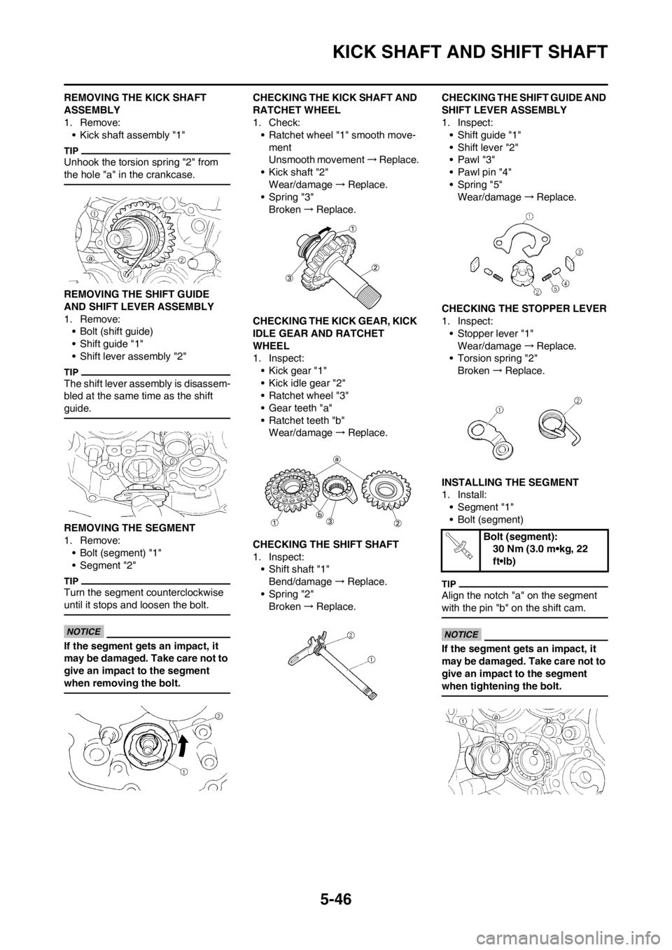
REMOVING THE KICK SHAFT
ASSEMBLY
1. Remove:
• Kick shaft assembly "1"
Unhook the torsion spring "2" from
the hole "a" in the crankcase.
REMOVING THE SHIFT GUIDE
AND SHIFT LEVER ASSEMBLY
1. Remove:
• Bolt (shift guide)
• Shift guide "1"
• Shift lever assembly "2"
The shift lever assembly is disassem-
bled at the same time as the shift
guide.
REMOVING THE SEGMENT
1. Remove:
• Bolt (segment) "1"
• Segment "2"
Turn the segment counterclockwise
until it stops and loosen the bolt.
If the segment gets an impact, it
may be damaged. Take care not to
give an impact to the segment
when removing the bolt.
CHECKING THE KICK SHAFT AND
RATCHET WHEEL
1. Check:
• Ratchet wheel "1" smooth move-
ment
Unsmooth movement→Replace.
• Kick shaft "2"
Wear/damage→Replace.
• Spring "3"
Broken→Replace.
CHECKING THE KICK GEAR, KICK
IDLE GEAR AND RATCHET
WHEEL
1. Inspect:
• Kick gear "1"
• Kick idle gear "2"
• Ratchet wheel "3"
• Gear teeth "a"
• Ratchet teeth "b"
Wear/damage→Replace.
CHECKING THE SHIFT SHAFT
1. Inspect:
• Shift shaft "1"
Bend/damage→Replace.
• Spring "2"
Broken→Replace.CHECKING THE SHIFT GUIDE AND
SHIFT LEVER ASSEMBLY
1. Inspect:
• Shift guide "1"
• Shift lever "2"
•Pawl "3"
• Pawl pin "4"
• Spring "5"
Wear/damage→Replace.
CHECKING THE STOPPER LEVER
1. Inspect:
• Stopper lever "1"
Wear/damage→Replace.
• Torsion spring "2"
Broken→Replace.
INSTALLING THE SEGMENT
1. Install:
• Segment "1"
• Bolt (segment)
Align the notch "a" on the segment
with the pin "b" on the shift cam.
If the segment gets an impact, it
may be damaged. Take care not to
give an impact to the segment
when tightening the bolt.
Bolt (segment):
30 Nm (3.0 m•kg, 22
ft•lb)
Page 148 of 230
5-47
KICK SHAFT AND SHIFT SHAFT
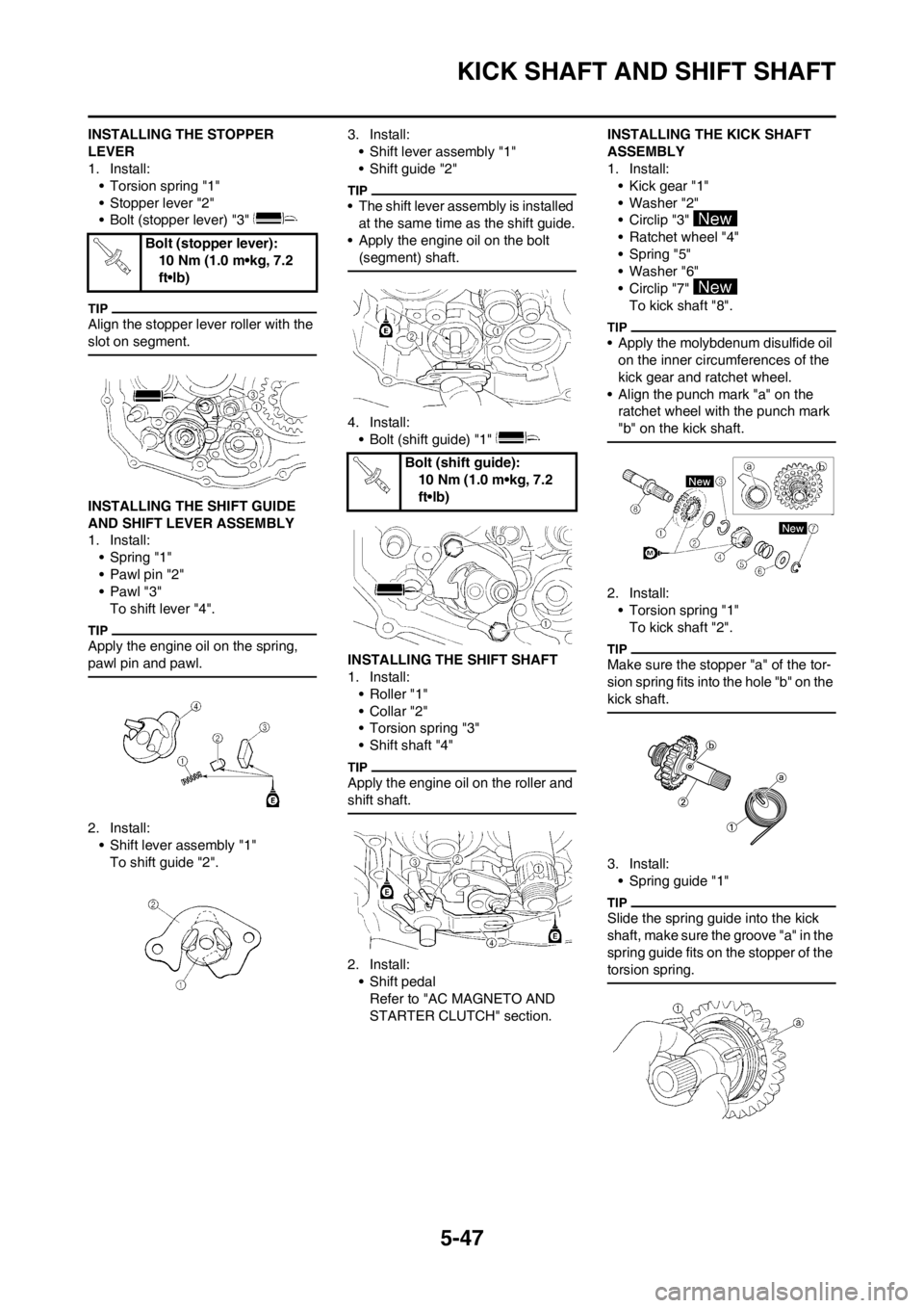
INSTALLING THE STOPPER
LEVER
1. Install:
• Torsion spring "1"
• Stopper lever "2"
• Bolt (stopper lever) "3"
Align the stopper lever roller with the
slot on segment.
INSTALLING THE SHIFT GUIDE
AND SHIFT LEVER ASSEMBLY
1. Install:
• Spring "1"
• Pawl pin "2"
•Pawl "3"
To shift lever "4".
Apply the engine oil on the spring,
pawl pin and pawl.
2. Install:
• Shift lever assembly "1"
To shift guide "2".3. Install:
• Shift lever assembly "1"
• Shift guide "2"
• The shift lever assembly is installed
at the same time as the shift guide.
• Apply the engine oil on the bolt
(segment) shaft.
4. Install:
• Bolt (shift guide) "1"
INSTALLING THE SHIFT SHAFT
1. Install:
• Roller "1"
• Collar "2"
• Torsion spring "3"
• Shift shaft "4"
Apply the engine oil on the roller and
shift shaft.
2. Install:
• Shift pedal
Refer to "AC MAGNETO AND
STARTER CLUTCH" section.INSTALLING THE KICK SHAFT
ASSEMBLY
1. Install:
• Kick gear "1"
• Washer "2"
• Circlip "3"
• Ratchet wheel "4"
• Spring "5"
• Washer "6"
• Circlip "7"
To kick shaft "8".
• Apply the molybdenum disulfide oil
on the inner circumferences of the
kick gear and ratchet wheel.
• Align the punch mark "a" on the
ratchet wheel with the punch mark
"b" on the kick shaft.
2. Install:
• Torsion spring "1"
To kick shaft "2".
Make sure the stopper "a" of the tor-
sion spring fits into the hole "b" on the
kick shaft.
3. Install:
• Spring guide "1"
Slide the spring guide into the kick
shaft, make sure the groove "a" in the
spring guide fits on the stopper of the
torsion spring.
Bolt (stopper lever):
10 Nm (1.0 m•kg, 7.2
ft•lb)
Bolt (shift guide):
10 Nm (1.0 m•kg, 7.2
ft•lb)
Page 149 of 230
5-48
KICK SHAFT AND SHIFT SHAFT
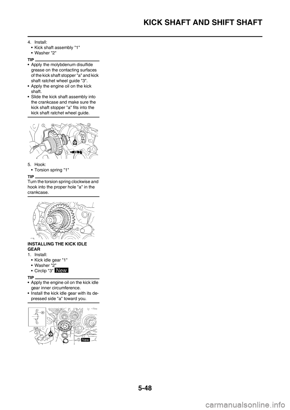
4. Install:
• Kick shaft assembly "1"
• Washer "2"
• Apply the molybdenum disulfide
grease on the contacting surfaces
of the kick shaft stopper "a" and kick
shaft ratchet wheel guide "3".
• Apply the engine oil on the kick
shaft.
• Slide the kick shaft assembly into
the crankcase and make sure the
kick shaft stopper "a" fits into the
kick shaft ratchet wheel guide.
5. Hook:
• Torsion spring "1"
Turn the torsion spring clockwise and
hook into the proper hole "a" in the
crankcase.
INSTALLING THE KICK IDLE
GEAR
1. Install:
• Kick idle gear "1"
• Washer "2"
• Circlip "3"
• Apply the engine oil on the kick idle
gear inner circumference.
• Install the kick idle gear with its de-
pressed side "a" toward you.
Page 150 of 230
5-49
AC MAGNETO AND STARTER CLUTCH
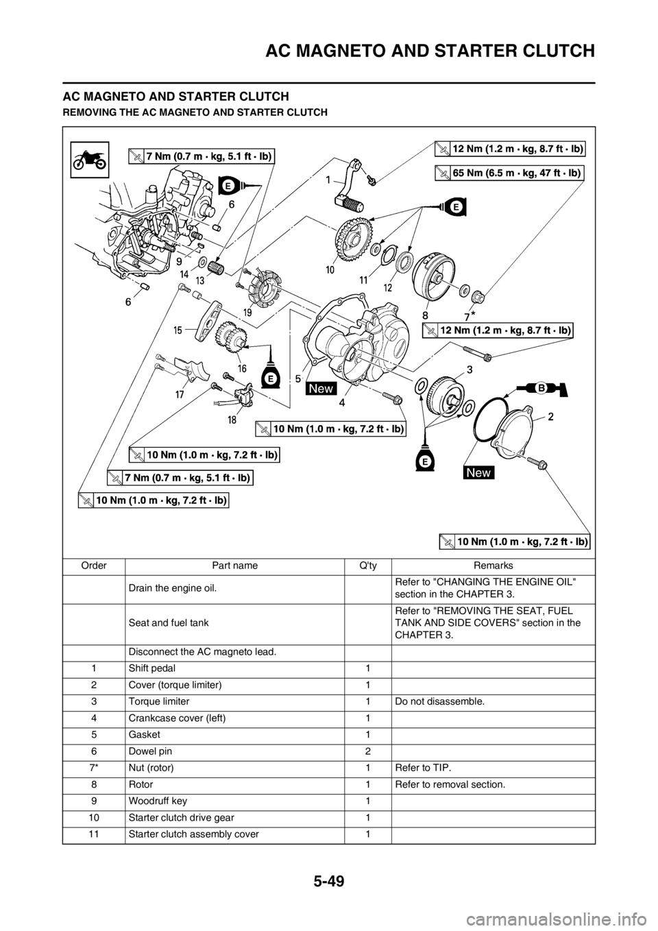
AC MAGNETO AND STARTER CLUTCH
REMOVING THE AC MAGNETO AND STARTER CLUTCH
Order Part name Q'ty Remarks
Drain the engine oil.Refer to "CHANGING THE ENGINE OIL"
section in the CHAPTER 3.
Seat and fuel tankRefer to "REMOVING THE SEAT, FUEL
TANK AND SIDE COVERS" section in the
CHAPTER 3.
Disconnect the AC magneto lead.
1 Shift pedal 1
2 Cover (torque limiter) 1
3 Torque limiter 1 Do not disassemble.
4 Crankcase cover (left) 1
5 Gasket 1
6 Dowel pin 2
7* Nut (rotor) 1 Refer to TIP.
8 Rotor 1 Refer to removal section.
9 Woodruff key 1
10 Starter clutch drive gear 1
11 Starter clutch assembly cover 1