ECU YAMAHA WR 250F 2015 User Guide
[x] Cancel search | Manufacturer: YAMAHA, Model Year: 2015, Model line: WR 250F, Model: YAMAHA WR 250F 2015Pages: 430, PDF Size: 14.14 MB
Page 95 of 430

CABLE ROUTING DIAGRAM
2-40
1. Battery negative lead
2. Fuel hose
3. Fuel pump coupler
4. Fuel pump lead
5. Resistor
6. Resistor coupler
7. Battery positive lead
8. Lean angle sensor
9. Starter motor lead
10. Radiator fan motor relay (blue tape)
11. Main relay (red tape)
12. Wire harness
13. Ground lead coupler
14. Starter relay coupler
15. Starter relay
16. Cross member
17. Diode
18. Taillight lead
19. Clamp
20. Fuel tank
21. Damper
22. Rear frame
23. Side cover 6
24. Plastic locking tie
A. After connecting the fuel pump coupler, attach
the coupler cover.
B. Pass the fuel hose to the front of the battery.
C. Route the resistor lead to the outside of the leads.
D. Connect the battery positive lead to the starter re-
lay terminal (in the left side of the vehicle).
E. Insert the protruding end of the wire harness into
the battery bracket hole and holder plate hole.
F. After connecting the negative lead coupler, place
it on the right side of the battery.
G. After installing the plastic cover to the starter re-
lay, connect the starter relay coupler.
H. Route the diode under the cross member and
place it on top of the rear fender.
I. Secure the two ends of the taillight coupler with
the starter motor lead.
J. Route the taillight lead so that it does not slack at
the rear of the vehicle.
K. Clamp the taillight lead and insert the clip into the
rear fender. Clamp it so that the lock faces in-
ward, and then cut off the excess end.
L. Route the battery positive lead under the cross
member.
M. Lower end of the rear frame
N. Clamp it so that the lock of the plastic locking tie
faces downward, insert the end into the rear
frame and side cover 6, and then cut off the ex-
cess end. After cutting off the excess end, make
sure that the plastic locking tie does not protrude
from the lower end of the rear frame.
O. Clamp it so that the lock of the plastic locking tie
faces downward, and then pass the end between
the fuel hose and rear frame.
P. Clamp the wire harness at the position of the
white tape.
Page 113 of 430

PRE-OPERATION INSPECTION AND MAINTENANCE
3-9
EAS2GB2081
PRE-OPERATION INSPECTION AND MAINTENANCE
Before riding for break-in operation, practice or a race, make sure the machine is in good operating
condition.
Before using this machine, check the following points.
EAS2GB2082GENERAL INSPECTION AND MAINTENANCE
TIP
Perform usual maintenance enough so that, in the race course, a confirmation of that and simple set-
ting adjustments may only be left, in order to get enough time to use effectively.ITEM inspect Page
CoolantCheck that coolant is filled up to the radiator cap.
Check the cooling system for leakage.3-10 – 12
FuelCheck that a fresh gasoline is filled in the fuel tank.
Check the fuel line for leakage.1-32
Engine oilCheck that the oil level is correct. Check the crank-
case and oil line for leakage.3-16 – 18
Gear shifter and clutchCheck that gears can be shifted correctly in order and
that the clutch operates smoothly.3-12 – 13
Throttle grip/HousingCheck that the throttle grip operation and free play
are correctly adjusted. Lubricate the throttle grip and
housing, if necessary.3-13 – 14
BrakesCheck the play of front brake and effect of front and
rear brake.3-24 – 30
Drive chainCheck drive chain slack and alignment. Check that
the drive chain is lubricated properly.3-30
5-68 – 69
WheelsCheck for excessive wear and tire pressure. Check
for loose spokes and have no excessive play.3-35 – 36
SteeringCheck that the handlebar can be turned smoothly and
have no excessive play.3-36 – 37
Front forks and rear
shock absorberCheck that they operate smoothly and there is no oil
leakage.3-31 – 35
Cables (wires)Check that the clutch and throttle cables move
smoothly. Check that they are not caught when the
handlebars are turned or when the front forks travel
up and down.—
Exhaust pipeCheck that the exhaust pipe is tightly mounted and
has no cracks.3-15 – 16
Rear wheel sprocketCheck that the rear wheel sprocket tightening bolt is
not loose.5-10 – 11
LubricationCheck for smooth operation. Lubricate if necessary. 3-13
3-37 – 38
Bolts and nutsCheck the chassis and engine for loose bolts and
nuts.1-36 – 37
Lead connectorsCheck that the AC magneto, ECU and ignition coil are
connected tightly.1-11 – 14
SettingsIs the machine set suitably for the condition of the rac-
ing course and weather or by taking into account the
results of test runs before racing? Are inspection and
maintenance completely done?4-1 – 8
Page 123 of 430
ENGINE
3-19
4. Measure:
• Engine idling speed
Out of specification Regulate.
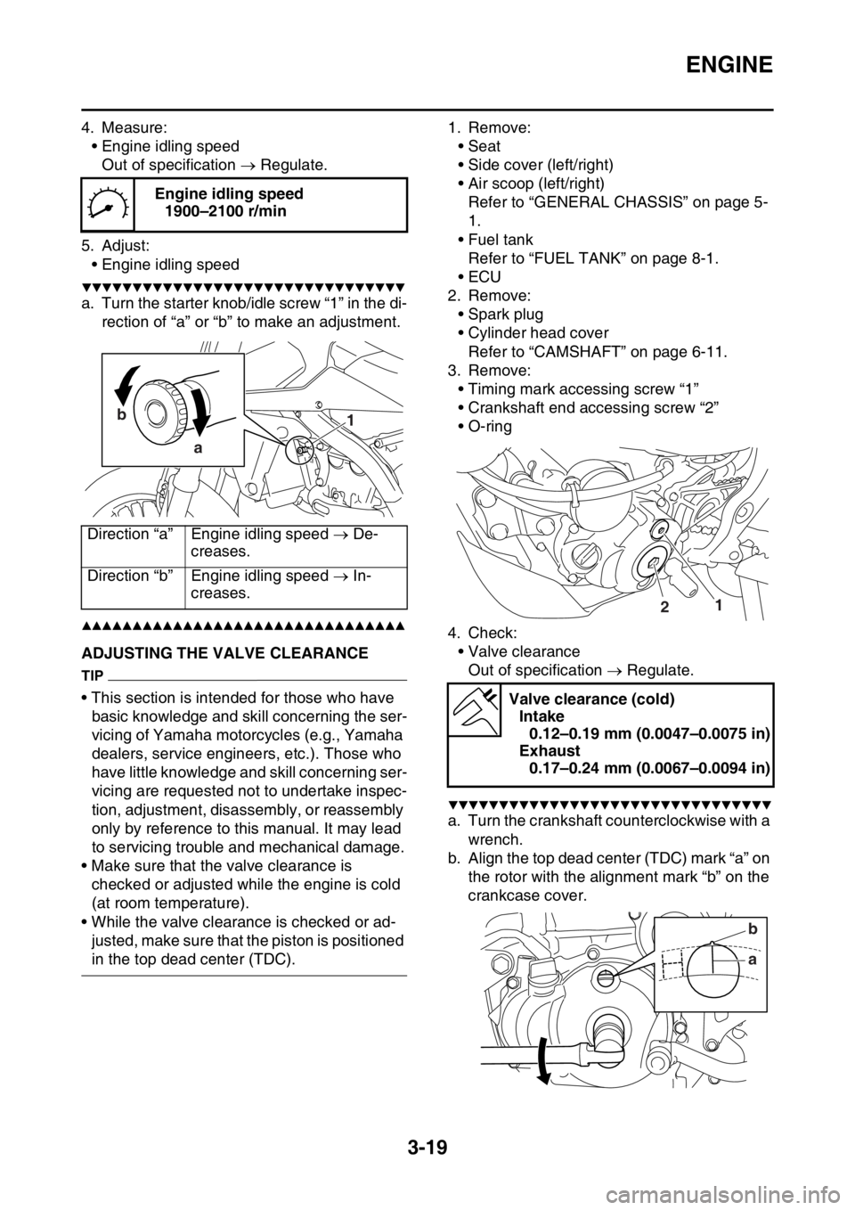
5. Adjust:
• Engine idling speed
▼▼▼▼▼▼▼▼▼▼▼▼▼▼▼▼▼▼▼▼▼▼▼▼▼▼▼▼▼▼▼▼
a. Turn the starter knob/idle screw “1” in the di-
rection of “a” or “b” to make an adjustment.
▲▲▲▲▲▲▲▲▲▲▲▲▲▲▲▲▲▲▲▲▲▲▲▲▲▲▲▲▲▲▲▲
EAS2GB2101ADJUSTING THE VALVE CLEARANCE
TIP
• This section is intended for those who have
basic knowledge and skill concerning the ser-
vicing of Yamaha motorcycles (e.g., Yamaha
dealers, service engineers, etc.). Those who
have little knowledge and skill concerning ser-
vicing are requested not to undertake inspec-
tion, adjustment, disassembly, or reassembly
only by reference to this manual. It may lead
to servicing trouble and mechanical damage.
• Make sure that the valve clearance is
checked or adjusted while the engine is cold
(at room temperature).
• While the valve clearance is checked or ad-
justed, make sure that the piston is positioned
in the top dead center (TDC).1. Remove:
• Seat
• Side cover (left/right)
• Air scoop (left/right)
Refer to “GENERAL CHASSIS” on page 5-
1.
• Fuel tank
Refer to “FUEL TANK” on page 8-1.
•ECU
2. Remove:
• Spark plug
• Cylinder head cover
Refer to “CAMSHAFT” on page 6-11.
3. Remove:
• Timing mark accessing screw “1”
• Crankshaft end accessing screw “2”
• O-ring
4. Check:
• Valve clearance
Out of specification Regulate.
▼▼▼▼▼▼▼▼▼▼▼▼▼▼▼▼▼▼▼▼▼▼▼▼▼▼▼▼▼▼▼▼
a. Turn the crankshaft counterclockwise with a
wrench.
b. Align the top dead center (TDC) mark “a” on
the rotor with the alignment mark “b” on the
crankcase cover. Engine idling speed
1900–2100 r/min
Direction “a” Engine idling speed De-
creases.
Direction “b” Engine idling speed In-
creases.
1 b
a
Valve clearance (cold)
Intake
0.12–0.19 mm (0.0047–0.0075 in)
Exhaust
0.17–0.24 mm (0.0067–0.0094 in)
12
ab
Page 128 of 430
CHASSIS
3-24
EAS2GB2103
CHASSIS
EAS2GB2104BLEEDING THE BRAKE SYSTEMEWA
WARNING
Bleed the brake system whenever:
• The system is disassembled.
• A brake hose is loosened, disconnected,
or replaced.
• The brake fluid level is very low.
• Brake operation is faulty.
1. Remove:
• Brake master cylinder cap
• Reservoir diaphragm
• Reservoir float (front brake)
• Protector (rear brake)
TIP
• Be careful not to spill any brake fluid or allow
the reservoir to overflow.
• Make sure that there is enough brake fluid be-
fore applying the brake. Ignoring this precau-
tion could allow air to enter the brake system,
considerably lengthening the bleeding proce-
dure.
• If bleeding is difficult, it may be necessary to
let the brake fluid settle for a few hours. Re-
peat the bleeding procedure when the tiny
bubbles in the hose have disappeared.
2. Bleed the brake system.
▼▼▼▼▼▼▼▼▼▼▼▼▼▼▼▼▼▼▼▼▼▼▼▼▼▼▼▼▼▼▼▼
a. Fill the reservoir to the proper level with the
recommended brake fluid.
b. Install the reservoir diaphragm.
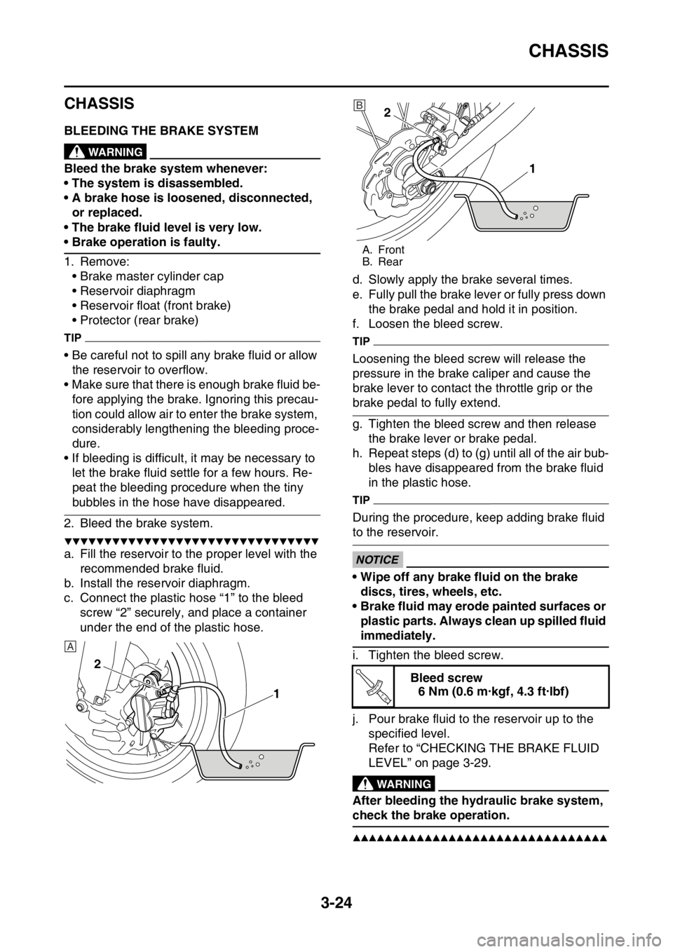
c. Connect the plastic hose “1” to the bleed
screw “2” securely, and place a container
under the end of the plastic hose.d. Slowly apply the brake several times.
e. Fully pull the brake lever or fully press down
the brake pedal and hold it in position.
f. Loosen the bleed screw.
TIP
Loosening the bleed screw will release the
pressure in the brake caliper and cause the
brake lever to contact the throttle grip or the
brake pedal to fully extend.
g. Tighten the bleed screw and then release
the brake lever or brake pedal.
h. Repeat steps (d) to (g) until all of the air bub-
bles have disappeared from the brake fluid
in the plastic hose.
TIP
During the procedure, keep adding brake fluid
to the reservoir.
ECA
NOTICE
• Wipe off any brake fluid on the brake
discs, tires, wheels, etc.
• Brake fluid may erode painted surfaces or
plastic parts. Always clean up spilled fluid
immediately.
i. Tighten the bleed screw.
j. Pour brake fluid to the reservoir up to the
specified level.
Refer to “CHECKING THE BRAKE FLUID
LEVEL” on page 3-29.
EWA
WARNING
After bleeding the hydraulic brake system,
check the brake operation.
▲▲▲▲▲▲▲▲▲▲▲▲▲▲▲▲▲▲▲▲▲▲▲▲▲▲▲▲▲▲▲▲
1 2
A
A. Front
B. Rear
Bleed screw
6 Nm (0.6 m·kgf, 4.3 ft·lbf)
2
1B
T R..
Page 134 of 430

CHASSIS
3-30
EWA
WARNING
• Use only the designated brake fluid. Other
brake fluids may cause the rubber seals to
deteriorate, causing leakage and poor
brake performance.
• Refill with the same type of brake fluid that
is already in the system. Mixing brake flu-
ids may result in a harmful chemical reac-
tion, leading to poor brake performance.
• When refilling, be careful that water does
not enter the brake fluid reservoir. Water
will significantly lower the boiling point of
the brake fluid and could cause vapor
lock.
ECA
NOTICE
Brake fluid may damage painted surfaces
and plastic parts. Therefore, always clean
up any spilt brake fluid immediately.
EAS2GB2112ADJUSTING THE DRIVE CHAIN SLACKECA
NOTICE
A drive chain that is too tight will overload
the engine and other vital parts, and one
that is too loose can skip and damage the
swingarm or cause an accident. Therefore,
keep the drive chain slack within the speci-
fied limits.
1. Use a suitable stand to raise the rear wheel
off the ground.
EWA
WARNING
Securely support the vehicle so that there is
no danger of it falling over.
2. Shift the transmission into the neutral posi-
tion.
3. Pull the drive chain up above the drive chain
guide installation bolt with a force of about
50 N (5.0 kgf, 36 lbf).
4. Check:
• Drive chain slack “a”
Out of specification Regulate.
TIP
Measure drive chain slack between the drive
chain guide and the bottom of the chain as
shown.5. Adjust:
• Drive chain slack
▼▼▼▼▼▼▼▼▼▼▼▼▼▼▼▼▼▼▼▼▼▼▼▼▼▼▼▼▼▼▼▼
a. Loosen the wheel axle nut “1”.
b. Loosen both locknuts “2”.
c. Turn the adjusting bolt “3” in direction “a” or
“b” until the specified drive chain slack is ob-
tained.
TIP
• To maintain the proper wheel alignment, ad-
just both sides evenly.
• Push the rear wheel forward to make sure that
there is no clearance between the swingarm
end plates and the ends of the swingarm.
d. Tighten the locknut.
e. Tighten the wheel axle nut.
▲▲▲▲▲▲▲▲▲▲▲▲▲▲▲▲▲▲▲▲▲▲▲▲▲▲▲▲▲▲▲▲
Drive chain slack
50–60 mm (1.97–2.36 in)
Direction “a”
The drive chain slack decreases.
Direction “b”
The drive chain slack increases.
Locknut
21 Nm (2.1 m·kgf, 15 ft·lbf)
Wheel axle nut
125 Nm (12.5 m·kgf, 90 ft·lbf)
a
1
32
a
b
T R..
T R..
Page 135 of 430
CHASSIS
3-31
EAS2GB2113CHECKING THE FRONT FORK LEGS
1. Stand the vehicle upright on a level surface.
EWA
WARNING
Securely support the vehicle so that there is
no danger of it falling over.
2. Check:
• Inner tube
Damage/scratches Replace.
• Front fork leg (s)
Oil leaks between inner tube and outer tube
Replace the oil seal.
3. Hold the vehicle upright and apply the front
brake.
4. Check:
• Front fork operation
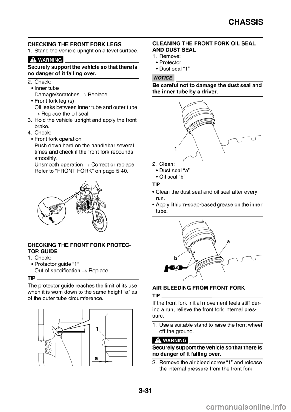
Push down hard on the handlebar several
times and check if the front fork rebounds
smoothly.
Unsmooth operation Correct or replace.
Refer to “FRONT FORK” on page 5-40.
EAS2GB2114CHECKING THE FRONT FORK PROTEC-
TOR GUIDE
1. Check:
• Protector guide “1”
Out of specification Replace.
TIP
The protector guide reaches the limit of its use
when it is worn down to the same height “a” as
of the outer tube circumference.
EAS2GB2115
CLEANING THE FRONT FORK OIL SEAL
AND DUST SEAL
1. Remove:
•Protector
• Dust seal “1”
ECA
NOTICE
Be careful not to damage the dust seal and
the inner tube by a driver.
2. Clean:
• Dust seal “a”
• Oil seal “b”
TIP
• Clean the dust seal and oil seal after every
run.
• Apply lithium-soap-based grease on the inner
tube.
EAS2GB2116AIR BLEEDING FROM FRONT FORK
TIP
If the front fork initial movement feels stiff dur-
ing a run, relieve the front fork internal pres-
sure.
1. Use a suitable stand to raise the front wheel
off the ground.
EWA
WARNING
Securely support the vehicle so that there is
no danger of it falling over.
2. Remove the air bleed screw “1” and release
the internal pressure from the front fork.
1
a
1
LS
a
b
Page 136 of 430
CHASSIS
3-32
3. Tighten:
• Air bleed screw
EAS2GB2117ADJUSTING THE FRONT FORK LEGSEWA
WARNING
• Always adjust the left and right front forks
evenly. If this is not done, the vehicle may
have poor stability.
• Securely support the vehicle so that there
is no danger of it falling over.
Rebound damping force
ECA
NOTICE
Do not turn the adjuster forcibly beyond its
adjusting range.
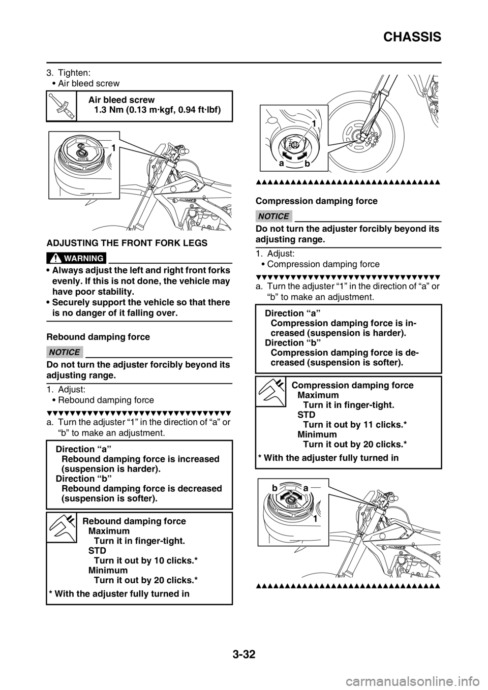
1. Adjust:
• Rebound damping force
▼▼▼▼▼▼▼▼▼▼▼▼▼▼▼▼▼▼▼▼▼▼▼▼▼▼▼▼▼▼▼▼
a. Turn the adjuster “1” in the direction of “a” or
“b” to make an adjustment.
▲▲▲▲▲▲▲▲▲▲▲▲▲▲▲▲▲▲▲▲▲▲▲▲▲▲▲▲▲▲▲▲
Compression damping forceECA
NOTICE
Do not turn the adjuster forcibly beyond its
adjusting range.
1. Adjust:
• Compression damping force
▼▼▼▼▼▼▼▼▼▼▼▼▼▼▼▼▼▼▼▼▼▼▼▼▼▼▼▼▼▼▼▼
a. Turn the adjuster “1” in the direction of “a” or
“b” to make an adjustment.
▲▲▲▲▲▲▲▲▲▲▲▲▲▲▲▲▲▲▲▲▲▲▲▲▲▲▲▲▲▲▲▲
Air bleed screw
1.3 Nm (0.13 m·kgf, 0.94 ft·lbf)
Direction “a”
Rebound damping force is increased
(suspension is harder).
Direction “b”
Rebound damping force is decreased
(suspension is softer).
Rebound damping force
Maximum
Turn it in finger-tight.
STD
Turn it out by 10 clicks.*
Minimum
Turn it out by 20 clicks.*
* With the adjuster fully turned in
T R..
1
Direction “a”
Compression damping force is in-
creased (suspension is harder).
Direction “b”
Compression damping force is de-
creased (suspension is softer).
Compression damping force
Maximum
Turn it in finger-tight.
STD
Turn it out by 11 clicks.*
Minimum
Turn it out by 20 clicks.*
* With the adjuster fully turned in
1
a
b
a b
1
Page 137 of 430
CHASSIS
3-33
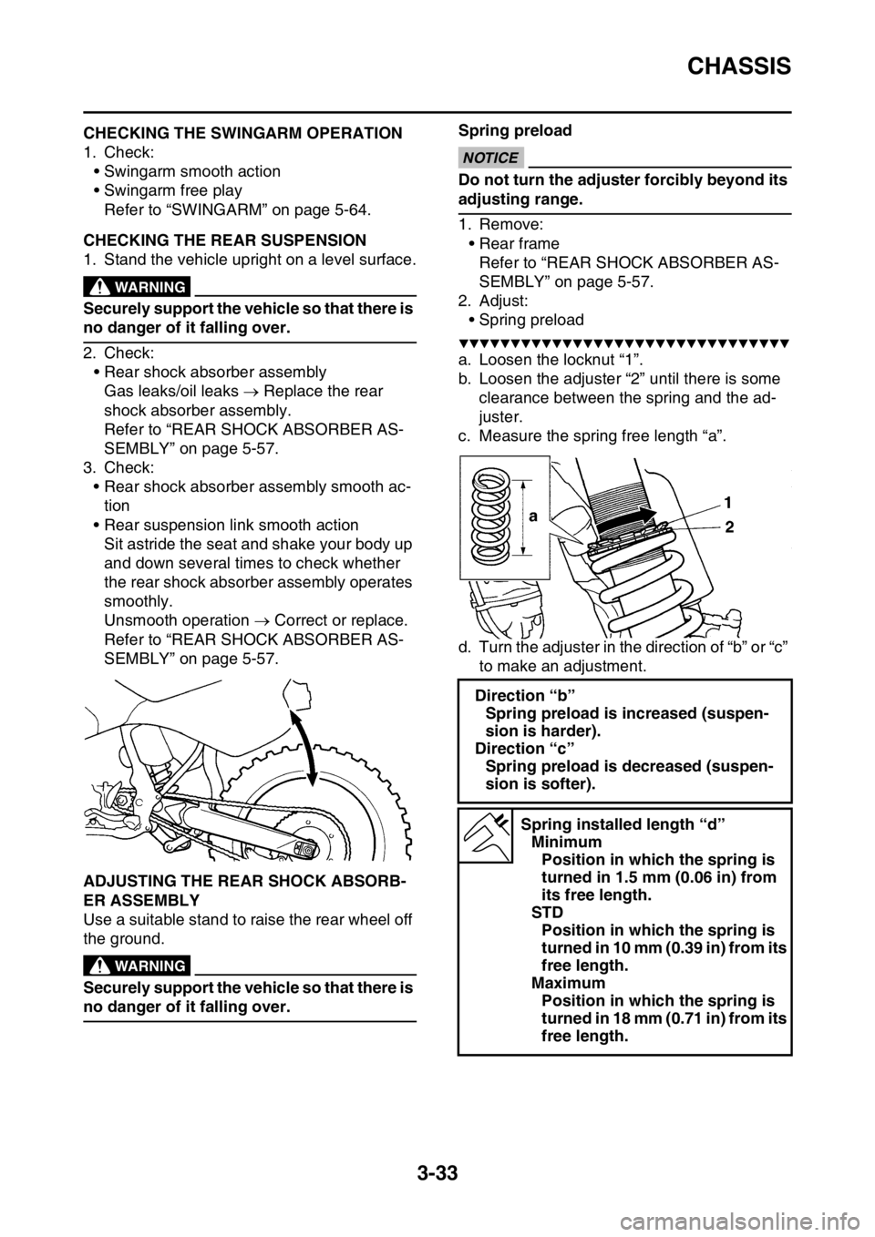
EAS2GB2118CHECKING THE SWINGARM OPERATION
1. Check:
• Swingarm smooth action
• Swingarm free play
Refer to “SWINGARM” on page 5-64.
EAS2GB2119CHECKING THE REAR SUSPENSION
1. Stand the vehicle upright on a level surface.
EWA
WARNING
Securely support the vehicle so that there is
no danger of it falling over.
2. Check:
• Rear shock absorber assembly
Gas leaks/oil leaks Replace the rear
shock absorber assembly.
Refer to “REAR SHOCK ABSORBER AS-
SEMBLY” on page 5-57.
3. Check:
• Rear shock absorber assembly smooth ac-
tion
• Rear suspension link smooth action
Sit astride the seat and shake your body up
and down several times to check whether
the rear shock absorber assembly operates
smoothly.
Unsmooth operation Correct or replace.
Refer to “REAR SHOCK ABSORBER AS-
SEMBLY” on page 5-57.
EAS2GB2120ADJUSTING THE REAR SHOCK ABSORB-
ER ASSEMBLY
Use a suitable stand to raise the rear wheel off
the ground.
EWA
WARNING
Securely support the vehicle so that there is
no danger of it falling over.Spring preload
ECA
NOTICE
Do not turn the adjuster forcibly beyond its
adjusting range.
1. Remove:
• Rear frame
Refer to “REAR SHOCK ABSORBER AS-
SEMBLY” on page 5-57.
2. Adjust:
• Spring preload
▼▼▼▼▼▼▼▼▼▼▼▼▼▼▼▼▼▼▼▼▼▼▼▼▼▼▼▼▼▼▼▼
a. Loosen the locknut “1”.
b. Loosen the adjuster “2” until there is some
clearance between the spring and the ad-
juster.
c. Measure the spring free length “a”.
d. Turn the adjuster in the direction of “b” or “c”
to make an adjustment.
Direction “b”
Spring preload is increased (suspen-
sion is harder).
Direction “c”
Spring preload is decreased (suspen-
sion is softer).
Spring installed length “d”
Minimum
Position in which the spring is
turned in 1.5 mm (0.06 in) from
its free length.
STD
Position in which the spring is
turned in 10 mm (0.39 in) from its
free length.
Maximum
Position in which the spring is
turned in 18 mm (0.71 in) from its
free length.
Page 140 of 430
CHASSIS
3-36
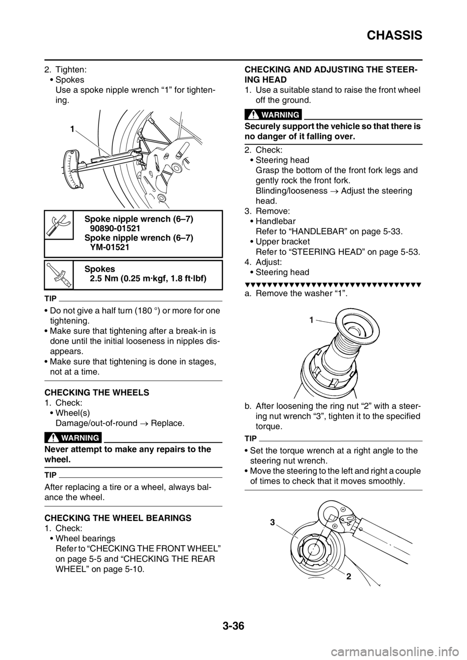
2. Tighten:
• Spokes
Use a spoke nipple wrench “1” for tighten-
ing.
TIP
• Do not give a half turn (180 °) or more for one
tightening.
• Make sure that tightening after a break-in is
done until the initial looseness in nipples dis-
appears.
• Make sure that tightening is done in stages,
not at a time.
EAS2GB2123CHECKING THE WHEELS
1. Check:
• Wheel(s)
Damage/out-of-round Replace.
EWA
WARNING
Never attempt to make any repairs to the
wheel.
TIP
After replacing a tire or a wheel, always bal-
ance the wheel.
EAS2GB2124CHECKING THE WHEEL BEARINGS
1. Check:
• Wheel bearings
Refer to “CHECKING THE FRONT WHEEL”
on page 5-5 and “CHECKING THE REAR
WHEEL” on page 5-10.
EAS2GB2125
CHECKING AND ADJUSTING THE STEER-
ING HEAD
1. Use a suitable stand to raise the front wheel
off the ground.
EWA
WARNING
Securely support the vehicle so that there is
no danger of it falling over.
2. Check:
• Steering head
Grasp the bottom of the front fork legs and
gently rock the front fork.
Blinding/looseness Adjust the steering
head.
3. Remove:
• Handlebar
Refer to “HANDLEBAR” on page 5-33.
• Upper bracket
Refer to “STEERING HEAD” on page 5-53.
4. Adjust:
• Steering head
▼▼▼▼▼▼▼▼▼▼▼▼▼▼▼▼▼▼▼▼▼▼▼▼▼▼▼▼▼▼▼▼
a. Remove the washer “1”.
b. After loosening the ring nut “2” with a steer-
ing nut wrench “3”, tighten it to the specified
torque.
TIP
• Set the torque wrench at a right angle to the
steering nut wrench.
• Move the steering to the left and right a couple
of times to check that it moves smoothly. Spoke nipple wrench (6–7)
90890-01521
Spoke nipple wrench (6–7)
YM-01521
Spokes
2.5 Nm (0.25 m·kgf, 1.8 ft·lbf)
1
T R..
1
3
2
Page 163 of 430
FRONT WHEEL
5-5
EAS2GB2157REMOVING THE FRONT WHEEL
1. Use a suitable stand to raise the front wheel
off the ground.
EWA
WARNING
Securely support the vehicle so that there is
no danger of it falling over.
2. Remove:
• Front wheel
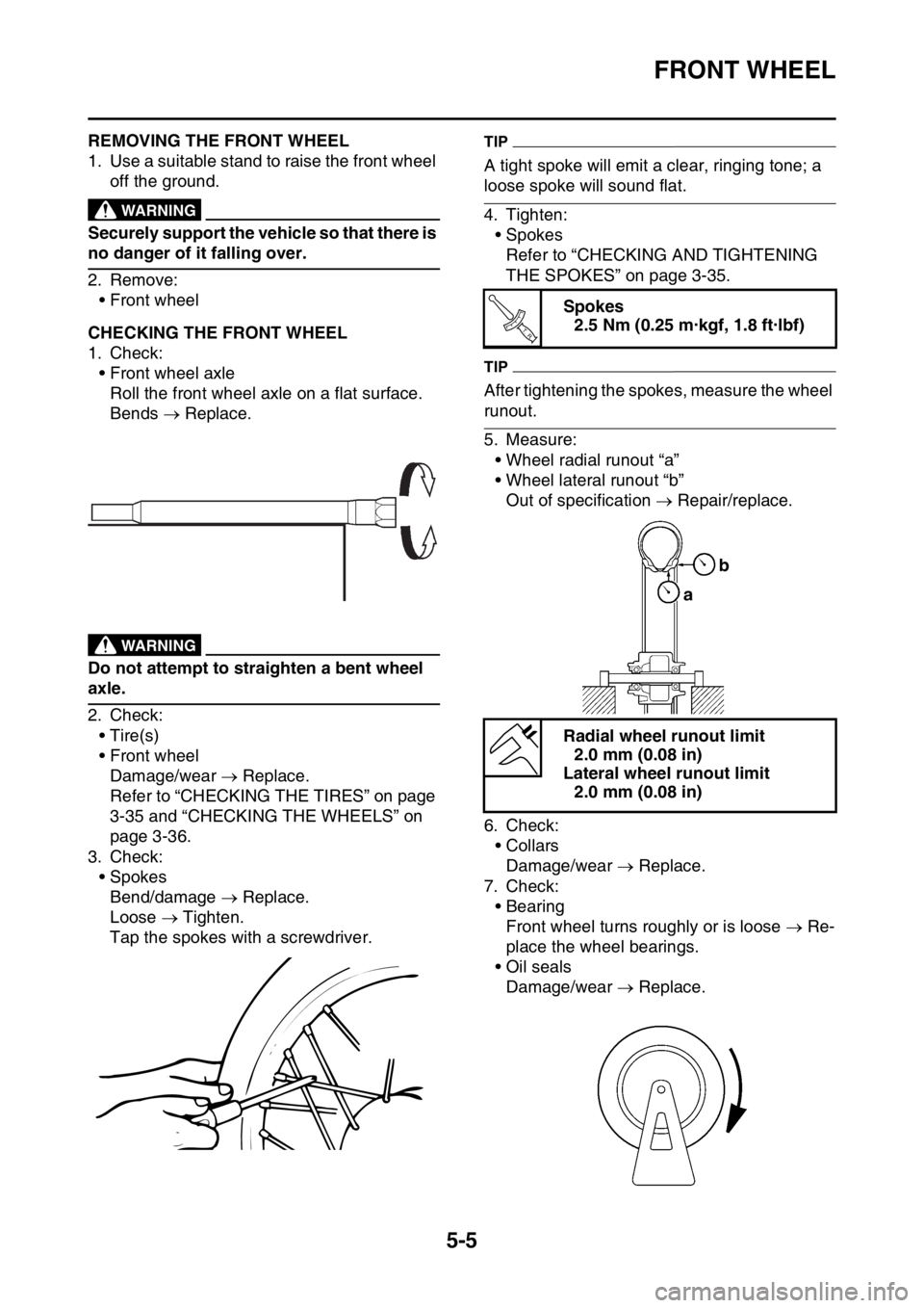
EAS2GB2158CHECKING THE FRONT WHEEL
1. Check:
• Front wheel axle
Roll the front wheel axle on a flat surface.
Bends Replace.
EWA
WARNING
Do not attempt to straighten a bent wheel
axle.
2. Check:
•Tire(s)
• Front wheel
Damage/wear Replace.
Refer to “CHECKING THE TIRES” on page
3-35 and “CHECKING THE WHEELS” on
page 3-36.
3. Check:
• Spokes
Bend/damage Replace.
Loose Tighten.
Tap the spokes with a screwdriver.
TIP
A tight spoke will emit a clear, ringing tone; a
loose spoke will sound flat.
4. Tighten:
• Spokes
Refer to “CHECKING AND TIGHTENING
THE SPOKES” on page 3-35.
TIP
After tightening the spokes, measure the wheel
runout.
5. Measure:
• Wheel radial runout “a”
• Wheel lateral runout “b”
Out of specification Repair/replace.
6. Check:
•Collars
Damage/wear Replace.
7. Check:
• Bearing
Front wheel turns roughly or is loose Re-
place the wheel bearings.
• Oil seals
Damage/wear Replace.
Spokes
2.5 Nm (0.25 m·kgf, 1.8 ft·lbf)
Radial wheel runout limit
2.0 mm (0.08 in)
Lateral wheel runout limit
2.0 mm (0.08 in)
T R..
ab