ECU YAMAHA WR 250F 2015 Owner's Guide
[x] Cancel search | Manufacturer: YAMAHA, Model Year: 2015, Model line: WR 250F, Model: YAMAHA WR 250F 2015Pages: 430, PDF Size: 14.14 MB
Page 326 of 430

FUEL TANK
8-5
TIP
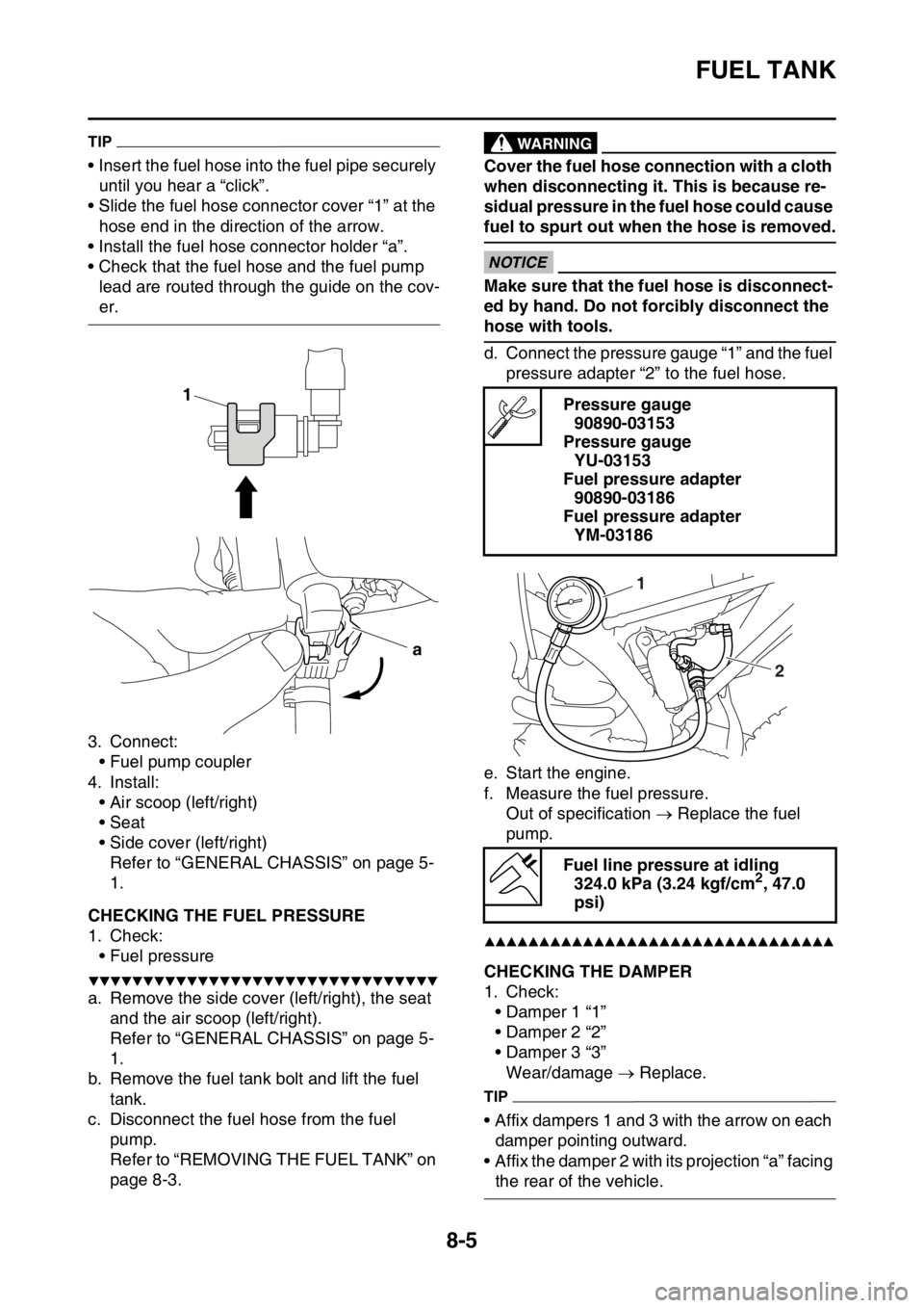
• Insert the fuel hose into the fuel pipe securely
until you hear a “click”.
• Slide the fuel hose connector cover “1” at the
hose end in the direction of the arrow.
• Install the fuel hose connector holder “a”.
• Check that the fuel hose and the fuel pump
lead are routed through the guide on the cov-
er.
3. Connect:
• Fuel pump coupler
4. Install:
• Air scoop (left/right)
• Seat
• Side cover (left/right)
Refer to “GENERAL CHASSIS” on page 5-
1.
EAS2GB2350CHECKING THE FUEL PRESSURE
1. Check:
• Fuel pressure
▼▼▼▼▼▼▼▼▼▼▼▼▼▼▼▼▼▼▼▼▼▼▼▼▼▼▼▼▼▼▼▼
a. Remove the side cover (left/right), the seat
and the air scoop (left/right).
Refer to “GENERAL CHASSIS” on page 5-
1.
b. Remove the fuel tank bolt and lift the fuel
tank.
c. Disconnect the fuel hose from the fuel
pump.
Refer to “REMOVING THE FUEL TANK” on
page 8-3.
EWA
WARNING
Cover the fuel hose connection with a cloth
when disconnecting it. This is because re-
sidual pressure in the fuel hose could cause
fuel to spurt out when the hose is removed.
ECA
NOTICE
Make sure that the fuel hose is disconnect-
ed by hand. Do not forcibly disconnect the
hose with tools.
d. Connect the pressure gauge “1” and the fuel
pressure adapter “2” to the fuel hose.
e. Start the engine.
f. Measure the fuel pressure.
Out of specification Replace the fuel
pump.
▲▲▲▲▲▲▲▲▲▲▲▲▲▲▲▲▲▲▲▲▲▲▲▲▲▲▲▲▲▲▲▲
EAS2GB2351CHECKING THE DAMPER
1. Check:
• Damper 1 “1”
• Damper 2 “2”
• Damper 3 “3”
Wear/damage Replace.
TIP
• Affix dampers 1 and 3 with the arrow on each
damper pointing outward.
• Affix the damper 2 with its projection “a” facing
the rear of the vehicle.
1
a
Pressure gauge
90890-03153
Pressure gauge
YU-03153
Fuel pressure adapter
90890-03186
Fuel pressure adapter
YM-03186
Fuel line pressure at idling
324.0 kPa (3.24 kgf/cm
2, 47.0
psi)
1
2
Page 328 of 430

THROTTLE BODY
8-7
EAS2GB2353
THROTTLE BODY
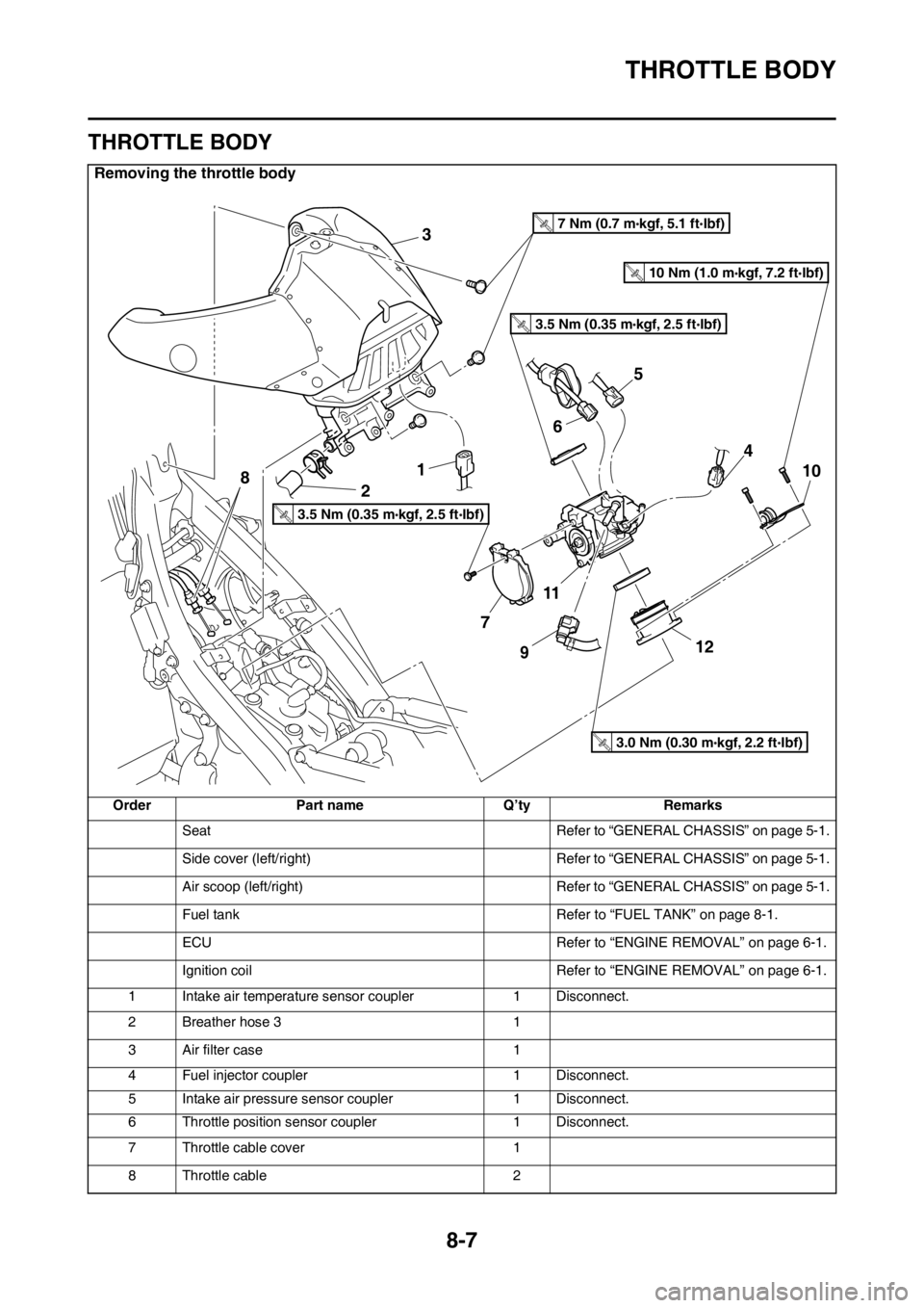
Removing the throttle body
Order Part name Q’ty Remarks
Seat Refer to “GENERAL CHASSIS” on page 5-1.
Side cover (left/right) Refer to “GENERAL CHASSIS” on page 5-1.
Air scoop (left/right) Refer to “GENERAL CHASSIS” on page 5-1.
Fuel tank Refer to “FUEL TANK” on page 8-1.
ECU Refer to “ENGINE REMOVAL” on page 6-1.
Ignition coil Refer to “ENGINE REMOVAL” on page 6-1.
1 Intake air temperature sensor coupler 1 Disconnect.
2 Breather hose 3 1
3 Air filter case 1
4 Fuel injector coupler 1 Disconnect.
5 Intake air pressure sensor coupler 1 Disconnect.
6 Throttle position sensor coupler 1 Disconnect.
7 Throttle cable cover 1
8 Throttle cable 2
3
1
2
7
11
12
10
9
4
8
6
5
3.5 Nm (0.35 m kgf, 2.5 ft Ibf)T.R.
3.5 Nm (0.35 m kgf, 2.5 ft Ibf)T.R.
7 Nm (0.7 m kgf, 5.1 ft Ibf)T.R.
3.0 Nm (0.30 m kgf, 2.2 ft Ibf)T.R.
10 Nm (1.0 m kgf, 7.2 ft Ibf)T.R.
Page 333 of 430

9
ELECTRICAL SYSTEM
IGNITION SYSTEM.......................................................................................... 9-2
CIRCUIT DIAGRAM ................................................................................... 9-2
TROUBLESHOOTING ............................................................................... 9-4
ELECTRIC STARTING SYSTEM..................................................................... 9-6
CIRCUIT DIAGRAM ................................................................................... 9-6
STARTING CIRCUIT CUT-OFF SYSTEM OPERATION ........................... 9-8
TROUBLESHOOTING ............................................................................. 9-10
CHARGING SYSTEM..................................................................................... 9-12
CIRCUIT DIAGRAM ................................................................................. 9-12
TROUBLESHOOTING ............................................................................. 9-14
LIGHTING SYSTEM....................................................................................... 9-16
CIRCUIT DIAGRAM ................................................................................. 9-16
TROUBLESHOOTING ............................................................................. 9-18
SIGNALING SYSTEM.................................................................................... 9-20
CIRCUIT DIAGRAM ................................................................................. 9-20
TROUBLESHOOTING ............................................................................. 9-22
COOLING SYSTEM........................................................................................ 9-24
CIRCUIT DIAGRAM ................................................................................. 9-24
TROUBLESHOOTING ............................................................................. 9-26
FUEL INJECTION SYSTEM........................................................................... 9-28
CIRCUIT DIAGRAM ................................................................................. 9-28
ECU SELF-DIAGNOSTIC FUNCTION ..................................................... 9-30
TROUBLESHOOTING METHOD ............................................................. 9-31
YAMAHA DIAGNOSTIC TOOL ................................................................ 9-32
TROUBLESHOOTING DETAILS ............................................................. 9-35
FUEL PUMP SYSTEM.................................................................................... 9-56
CIRCUIT DIAGRAM ................................................................................. 9-56
TROUBLESHOOTING ............................................................................. 9-58
Page 337 of 430

IGNITION SYSTEM
9-3
1. Joint connector
2. Joint connector
4. AC magneto
9. Battery
10.Frame ground
11.Starter relay
12.Main fuse
22.ECU (engine control unit)
23.Ignition coil
24.Spark plug
30.Joint connector
35.Lean angle sensor
36.Engine stop switch
48.Frame ground
Page 339 of 430

IGNITION SYSTEM
9-5
8. Check the lean angle sensor.
Refer to “CHECKING THE LEAN
ANGLE SENSOR” on page 9-75.NG
Replace the lean angle sensor.
OK
9. Check the entire ignition system’s
wiring.
Refer to “CIRCUIT DIAGRAM” on
page 9-2.NG
Properly connect or repair the ignition sys-
tem’s wiring.
OK
Replace the ECU.
Page 341 of 430

ELECTRIC STARTING SYSTEM
9-7
1. Joint connector
2. Joint connector
3. Joint connector
7. Main relay
9. Battery
10.Frame ground
11.Starter relay
12.Main fuse
13.Starter motor
14.Starter relay diode
22.ECU (engine control unit)
30.Joint connector
36.Engine stop switch
37.Neutral switch
38.Diode
39.Starting circuit cut-off relay
40.Clutch switch
41.Start switch
48.Frame ground
Page 345 of 430

ELECTRIC STARTING SYSTEM
9-11
8. Check the main relay.
Refer to “CHECKING THE RE-
LAYS” on page 9-72.NG
Replace the main relay.
OK
9. Check the neutral switch.
Refer to “CHECKING THE
SWITCHES” on page 9-64.NG
Replace the neutral switch.
OK
10.Check the clutch switch.
Refer to “CHECKING THE
SWITCHES” on page 9-64.NG
Replace the clutch switch.
OK
11.Check the engine stop switch.
Refer to “CHECKING THE
SWITCHES” on page 9-64.NG
Replace the start switch.
OK
12.Check the start switch.
Refer to “CHECKING THE
SWITCHES” on page 9-64.NG
Replace the engine stop switch.
OK
13.Check the entire starting system’s
wiring.
Refer to “CIRCUIT DIAGRAM” on
page 9-6.NG
Properly connect or repair the starting sys-
tem’s wiring.
OK
Replace the ECU.
Page 351 of 430

LIGHTING SYSTEM
9-17
1. Joint connector
2. Joint connector
6. Headlight relay
7. Main relay
9. Battery
10.Frame ground
11.Starter relay
12.Main fuse
22.ECU (engine control unit)
30.Joint connector
42.Joint connector
43.Taillight
44.Headlight
47.Multi-function display
48.Frame ground
Page 352 of 430

LIGHTING SYSTEM
9-18
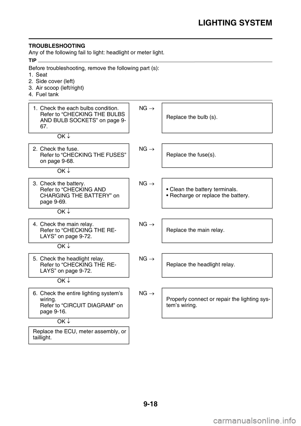
EAS2GB2368TROUBLESHOOTING
Any of the following fail to light: headlight or meter light.
TIP
Before troubleshooting, remove the following part (s):
1. Seat
2. Side cover (left)
3. Air scoop (left/right)
4. Fuel tank
1. Check the each bulbs condition.
Refer to “CHECKING THE BULBS
AND BULB SOCKETS” on page 9-
67.NG
Replace the bulb (s).
OK
2. Check the fuse.
Refer to “CHECKING THE FUSES”
on page 9-68.NG
Replace the fuse(s).
OK
3. Check the battery.
Refer to “CHECKING AND
CHARGING THE BATTERY” on
page 9-69.NG
• Clean the battery terminals.
• Recharge or replace the battery.
OK
4. Check the main relay.
Refer to “CHECKING THE RE-
LAYS” on page 9-72.NG
Replace the main relay.
OK
5. Check the headlight relay.
Refer to “CHECKING THE RE-
LAYS” on page 9-72.NG
Replace the headlight relay.
OK
6. Check the entire lighting system’s
wiring.
Refer to “CIRCUIT DIAGRAM” on
page 9-16.NG
Properly connect or repair the lighting sys-
tem’s wiring.
OK
Replace the ECU, meter assembly, or
taillight.
Page 355 of 430

SIGNALING SYSTEM
9-21
1. Joint connector
2. Joint connector
3. Joint connector
7. Main relay
9. Battery
10.Frame ground
11.Starter relay
12.Main fuse
15.Indicator light
17.Fuel level warning light
18.Resistor
19.Fuel sender
22.ECU (engine control unit)
30.Joint connector
42.Joint connector
46.Speed sensor
47.Multi-function display
48.Frame ground