ECU YAMAHA WR 250F 2015 Owner's Manual
[x] Cancel search | Manufacturer: YAMAHA, Model Year: 2015, Model line: WR 250F, Model: YAMAHA WR 250F 2015Pages: 430, PDF Size: 14.14 MB
Page 168 of 430
REAR WHEEL
5-10
EAS2GB2163REMOVING THE REAR WHEEL
1. Use a suitable stand to raise the rear wheel
off the ground.
EWA
WARNING
Securely support the vehicle so that there is
no danger of it falling over.
2. Remove:
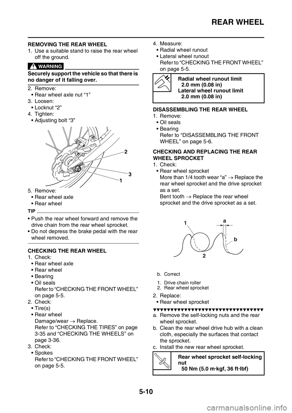
• Rear wheel axle nut “1”
3. Loosen:
• Locknut “2”
4. Tighten:
• Adjusting bolt “3”
5. Remove:
• Rear wheel axle
• Rear wheel
TIP
• Push the rear wheel forward and remove the
drive chain from the rear wheel sprocket.
• Do not depress the brake pedal with the rear
wheel removed.
EAS2GB2164CHECKING THE REAR WHEEL
1. Check:
• Rear wheel axle
• Rear wheel
• Bearing
• Oil seals
Refer to “CHECKING THE FRONT WHEEL”
on page 5-5.
2. Check:
•Tire(s)
• Rear wheel
Damage/wear Replace.
Refer to “CHECKING THE TIRES” on page
3-35 and “CHECKING THE WHEELS” on
page 3-36.
3. Check:
• Spokes
Refer to “CHECKING THE FRONT WHEEL”
on page 5-5.4. Measure:
• Radial wheel runout
• Lateral wheel runout
Refer to “CHECKING THE FRONT WHEEL”
on page 5-5.
EAS2GB2165DISASSEMBLING THE REAR WHEEL
1. Remove:
• Oil seals
• Bearing
Refer to “DISASSEMBLING THE FRONT
WHEEL” on page 5-6.
EAS2GB2166CHECKING AND REPLACING THE REAR
WHEEL SPROCKET
1. Check:
• Rear wheel sprocket
More than 1/4 tooth wear “a” Replace the
rear wheel sprocket and the drive sprocket
as a set.
Bent tooth Replace the rear wheel
sprocket and the drive sprocket as a set.
2. Replace:
• Rear wheel sprocket
▼▼▼▼▼▼▼▼▼▼▼▼▼▼▼▼▼▼▼▼▼▼▼▼▼▼▼▼▼▼▼▼
a. Remove the self-locking nuts and the rear
wheel sprocket.
b. Clean the rear wheel drive hub with a clean
cloth, especially the surfaces that contact
the sprocket.
c. Install the new rear wheel sprocket.
3
12
Radial wheel runout limit
2.0 mm (0.08 in)
Lateral wheel runout limit
2.0 mm (0.08 in)
b. Correct
1. Drive chain roller
2. Rear wheel sprocket
Rear wheel sprocket self-locking
nut
50 Nm (5.0 m·kgf, 36 ft·lbf)
T R..
Page 193 of 430
HANDLEBAR
5-35
EAS2GB2196REMOVING THE HANDLEBAR
1. Stand the vehicle on a level surface.
EWA
WARNING
Securely support the vehicle so that there is
no danger of it falling over.
2. Remove:
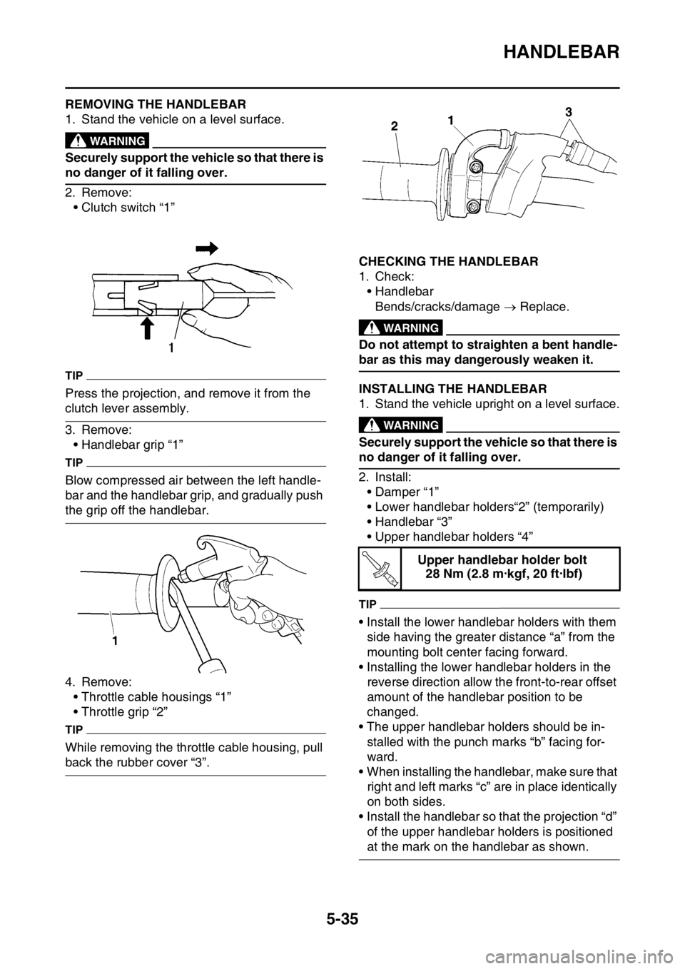
•Clutch switch “1”
TIP
Press the projection, and remove it from the
clutch lever assembly.
3. Remove:
• Handlebar grip “1”
TIP
Blow compressed air between the left handle-
bar and the handlebar grip, and gradually push
the grip off the handlebar.
4. Remove:
• Throttle cable housings “1”
• Throttle grip “2”
TIP
While removing the throttle cable housing, pull
back the rubber cover “3”.
EAS2GB2197CHECKING THE HANDLEBAR
1. Check:
• Handlebar
Bends/cracks/damage Replace.
EWA
WARNING
Do not attempt to straighten a bent handle-
bar as this may dangerously weaken it.
EAS2GB2198INSTALLING THE HANDLEBAR
1. Stand the vehicle upright on a level surface.
EWA
WARNING
Securely support the vehicle so that there is
no danger of it falling over.
2. Install:
• Damper “1”
• Lower handlebar holders“2” (temporarily)
• Handlebar “3”
• Upper handlebar holders “4”
TIP
• Install the lower handlebar holders with them
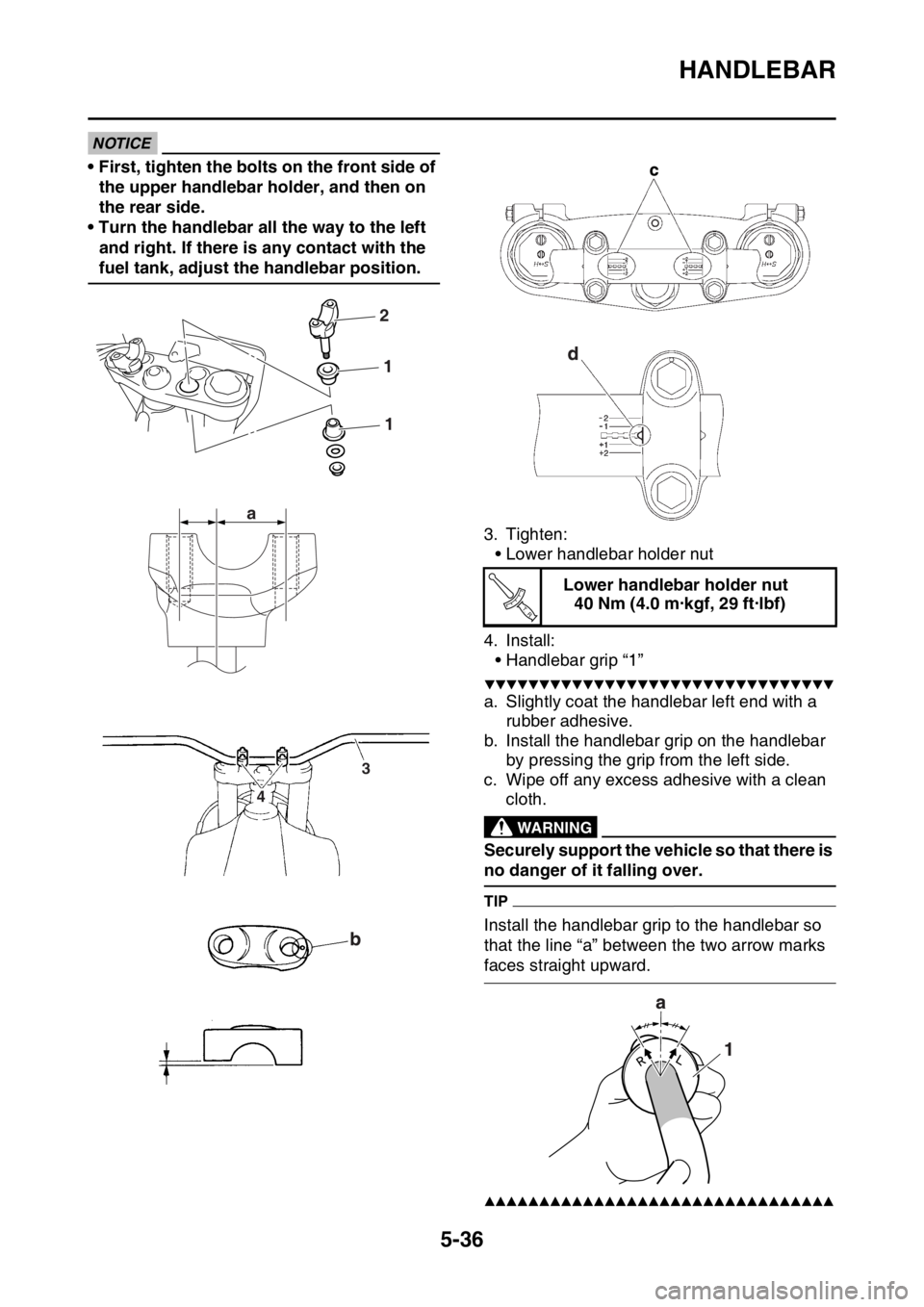
side having the greater distance “a” from the
mounting bolt center facing forward.
• Installing the lower handlebar holders in the
reverse direction allow the front-to-rear offset
amount of the handlebar position to be
changed.
• The upper handlebar holders should be in-
stalled with the punch marks “b” facing for-
ward.
• When installing the handlebar, make sure that
right and left marks “c” are in place identically
on both sides.
• Install the handlebar so that the projection “d”
of the upper handlebar holders is positioned
at the mark on the handlebar as shown.
ECA
Upper handlebar holder bolt
28 Nm (2.8 m·kgf, 20 ft·lbf)
T R..
Page 194 of 430
HANDLEBAR
5-36
NOTICE
• First, tighten the bolts on the front side of
the upper handlebar holder, and then on
the rear side.
• Turn the handlebar all the way to the left
and right. If there is any contact with the
fuel tank, adjust the handlebar position.
3. Tighten:
• Lower handlebar holder nut
4. Install:
• Handlebar grip “1”
▼▼▼▼▼▼▼▼▼▼▼▼▼▼▼▼▼▼▼▼▼▼▼▼▼▼▼▼▼▼▼▼
a. Slightly coat the handlebar left end with a
rubber adhesive.
b. Install the handlebar grip on the handlebar
by pressing the grip from the left side.
c. Wipe off any excess adhesive with a clean
cloth.
EWA
WARNING
Securely support the vehicle so that there is
no danger of it falling over.
TIP
Install the handlebar grip to the handlebar so
that the line “a” between the two arrow marks
faces straight upward.
▲▲▲▲▲▲▲▲▲▲▲▲▲▲▲▲▲▲▲▲▲▲▲▲▲▲▲▲▲▲▲▲
2
1
1
a
3
4
Lower handlebar holder nut
40 Nm (4.0 m·kgf, 29 ft·lbf)
T R..
Page 200 of 430
FRONT FORK
5-42
EAS2GB2200REMOVING THE FRONT FORK LEGS
1. Use a suitable stand to raise the front wheel
off the ground.
EWA
WARNING
Securely support the vehicle so that there is
no danger of it falling over.
TIP
Record the adjusting screw setting position be-
fore loosening the adjuster and the base valve.
2. Loosen:
• Upper bracket pinch bolts
• Damper assembly
• Lower bracket pinch bolts
EWA
WARNING
Before loosening the upper and lower
bracket pinch bolts, support the front fork
leg.
TIP
Before removing the front fork leg from the ve-
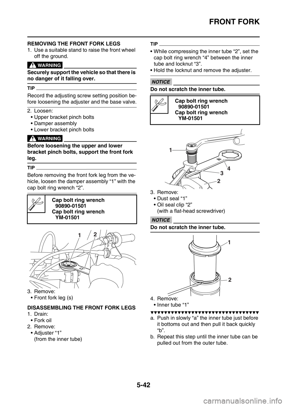
hicle, loosen the damper assembly “1” with the
cap bolt ring wrench “2”.
3. Remove:
• Front fork leg (s)
EAS2GB2201DISASSEMBLING THE FRONT FORK LEGS
1. Drain:
• Fork oil
2. Remove:
• Adjuster “1”
(from the inner tube)
TIP
• While compressing the inner tube “2”, set the
cap bolt ring wrench “4” between the inner
tube and locknut “3”.
• Hold the locknut and remove the adjuster.
ECA
NOTICE
Do not scratch the inner tube.
3. Remove:
• Dust seal “1”
• Oil seal clip “2”
(with a flat-head screwdriver)
ECA
NOTICE
Do not scratch the inner tube.
4. Remove:
• Inner tube “1”
▼▼▼▼▼▼▼▼▼▼▼▼▼▼▼▼▼▼▼▼▼▼▼▼▼▼▼▼▼▼▼▼
a. Push in slowly “a” the inner tube just before
it bottoms out and then pull it back quickly
“b”.
b. Repeat this step until the inner tube can be
pulled out from the outer tube. Cap bolt ring wrench
90890-01501
Cap bolt ring wrench
YM-01501
12
Cap bolt ring wrench
90890-01501
Cap bolt ring wrench
YM-01501
1
234
1
2
Page 212 of 430
STEERING HEAD
5-54
EAS2GB2206REMOVING THE LOWER BRACKET
1. Use a suitable stand to raise the front wheel
off the ground.
EWA
WARNING
Securely support the vehicle so that there is
no danger of it falling over.
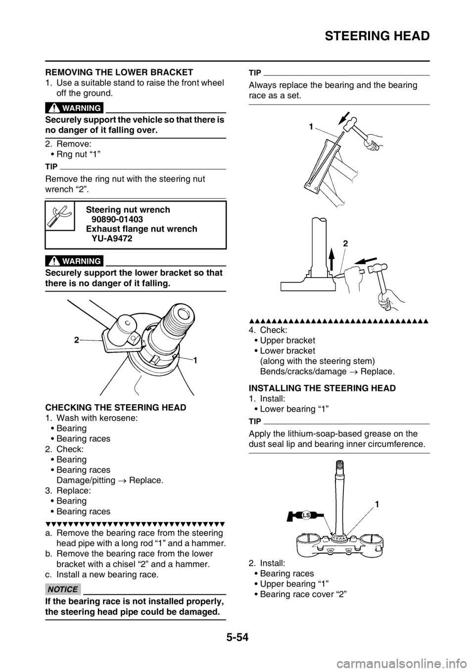
2. Remove:
• Rng nut “1”
TIP
Remove the ring nut with the steering nut
wrench “2”.
EWA
WARNING
Securely support the lower bracket so that
there is no danger of it falling.
EAS2GB2207CHECKING THE STEERING HEAD
1. Wash with kerosene:
• Bearing
• Bearing races
2. Check:
• Bearing
• Bearing races
Damage/pitting Replace.
3. Replace:
• Bearing
• Bearing races
▼▼▼▼▼▼▼▼▼▼▼▼▼▼▼▼▼▼▼▼▼▼▼▼▼▼▼▼▼▼▼▼
a. Remove the bearing race from the steering
head pipe with a long rod “1” and a hammer.
b. Remove the bearing race from the lower
bracket with a chisel “2” and a hammer.
c. Install a new bearing race.
ECA
NOTICE
If the bearing race is not installed properly,
the steering head pipe could be damaged.
TIP
Always replace the bearing and the bearing
race as a set.
▲▲▲▲▲▲▲▲▲▲▲▲▲▲▲▲▲▲▲▲▲▲▲▲▲▲▲▲▲▲▲▲
4. Check:
• Upper bracket
• Lower bracket
(along with the steering stem)
Bends/cracks/damage Replace.
EAS2GB2208INSTALLING THE STEERING HEAD
1. Install:
• Lower bearing “1”
TIP
Apply the lithium-soap-based grease on the
dust seal lip and bearing inner circumference.
2. Install:
• Bearing races
• Upper bearing “1”
• Bearing race cover “2” Steering nut wrench
90890-01403
Exhaust flange nut wrench
YU-A9472
Page 218 of 430
REAR SHOCK ABSORBER ASSEMBLY
5-60
EAS2GB2210HANDLING THE REAR SHOCK ABSORBEREWA
WARNING
This rear shock absorber contains highly
compressed nitrogen gas. Before handling
the rear shock absorber, read and make
sure that you understand the following in-
formation. The manufacturer cannot be held
responsible for property damage or person-
al injury that may result from improper han-
dling of the rear shock absorber.
• Do not tamper or attempt to open the rear
shock absorber.
• Do not subject the rear shock absorber to
an open flame or any other source of high
heat. High heat can cause an explosion
due to excessive gas pressure.
• Do not deform or damage the rear shock
absorber in any way. Rear shock absorber
damage will result in poor damping perfor-
mance.
TIP
A break-in is required up to about 50 km of run-
ning.
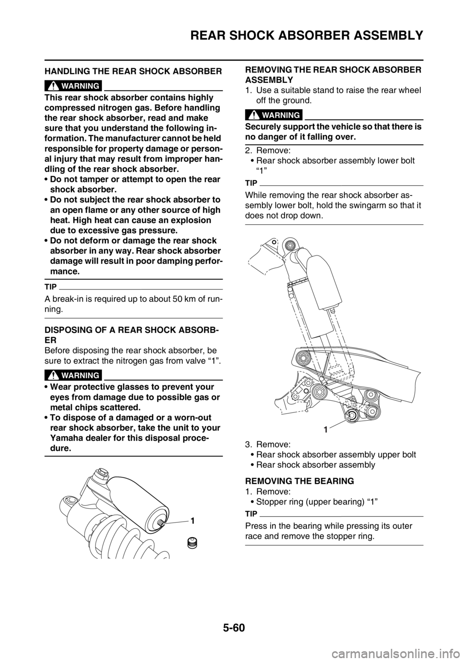
EAS2GB2211DISPOSING OF A REAR SHOCK ABSORB-
ER
Before disposing the rear shock absorber, be
sure to extract the nitrogen gas from valve “1”.
EWA
WARNING
• Wear protective glasses to prevent your
eyes from damage due to possible gas or
metal chips scattered.
• To dispose of a damaged or a worn-out
rear shock absorber, take the unit to your
Yamaha dealer for this disposal proce-
dure.
EAS2GB2212
REMOVING THE REAR SHOCK ABSORBER
ASSEMBLY
1. Use a suitable stand to raise the rear wheel
off the ground.
EWA
WARNING
Securely support the vehicle so that there is
no danger of it falling over.
2. Remove:
• Rear shock absorber assembly lower bolt
“1”
TIP
While removing the rear shock absorber as-
sembly lower bolt, hold the swingarm so that it
does not drop down.
3. Remove:
• Rear shock absorber assembly upper bolt
• Rear shock absorber assembly
EAS2GB2213REMOVING THE BEARING
1. Remove:
• Stopper ring (upper bearing) “1”
TIP
Press in the bearing while pressing its outer
race and remove the stopper ring.
1
1
Page 223 of 430
SWINGARM
5-65
EAS2GB2219REMOVING THE SWINGARM
1. Use a suitable stand to raise the rear wheel
off the ground.
EWA
WARNING
Securely support the vehicle so that there is
no danger of it falling over.
2. Measure:
• Swingarm side play
• Swingarm vertical movement
▼▼▼▼▼▼▼▼▼▼▼▼▼▼▼▼▼▼▼▼▼▼▼▼▼▼▼▼▼▼▼▼
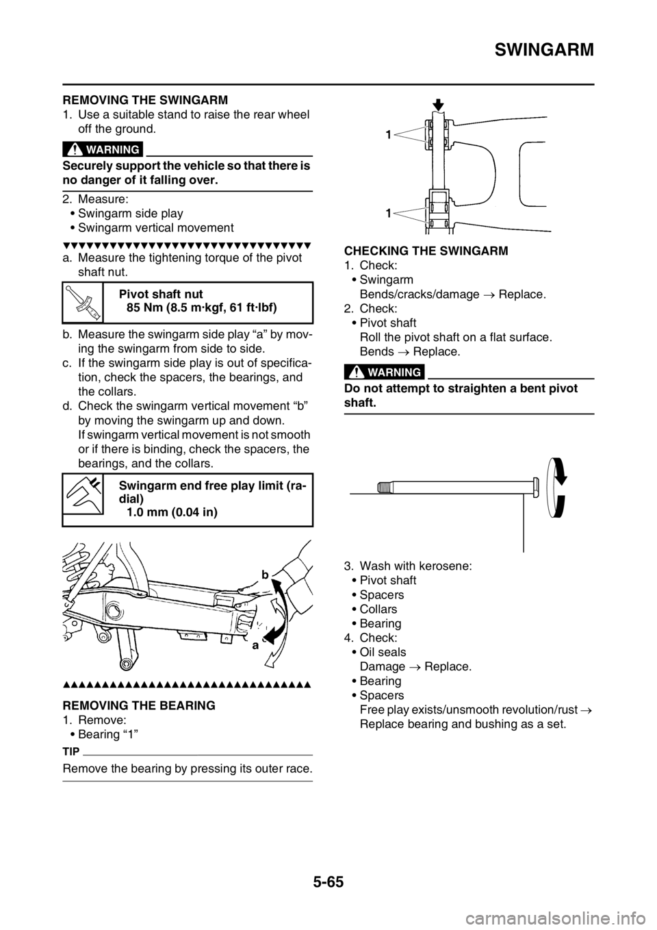
a. Measure the tightening torque of the pivot
shaft nut.
b. Measure the swingarm side play “a” by mov-
ing the swingarm from side to side.
c. If the swingarm side play is out of specifica-
tion, check the spacers, the bearings, and
the collars.
d. Check the swingarm vertical movement “b”
by moving the swingarm up and down.
If swingarm vertical movement is not smooth
or if there is binding, check the spacers, the
bearings, and the collars.
▲▲▲▲▲▲▲▲▲▲▲▲▲▲▲▲▲▲▲▲▲▲▲▲▲▲▲▲▲▲▲▲
EAS2GB2220REMOVING THE BEARING
1. Remove:
• Bearing “1”
TIP
Remove the bearing by pressing its outer race.
EAS2GB2221CHECKING THE SWINGARM
1. Check:
• Swingarm
Bends/cracks/damage Replace.
2. Check:
• Pivot shaft
Roll the pivot shaft on a flat surface.
Bends Replace.
EWA
WARNING
Do not attempt to straighten a bent pivot
shaft.
3. Wash with kerosene:
• Pivot shaft
• Spacers
•Collars
• Bearing
4. Check:
• Oil seals
Damage Replace.
• Bearing
• Spacers
Free play exists/unsmooth revolution/rust
Replace bearing and bushing as a set. Pivot shaft nut
85 Nm (8.5 m·kgf, 61 ft·lbf)
Swingarm end free play limit (ra-
dial)
1.0 mm (0.04 in)
T R..
Page 226 of 430
CHAIN DRIVE
5-68
EAS23420REMOVING THE DRIVE CHAIN
1. Stand the vehicle on a level surface.
EWA
WARNING
Securely support the vehicle so that there is
no danger of it falling over.
TIP
Place the vehicle on a suitable stand so that the
rear wheel is elevated.
2. Remove:
•Drive chain
TIP
Cut the drive chain with the drive chain cut &
rivet tool. (Use goods on the market)
EAS23441CHECKING THE DRIVE CHAIN
1. Measure:
• 15-link section of the drive chain
Out of specification Replace the drive
chain.
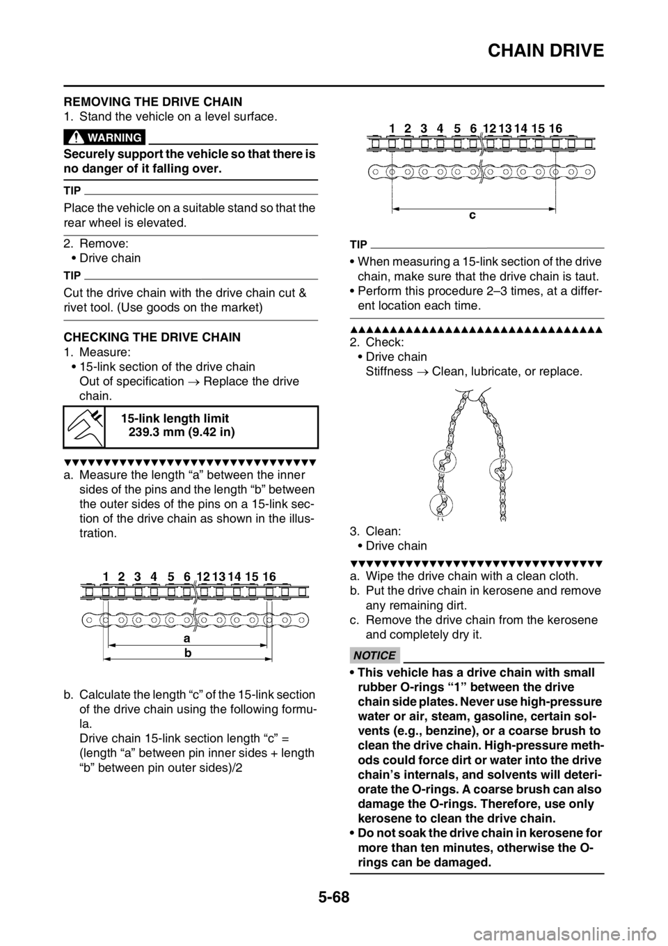
▼▼▼▼▼▼▼▼▼▼▼▼▼▼▼▼▼▼▼▼▼▼▼▼▼▼▼▼▼▼▼▼
a. Measure the length “a” between the inner
sides of the pins and the length “b” between
the outer sides of the pins on a 15-link sec-
tion of the drive chain as shown in the illus-
tration.
b. Calculate the length “c” of the 15-link section
of the drive chain using the following formu-
la.
Drive chain 15-link section length “c” =
(length “a” between pin inner sides + length
“b” between pin outer sides)/2
TIP
• When measuring a 15-link section of the drive
chain, make sure that the drive chain is taut.
• Perform this procedure 2–3 times, at a differ-
ent location each time.
▲▲▲▲▲▲▲▲▲▲▲▲▲▲▲▲▲▲▲▲▲▲▲▲▲▲▲▲▲▲▲▲
2. Check:
•Drive chain
Stiffness Clean, lubricate, or replace.
3. Clean:
•Drive chain
▼▼▼▼▼▼▼▼▼▼▼▼▼▼▼▼▼▼▼▼▼▼▼▼▼▼▼▼▼▼▼▼
a. Wipe the drive chain with a clean cloth.
b. Put the drive chain in kerosene and remove
any remaining dirt.
c. Remove the drive chain from the kerosene
and completely dry it.
ECA
NOTICE
• This vehicle has a drive chain with small
rubber O-rings “1” between the drive
chain side plates. Never use high-pressure
water or air, steam, gasoline, certain sol-
vents (e.g., benzine), or a coarse brush to
clean the drive chain. High-pressure meth-
ods could force dirt or water into the drive
chain’s internals, and solvents will deteri-
orate the O-rings. A coarse brush can also
damage the O-rings. Therefore, use only
kerosene to clean the drive chain.
• Do not soak the drive chain in kerosene for
more than ten minutes, otherwise the O-
rings can be damaged. 15-link length limit
239.3 mm (9.42 in)
Page 234 of 430
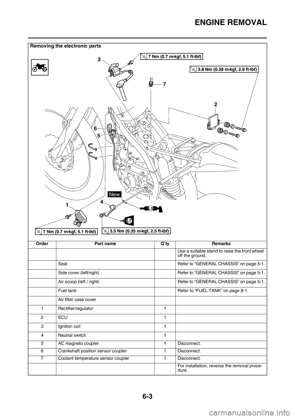
ENGINE REMOVAL
6-3
Removing the electronic parts
Order Part name Q’ty Remarks
Use a suitable stand to raise the front wheel
off the ground.
Seat Refer to “GENERAL CHASSIS” on page 5-1.
Side cover (left/right) Refer to “GENERAL CHASSIS” on page 5-1.
Air scoop (left / right) Refer to “GENERAL CHASSIS” on page 5-1.
Fuel tank Refer to “FUEL TANK” on page 8-1.
Air filter case cover
1 Rectifier/regulator 1
2ECU 1
3 Ignition coil 1
4 Neutral switch 1
5 AC magneto coupler 1 Disconnect.
6 Crankshaft position sensor coupler 1 Disconnect.
7 Coolant temperature sensor coupler 1 Disconnect.
For installation, reverse the removal proce-
dure.
T.R.
T.R.
T.R.T.R.
7 3
6
5
142
LT
New
LS
Page 325 of 430
FUEL TANK
8-4
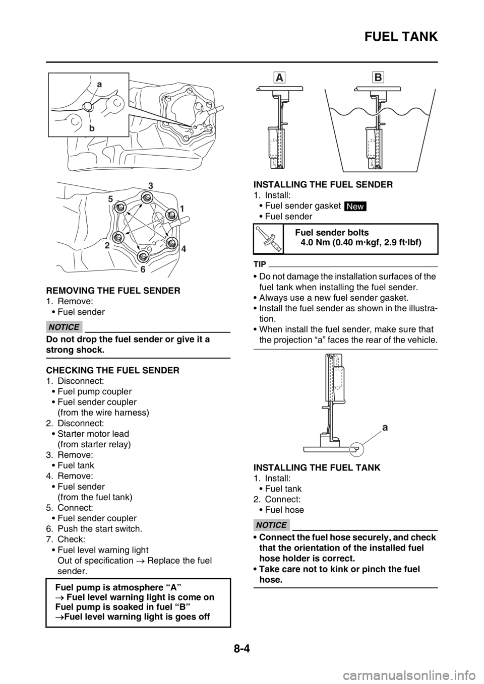
EAS2GB2346REMOVING THE FUEL SENDER
1. Remove:
• Fuel sender
ECA
NOTICE
Do not drop the fuel sender or give it a
strong shock.
EAS2GB2347CHECKING THE FUEL SENDER
1. Disconnect:
• Fuel pump coupler
• Fuel sender coupler
(from the wire harness)
2. Disconnect:
• Starter motor lead
(from starter relay)
3. Remove:
• Fuel tank
4. Remove:
• Fuel sender
(from the fuel tank)
5. Connect:
• Fuel sender coupler
6. Push the start switch.
7. Check:
• Fuel level warning light
Out of specification Replace the fuel
sender.
EAS2GB2348INSTALLING THE FUEL SENDER
1. Install:
• Fuel sender gasket
• Fuel sender
TIP
• Do not damage the installation surfaces of the
fuel tank when installing the fuel sender.
• Always use a new fuel sender gasket.
• Install the fuel sender as shown in the illustra-
tion.
• When install the fuel sender, make sure that
the projection “a” faces the rear of the vehicle.
EAS2GB2349INSTALLING THE FUEL TANK
1. Install:
• Fuel tank
2. Connect:
• Fuel hose
ECA
NOTICE
• Connect the fuel hose securely, and check
that the orientation of the installed fuel
hose holder is correct.
• Take care not to kink or pinch the fuel
hose.
Fuel pump is atmosphere “A”
Fuel level warning light is come on
Fuel pump is soaked in fuel “B”
Fuel level warning light is goes off
a
b
4 1
2
6
53
Fuel sender bolts
4.0 Nm (0.40 m·kgf, 2.9 ft·lbf)
AB
New
T R..
a