engine YAMAHA WR 400F 2000 Notices Demploi (in French)
[x] Cancel search | Manufacturer: YAMAHA, Model Year: 2000, Model line: WR 400F, Model: YAMAHA WR 400F 2000Pages: 654, PDF Size: 60.12 MB
Page 527 of 654
5 - 40
CHAS
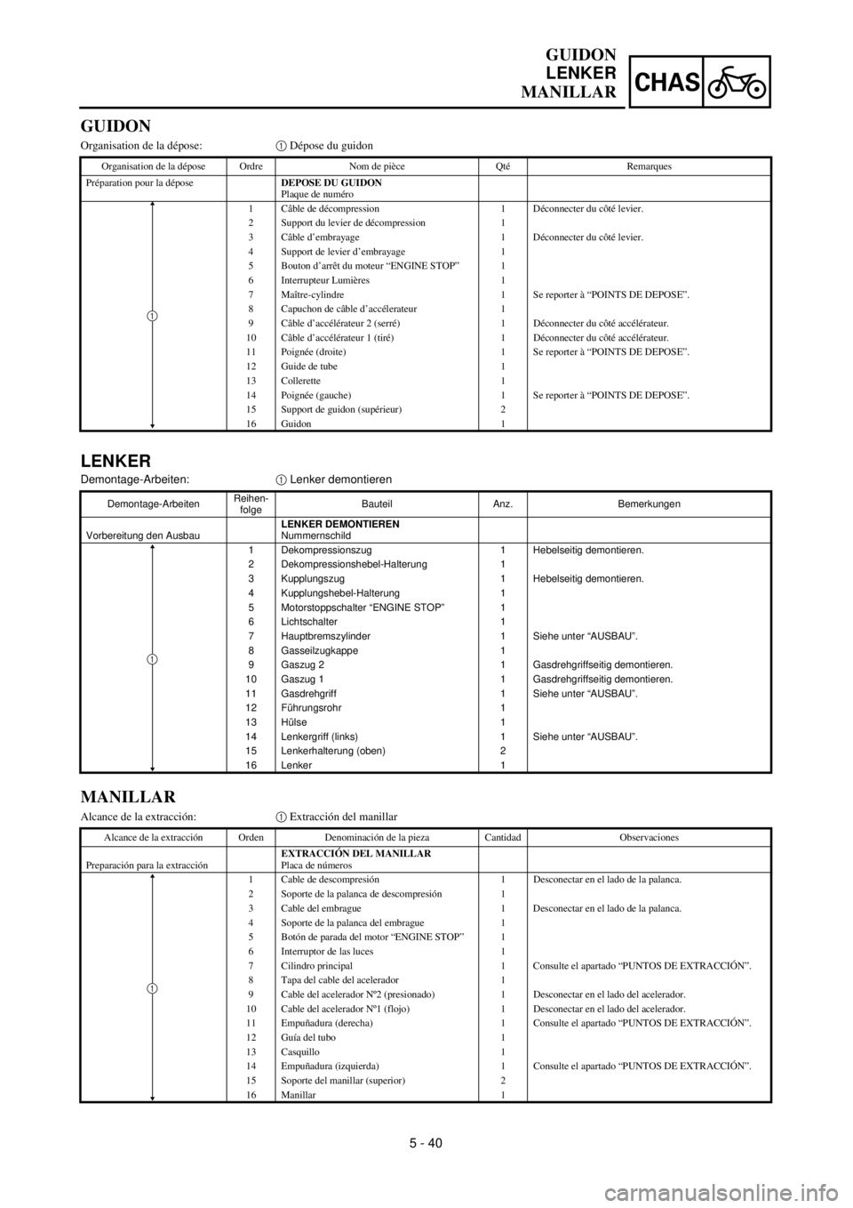
LENKER
Demontage-Arbeiten:1 Lenker demontieren
Demontage-ArbeitenReihen-
folgeBauteil Anz. Bemerkungen
Vorbereitung den AusbauLENKER DEMONTIEREN
Nummernschild
1 Dekompressionszug 1 Hebelseitig demontieren.
2 Dekompressionshebel-Halterung 1
3 Kupplungszug 1 Hebelseitig demontieren.
4 Kupplungshebel-Halterung 1
5 Motorstoppschalter “ENGINE STOP” 1
6 Lichtschalter 1
7 Hauptbremszylinder 1 Siehe unter “AUSBAU”.
8 Gasseilzugkappe 1
9 Gaszug 2 1 Gasdrehgriffseitig demontieren.
10 Gaszug 1 1 Gasdrehgriffseitig demontieren.
11 Gasdrehgriff 1 Siehe unter “AUSBAU”.
12 Führungsrohr 1
13 Hülse 1
14 Lenkergriff (links) 1 Siehe unter “AUSBAU”.
15 Lenkerhalterung (oben) 2
16Lenker
1
1
GUIDON
LENKER
MANILLAR
GUIDON
Organisation de la dépose:1 Dépose du guidon
Organisation de la dépose Ordre Nom de pièce Qté Remarques
Préparation pour la déposeDEPOSE DU GUIDON
Plaque de numéro
1 Câble de décompression 1 Déconnecter du côté levier.
2 Support du levier de décompression 1
3 Câble d’embrayage 1 Déconnecter du côté levier.
4 Support de levier d’embrayage 1
5 Bouton d’arrêt du moteur “ENGINE STOP” 1
6 Interrupteur Lumières 1
7 Maître-cylindre 1 Se reporter à “POINTS DE DEPOSE”.
8 Capuchon de câble d’accélerateur 1
9 Câble d’accélérateur 2 (serré) 1 Déconnecter du côté accélérateur.
10 Câble d’accélérateur 1 (tiré) 1 Déconnecter du côté accélérateur.
11 Poignée (droite) 1 Se reporter à “POINTS DE DEPOSE”.
12 Guide de tube 1
13 Collerette 1
14 Poignée (gauche) 1 Se reporter à “POINTS DE DEPOSE”.
15 Support de guidon (supérieur) 2
16 Guidon 1
1
MANILLAR
Alcance de la extracción:1 Extracción del manillar
Alcance de la extracción Orden Denominación de la pieza Cantidad Observaciones
Preparación para la extracciónEXTRACCIÓN DEL MANILLAR
Placa de números
1 Cable de descompresión 1 Desconectar en el lado de la palanca.
2 Soporte de la palanca de descompresión 1
3 Cable del embrague 1 Desconectar en el lado de la palanca.
4 Soporte de la palanca del embrague 1
5 Botón de parada del motor “ENGINE STOP” 1
6 Interruptor de las luces 1
7 Cilindro principal 1 Consulte el apartado “PUNTOS DE EXTRACCIÓN”.
8 Tapa del cable del acelerador 1
9 Cable del acelerador Nº2 (presionado) 1 Desconectar en el lado del acelerador.
10 Cable del acelerador Nº1 (flojo) 1 Desconectar en el lado del acelerador.
11 Empuñadura (derecha) 1 Consulte el apartado “PUNTOS DE EXTRACCIÓN”.
12 Guía del tubo 1
13 Casquillo 1
14 Empuñadura (izquierda) 1 Consulte el apartado “PUNTOS DE EXTRACCIÓN”.
15 Soporte del manillar (superior) 2
16Manillar
1
1
Page 532 of 654
5 - 43
CHASHANDLEBAR
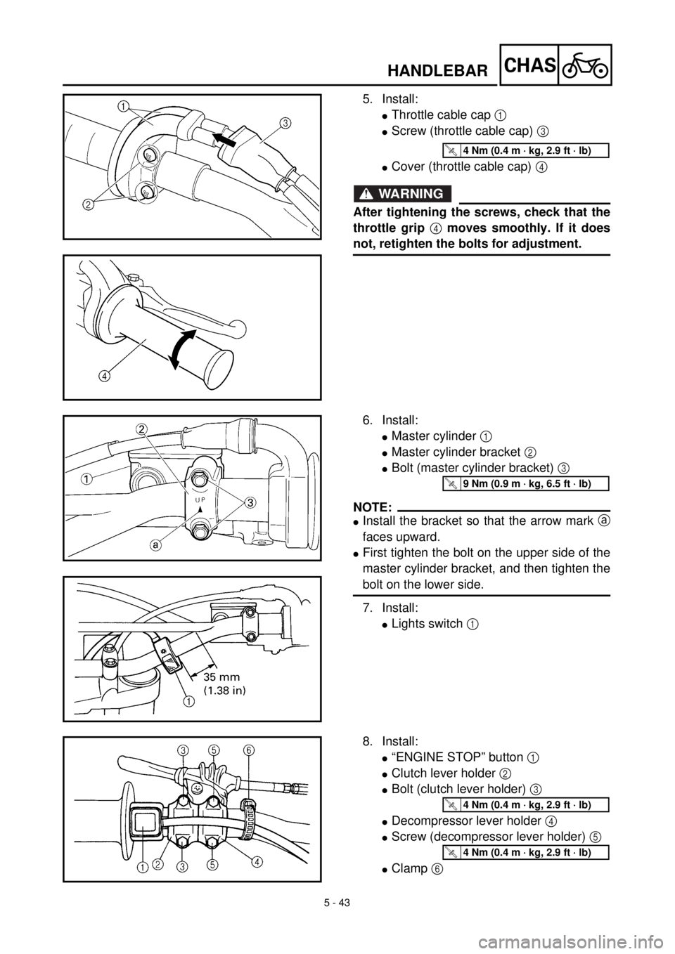
5. Install:
lThrottle cable cap 1
lScrew (throttle cable cap) 3
lCover (throttle cable cap) 4
WARNING
After tightening the screws, check that the
throttle grip 4 moves smoothly. If it does
not, retighten the bolts for adjustment.
T R..4 Nm (0.4 m · kg, 2.9 ft · lb)
6. Install:
lMaster cylinder 1
lMaster cylinder bracket 2
lBolt (master cylinder bracket) 3
NOTE:
lInstall the bracket so that the arrow mark a
faces upward.
lFirst tighten the bolt on the upper side of the
master cylinder bracket, and then tighten the
bolt on the lower side.
7. Install:
lLights switch 1
T R..9 Nm (0.9 m · kg, 6.5 ft · lb)
8. Install:
l“ENGINE STOP” button 1
lClutch lever holder 2
lBolt (clutch lever holder) 3
lDecompressor lever holder 4
lScrew (decompressor lever holder) 5
lClamp 6
T R..4 Nm (0.4 m · kg, 2.9 ft · lb)
T R..4 Nm (0.4 m · kg, 2.9 ft · lb)
Page 533 of 654
5 - 43
CHAS
GUIDON
LENKER
MANILLAR
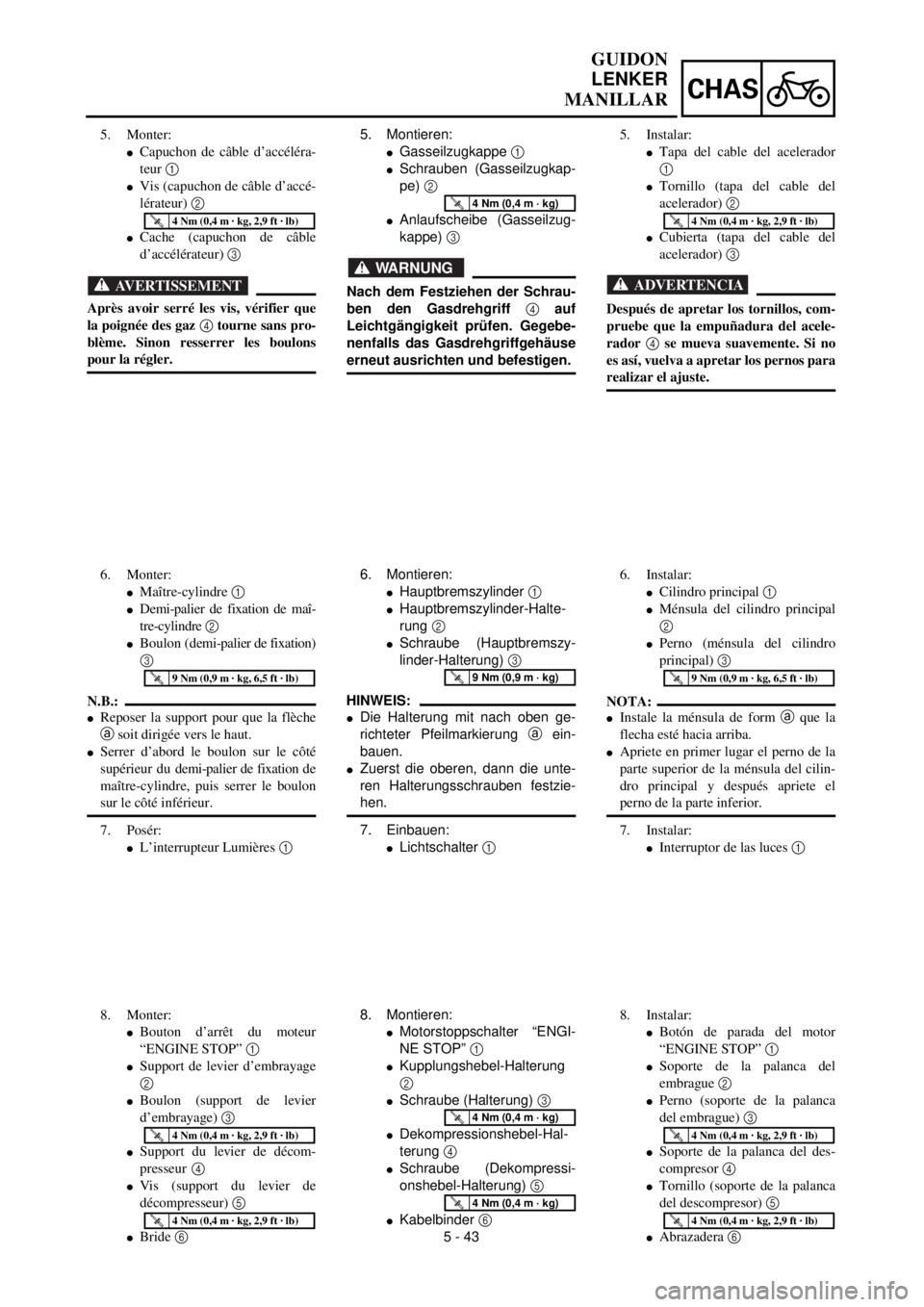
5. Montieren:
lGasseilzugkappe 1
lSchrauben (Gasseilzugkap-
pe) 2
lAnlaufscheibe (Gasseilzug-
kappe) 3
WARNUNG
Nach dem Festziehen der Schrau-
ben den Gasdrehgriff 4 auf
Leichtgängigkeit prüfen. Gegebe-
nenfalls das Gasdrehgriffgehäuse
erneut ausrichten und befestigen.
T R..4 Nm (0,4 m · kg)
6. Montieren:
lHauptbremszylinder 1
lHauptbremszylinder-Halte-
rung 2
lSchraube (Hauptbremszy-
linder-Halterung) 3
HINWEIS:
lDie Halterung mit nach oben ge-
richteter Pfeilmarkierung a ein-
bauen.
lZuerst die oberen, dann die unte-
ren Halterungsschrauben festzie-
hen.
7. Einbauen:
lLichtschalter 1
T R..9 Nm (0,9 m · kg)
8. Montieren:
lMotorstoppschalter “ENGI-
NE STOP” 1
lKupplungshebel-Halterung
2
lSchraube (Halterung) 3
lDekompressionshebel-Hal-
terung 4
lSchraube (Dekompressi-
onshebel-Halterung) 5
lKabelbinder 6
T R..4 Nm (0,4 m · kg)
T R..4 Nm (0,4 m · kg)
5. Monter:
lCapuchon de câble d’accéléra-
teur 1
lVis (capuchon de câble d’accé-
lérateur) 2
lCache (capuchon de câble
d’accélérateur) 3
AVERTISSEMENT
Après avoir serré les vis, vérifier que
la poignée des gaz 4 tourne sans pro-
blème. Sinon resserrer les boulons
pour la régler.
T R..4 Nm (0,4 m · kg, 2,9 ft · lb)
6. Monter:
lMaître-cylindre 1
lDemi-palier de fixation de maî-
tre-cylindre 2
lBoulon (demi-palier de fixation)
3
N.B.:
lReposer la support pour que la flèche
a soit dirigée vers le haut.
lSerrer d’abord le boulon sur le côté
supérieur du demi-palier de fixation de
maître-cylindre, puis serrer le boulon
sur le côté inférieur.
7. Posér:
lL’interrupteur Lumières 1
T R..9 Nm (0,9 m · kg, 6,5 ft · lb)
8. Monter:
lBouton d’arrêt du moteur
“ENGINE STOP” 1
lSupport de levier d’embrayage
2
lBoulon (support de levier
d’embrayage) 3
lSupport du levier de décom-
presseur
4
lVis (support du levier de
décompresseur) 5
lBride 6
T R..4 Nm (0,4 m · kg, 2,9 ft · lb)
T R..4 Nm (0,4 m · kg, 2,9 ft · lb)
5. Instalar:
lTapa del cable del acelerador
1
lTornillo (tapa del cable del
acelerador) 2
lCubierta (tapa del cable del
acelerador) 3
ADVERTENCIA
Después de apretar los tornillos, com-
pruebe que la empuñadura del acele-
rador 4 se mueva suavemente. Si no
es así, vuelva a apretar los pernos para
realizar el ajuste.
T R..4 Nm (0,4 m · kg, 2,9 ft · lb)
6. Instalar:
lCilindro principal 1
lMénsula del cilindro principal
2
lPerno (ménsula del cilindro
principal) 3
NOTA:
lInstale la ménsula de form a que la
flecha esté hacia arriba.
lApriete en primer lugar el perno de la
parte superior de la ménsula del cilin-
dro principal y después apriete el
perno de la parte inferior.
7. Instalar:
lInterruptor de las luces 1
T R..9 Nm (0,9 m · kg, 6,5 ft · lb)
8. Instalar:
lBotón de parada del motor
“ENGINE STOP” 1
lSoporte de la palanca del
embrague 2
lPerno (soporte de la palanca
del embrague) 3
lSoporte de la palanca del des-
compresor 4
lTornillo (soporte de la palanca
del descompresor) 5
lAbrazadera 6
T R..4 Nm (0,4 m · kg, 2,9 ft · lb)
T R..4 Nm (0,4 m · kg, 2,9 ft · lb)
Page 534 of 654
5 - 44
CHASHANDLEBAR
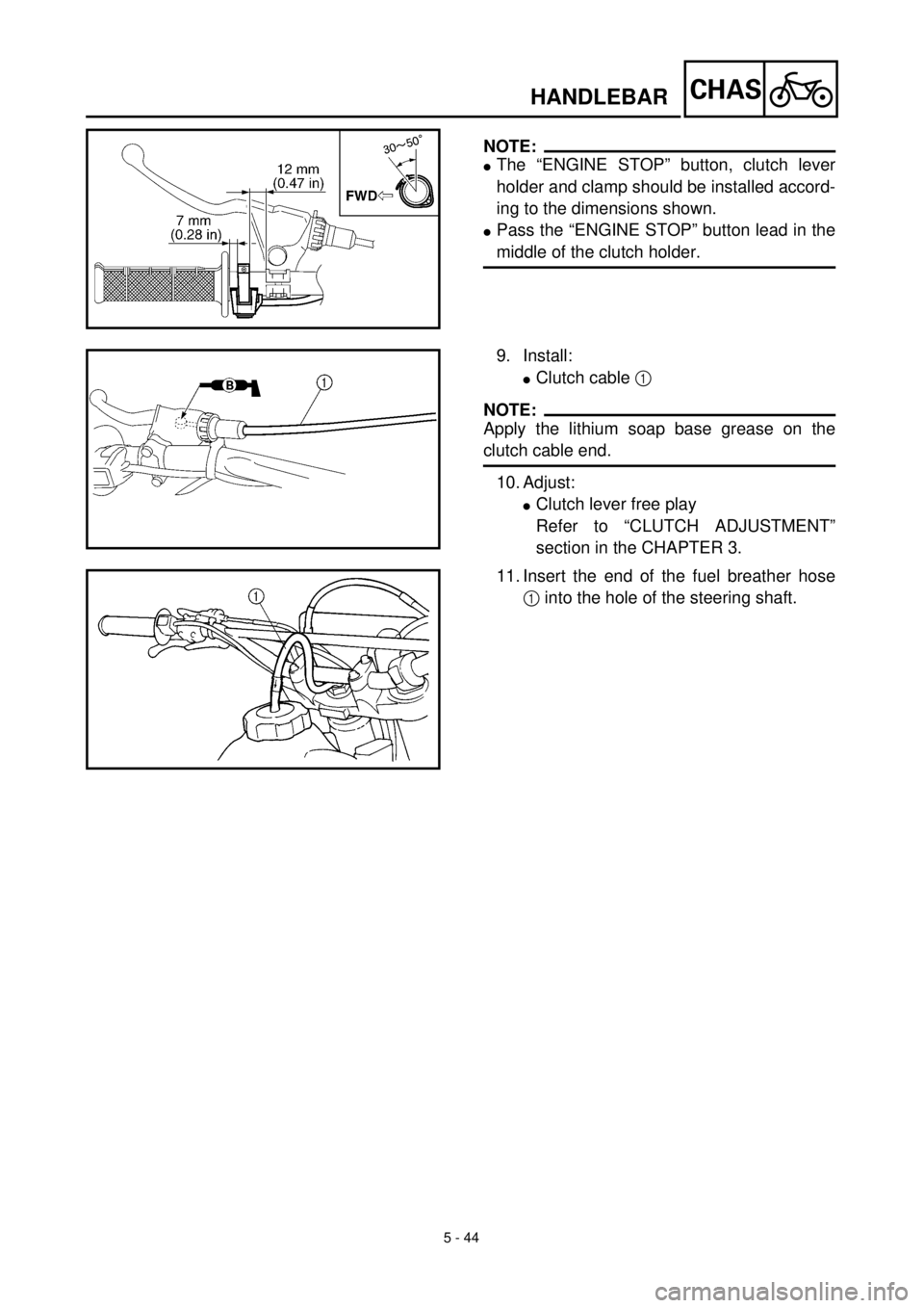
NOTE:
lThe “ENGINE STOP” button, clutch lever
holder and clamp should be installed accord-
ing to the dimensions shown.
lPass the “ENGINE STOP” button lead in the
middle of the clutch holder.
9. Install:
lClutch cable 1
NOTE:
Apply the lithium soap base grease on the
clutch cable end.
10. Adjust:
lClutch lever free play
Refer to “CLUTCH ADJUSTMENT”
section in the CHAPTER 3.
11. Insert the end of the fuel breather hose
1 into the hole of the steering shaft.
Page 535 of 654
5 - 44
CHAS
GUIDON
LENKER
MANILLAR
HINWEIS:
lMotorstoppschalter, Kupplungshe-
bel-Halterung und Kabelbinder laut
Abbildung montieren.
lDas Motorstoppschalter-Kabel mit-
tig durch die Kupplungshebel-Hal-
terung führen.
9. Montieren:
lKupplungszug 1
HINWEIS:
Lithiumfett auf das Kupplungszug-
Ende auftragen.
10. Einstellen:
lKupplungszugspiel
Siehe unter “KUPPLUNG
EINSTELLEN” im KAPITEL
3.
11. Das Kraftstofftank-
Entlüftungsschlauch-Ende 1
durch die Bohrung im Num-
mernschild führen.
N.B.:
lLe bouton d’arrêt du moteur
“ENGINE STOP”, le support et la
bride de levier d’embrayage doivent
être installés selon les dimensions
indiquées.
lFaire passer le fil de bouton d’arrêt du
moteur “ENGINE STOP” au centre du
support d’embrayage.
9. Monter:
lCâble d’embrayage 1
N.B.:
Appliquer de la graisse à base de savon
au lithium sur l’extrémité du câble
d’embrayage.
10. Régler:
lJeu du levier d’embrayage
Se reporter à la section
“REGLAGE DE
L’EMBRAYAGE” du CHAPI-
TRE 3.
11. Introduire l’extrémité du conduit
d’aération de carburant 1 dans
les trous de la plaque de numéro.
NOTA:
lEl botón de parada del motor
“ENGINE STOP”, el soporte de la
palanca del embrague y la abrazadera
deben instalarse de acuerdo con las
dimensiones que aparecen.
lPase el cable del botón de parada del
motor “ENGINE STOP” por el medio
del soporte del embrague.
9. Instalar:
lCable del embrague 1
NOTA:
Aplique grasa con base de jabón de litio
en el extremo del cable del embrague.
10. Ajustar:
lJuego libre d e la palanca del
embrague
Consulte el apartado “AJUSTE
DEL EMBRAGUE” del CAPÍ-
TULO 3.
11. Inserte el extremo del tubo respi-
radero del combustible 1 en el
orificio del eje de dirección.
Page 536 of 654
5 - 45
CHAS
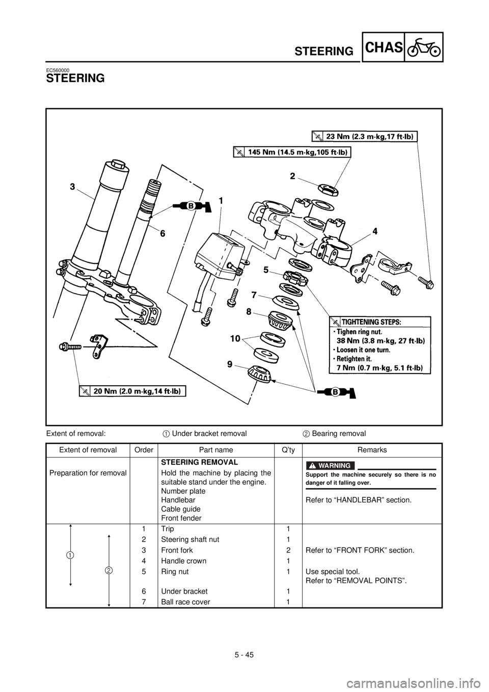
EC560000
STEERING
Extent of removal:1 Under bracket removal2 Bearing removal
Extent of removal Order Part name Q’ty Remarks
STEERING REMOVAL
Refer to “HANDLEBAR” section. Preparation for removal Hold the machine by placing the
suitable stand under the engine.
Number plate
Handlebar
Cable guide
Front fender
1 Trip 1
2 Steering shaft nut 1
3 Front fork 2 Refer to “FRONT FORK” section.
4 Handle crown 1
5 Ring nut 1 Use special tool.
Refer to “REMOVAL POINTS”.
6 Under bracket 1
7Ball race cover
1
WARNING
Support the machine securely so there is nodanger of it falling over.
2
1
STEERING
Page 548 of 654

5 - 51
CHASSWINGARM
EC570000
SWINGARM
Extent of removal:1 Swingarm removal
Extent of removal Order Part name Q’ty Remarks
STEERING REMOVAL
Refer to “FRONT BRAKE AND REAR
BRAKE” section.
Shift the brake pedal backward. Preparation for removal Hold the machine by placing the
suitable stand under the engine.
Brake hose holder
Rear caliper
Bolt (brake pedal)
Drive chain
1 Chain support 1
2 Chain tensioner (lower) 1
3 Bolt (rear shock absorber-relay
arm)1 Hold the swingarm.
4 Bolt (connecting rod) 1
5 Pivot shaft 1
6Swingarm
1
WARNING
Support the machine securely so there is nodanger of it falling over.
1
Page 562 of 654

5 - 58
CHASREAR SHOCK ABSORBER
EC580000
REAR SHOCK ABSORBER
Extent of removal:1 Rear shock absorber removal2 Rear shock absorber disassembly
Extent of removal Order Part name Q’ty Remarks
Preparation for removalREAR SHOCK ABSORBER
REMOVAL
Hold the machine by placing the
suitable stand under the engine.
Seat, fitting band and side covers Refer to “SEAT, FUEL TANK AND SIDE
COVERS” section in the CHAPTER 4.
Silencer Refer to “EXHAUST PIPE AND
SILENCER” section in the CHAPTER 4.
Drain the coolant. Refer to “COOLANT REPLACENENTR ”
section in the CHAPTER 3.
Coolant reservoir Refer to “RADIATOR” section in the
CHAPTER 4.
1 Tail light connector 2
2 Band 2
3 Bolt (brake reservoir tank) 1
4 Clamp (air cleaner joint) 1 Only loosening.
5 Rear frame 1
6 Bolt (rear shock absorber-relay arm) 1Hold the swingarm.
7 Bolt (rear shock absorber-frame) 1
8 Rear shock absorber 1
WARNING
Support the machine securely so there is nodanger of it falling over.
1
2
Page 574 of 654

6 - 1
–+ELEC
ELECTRICAL COMPONENTS AND WIRING DIAGRAM
EC600000
ELECTRICAL
EC610000
ELECTRICAL COMPONENTS AND WIRING DIAGRAM
EC611000
ELECTRICAL COMPONENTS
1
Headlight
2
“ENGINE STOP” button
3
Regulator
4
TPS (throttle position sensor)
5
Tail light
6
CDI magneto
7
Neutral switch
8
Ignition coil
9
Spark plug
0
Lights switch
A
CDI unit
COLOR CODE
B...................... Black
Br .................... Brown
G ..................... Green
Gy ................... Gray
L ...................... Blue
O ..................... Orange
P...................... Pink
R ..................... Red
EC612000
WIRING DIAGRAM
Sb .................... Sky blue
W ..................... White
Y ...................... Yellow
B/L ................... Black/Blue
B/W .................. Black/White
L/W .................. Blue/White
R/W .................. Red/White
6
B/L
R/WL/W
LY
L
Y
B
1B L
L YBLB YL BY
BYYLB
5LB
BYBL
LB
3
7
4 8
9
W
R Br
G P
BP
B Br
G W
R
O
L B
Y Sb
B/LSb
B/L B
Y O
L
A
2
Y
Br
B/WBB/WB
PGR
WB
L YL Y
B B/L
SbSbW
Sb
WL/W
R/WL/W
R/WSb
W2
N
13
4
5
O
B
0
6
B/WGyB/WGy
Page 575 of 654
–+ELEC
COMPOSANTS ELECTRIQUES ET SCHEMA DE CABLAGE
ELEKTRISCHE BAUTEILE UND SCHALTPLAN
COMPONENTES DEL SISTEMA ELÉCTRICO Y DIAGRAMA DE CABLES
ELEKTRISCHE ANLA-
GE
ELEKTRISCHE BAUTEI-
LE UND SCHALTPLAN
ELEKTRISCHE BAUTEILE
1
Scheinwerfer
2
Motorstoppschalter “ENGINE STOP”
3
Regler
4
Drosselklappensensor
5
Rücklicht
6
CDI-Schwungradmagnetzünder
7
Leerlaufschalter
8
Zündspule
9
Zündkerze
0
Lichtschalter
A
CDI-Zündbox
FARB-KODIERUNG
B ............................ schwarz
Br ........................... braun
G ............................ grün
Gy .......................... gran
L ............................. blau
O ............................ orange
P ............................ rosa
R ............................ rot
Sb .......................... hellblau
W ........................... weiß
Y ............................ gelb
B/L ......................... schwarz/blau
B/W ........................ schwarz/weiß
L/W ........................ blau/weiß
R/W ........................ rot/weiß
SCHALTPLAN
PARTIE ELECTRI-
QUE
COMPOSANTS ELECTRI-
QUES ET SCHEMA DE
CABLAGE
COMPOSANTS ELECTRIQUES
1
Phare
2
Bouton d’arrêt du moteur “ENGINE
STOP”
3
Régulateur
4
TPS (détecteur de position d’accélérateur)
5
Lampe arrière
6
Magnéto CDI
7
Contacteur de point mort
8
Bobine d’allumage
9
Bougie
0
Interrupteur lumières
A
Bloc CDI
CODE DE COULEUR
B ............................... Noir
Br .............................. Brun
G ............................... Vert
Gy ............................. Gris
L ................................ Bleu
O ............................... Orange
P ................................ Rose
R ............................... Rouge
Sb .............................. Bleu ciel
W .............................. Blanc
Y ............................... Jaune
B/L ............................ Noir/Bleu
B/W........................... Noir/Blanc
L/W ........................... Bleu/Blanc
R/W........................... Rouge/Blanc
SCHEMA DE CABLAGE
6 - 1
6
SISTEMA ELÉCTRI-
CO
COMPONENTES DEL SIS-
TEMA ELÉCTRICO Y
DIAGRAMA DE CABLES
COMPONENTES DEL SISTEMA
ELÉCTRICO
1
Faro
2
Botón de parada del motor “ENGINE
STOP”
3
Regulador
4
TPS (sensor de posición del acelerador)
5
Luz posterior
6
Magneto CDI
7
Interruptor de punto muerto
8
Bobina de encendido
9
Bujía
0
Interruptor de las luces
A
Unidad CDI
CÓDIGO DE COLOR
B ................................Negro
Br ...............................Marrón
G ................................Verde
Gy ..............................Gris
L ................................Azul
O ................................Naranja
P.................................Rosa
R ................................Rojo
Sb...............................Azul cielo
W ...............................Blanco
Y ................................Amarillo
B/L.............................Negro/Azul
B/W ...........................Negro/Blanco
L/W............................Azul/Blanco
R/W ...........................Rojo/Blanco
DIAGRAMA DE CABLES