engine YAMAHA WR 400F 2000 Notices Demploi (in French)
[x] Cancel search | Manufacturer: YAMAHA, Model Year: 2000, Model line: WR 400F, Model: YAMAHA WR 400F 2000Pages: 654, PDF Size: 60.12 MB
Page 212 of 654
3 - 24
INSP
ADJ
SPARK ARRESTER CLEANING (For USA)
WARNING
lBe sure the exhaust pipe and muffler are
cool before cleaning the spark arrester.
lDo not start the engine when cleaning the
exhaust system.
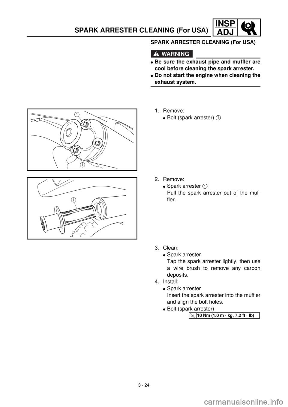
1. Remove:
lBolt (spark arrester) 1 1
1
2. Remove:
lSpark arrester 1
Pull the spark arrester out of the muf-
fler.
1
3. Clean:
lSpark arrester
Tap the spark arrester lightly, then use
a wire brush to remove any carbon
deposits.
4. Install:
lSpark arrester
Insert the spark arrester into the muffler
and align the bolt holes.
lBolt (spark arrester)
T R..10 Nm (1.0 m · kg, 7.2 ft · lb)
SPARK ARRESTER CLEANING (For USA)
Page 230 of 654
3 - 33
INSP
ADJ
DRIVE CHAIN SLACK ADJUSTMENT
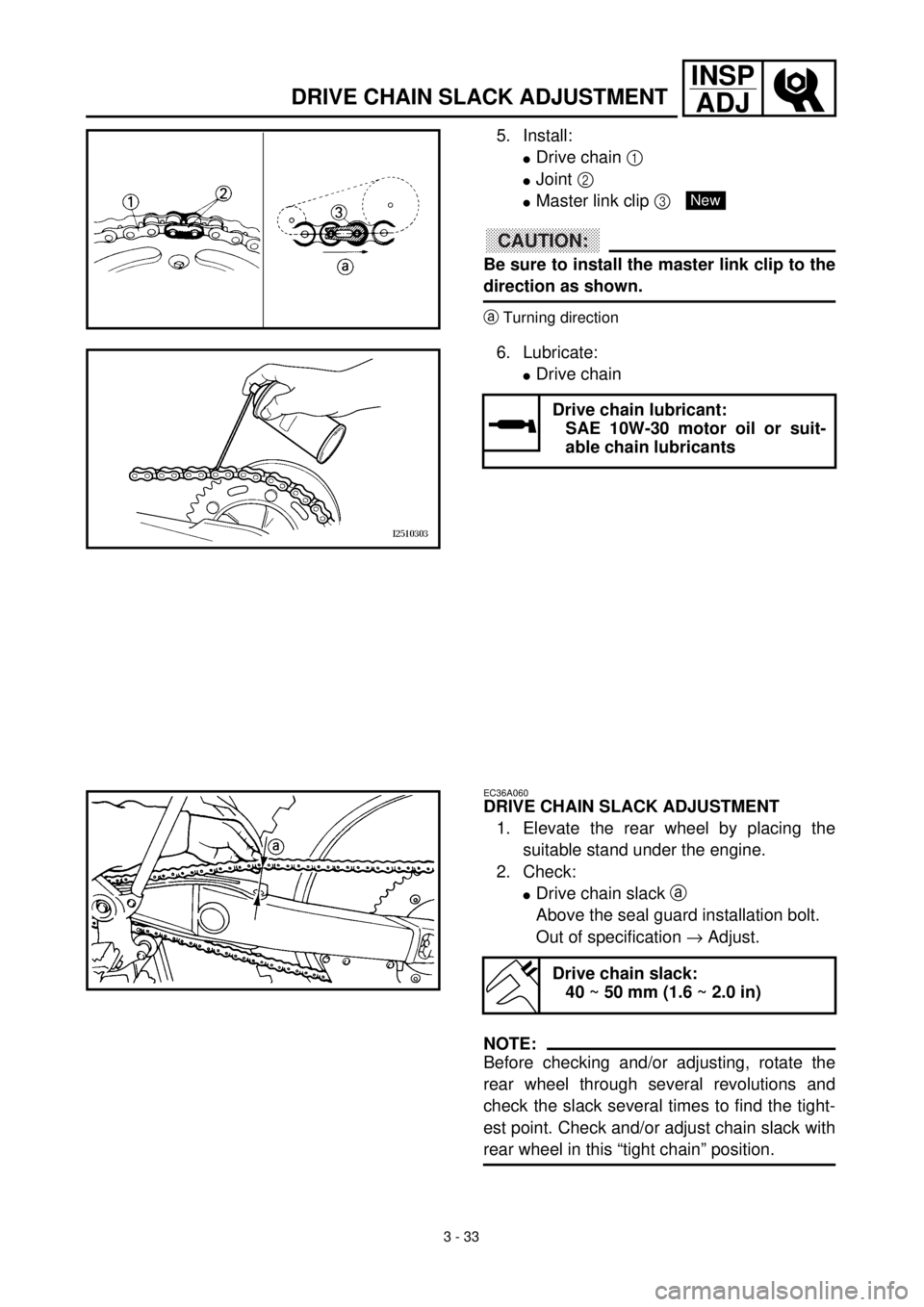
5. Install:
lDrive chain 1
lJoint 2
lMaster link clip 3
CAUTION:
Be sure to install the master link clip to the
direction as shown.
aTurning direction
6. Lubricate:
lDrive chain
Drive chain lubricant:
SAE 10W-30 motor oil or suit-
able chain lubricants
New
EC36A060
DRIVE CHAIN SLACK ADJUSTMENT
1. Elevate the rear wheel by placing the
suitable stand under the engine.
2. Check:
lDrive chain slack a
Above the seal guard installation bolt.
Out of specification ® Adjust.
NOTE:
Before checking and/or adjusting, rotate the
rear wheel through several revolutions and
check the slack several times to find the tight-
est point. Check and/or adjust chain slack with
rear wheel in this “tight chain” position.
Drive chain slack:
40 ~ 50 mm (1.6 ~ 2.0 in)
Page 232 of 654
3 - 34
INSP
ADJ
FRONT FORK INSPECTION
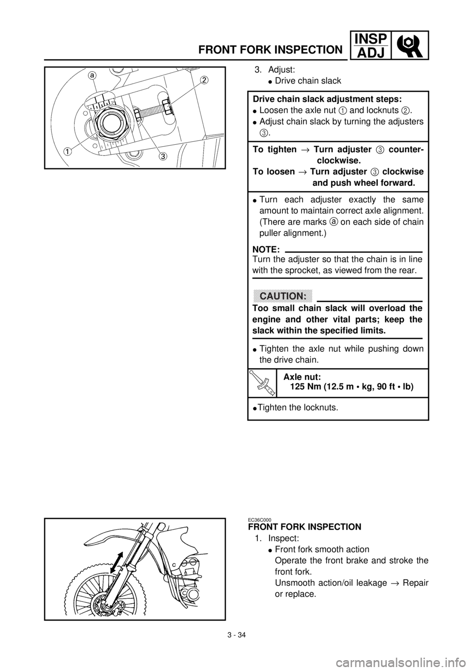
3. Adjust:
lDrive chain slack
Drive chain slack adjustment steps:
lLoosen the axle nut 1 and locknuts 2.
lAdjust chain slack by turning the adjusters
3.
To tighten ® Turn adjuster 3 counter-
clockwise.
To loosen ® Turn adjuster 3 clockwise
and push wheel forward.
lTurn each adjuster exactly the same
amount to maintain correct axle alignment.
(There are marks a on each side of chain
puller alignment.)
lTighten the axle nut while pushing down
the drive chain.
T R..
Axle nut:
125 Nm (12.5 m • kg, 90 ft • lb)
lTighten the locknuts.
NOTE:
Turn the adjuster so that the chain is in line
with the sprocket, as viewed from the rear.
CAUTION:
Too small chain slack will overload the
engine and other vital parts; keep the
slack within the specified limits.
EC36C000
FRONT FORK INSPECTION
1. Inspect:
lFront fork smooth action
Operate the front brake and stroke the
front fork.
Unsmooth action/oil leakage ® Repair
or replace.
Page 240 of 654
3 - 38
INSP
ADJREAR SHOCK ABSORBER SPRING PRELOAD
ADJUSTMENT
EC36M012
REAR SHOCK ABSORBER SPRING
PRELOAD ADJUSTMENT
1. Elevate the rear wheel by placing the
suitable stand under the engine.
2. Remove:
lRear frame
3. Loosen:
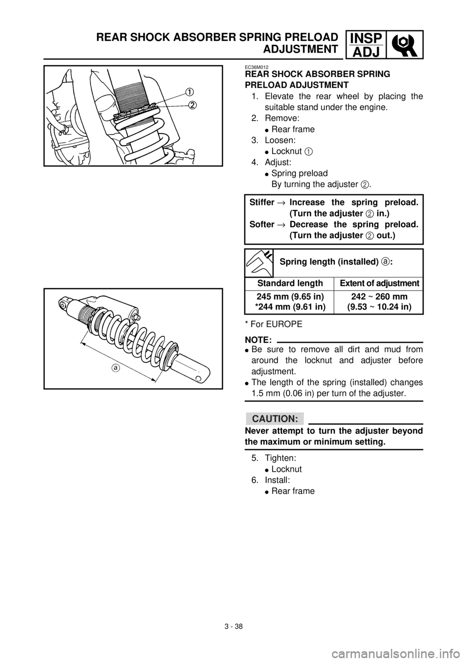
lLocknut 1
4. Adjust:
lSpring preload
By turning the adjuster 2.
* For EUROPE
NOTE:
lBe sure to remove all dirt and mud from
around the locknut and adjuster before
adjustment.
lThe length of the spring (installed) changes
1.5 mm (0.06 in) per turn of the adjuster.
CAUTION:
Never attempt to turn the adjuster beyond
the maximum or minimum setting.
5. Tighten:
lLocknut
6. Install:
lRear frame Stiffer ®Increase the spring preload.
(Turn the adjuster 2 in.)
Softer ®Decrease the spring preload.
(Turn the adjuster 2 out.)
Spring length (installed) a:
Standard lengthExtent of adjustment
245 mm (9.65 in)
*244 mm (9.61 in)242 ~ 260 mm
(9.53 ~ 10.24 in)
Page 250 of 654
3 - 43
INSP
ADJ
STEERING HEAD INSPECTION AND ADJUSTMENT
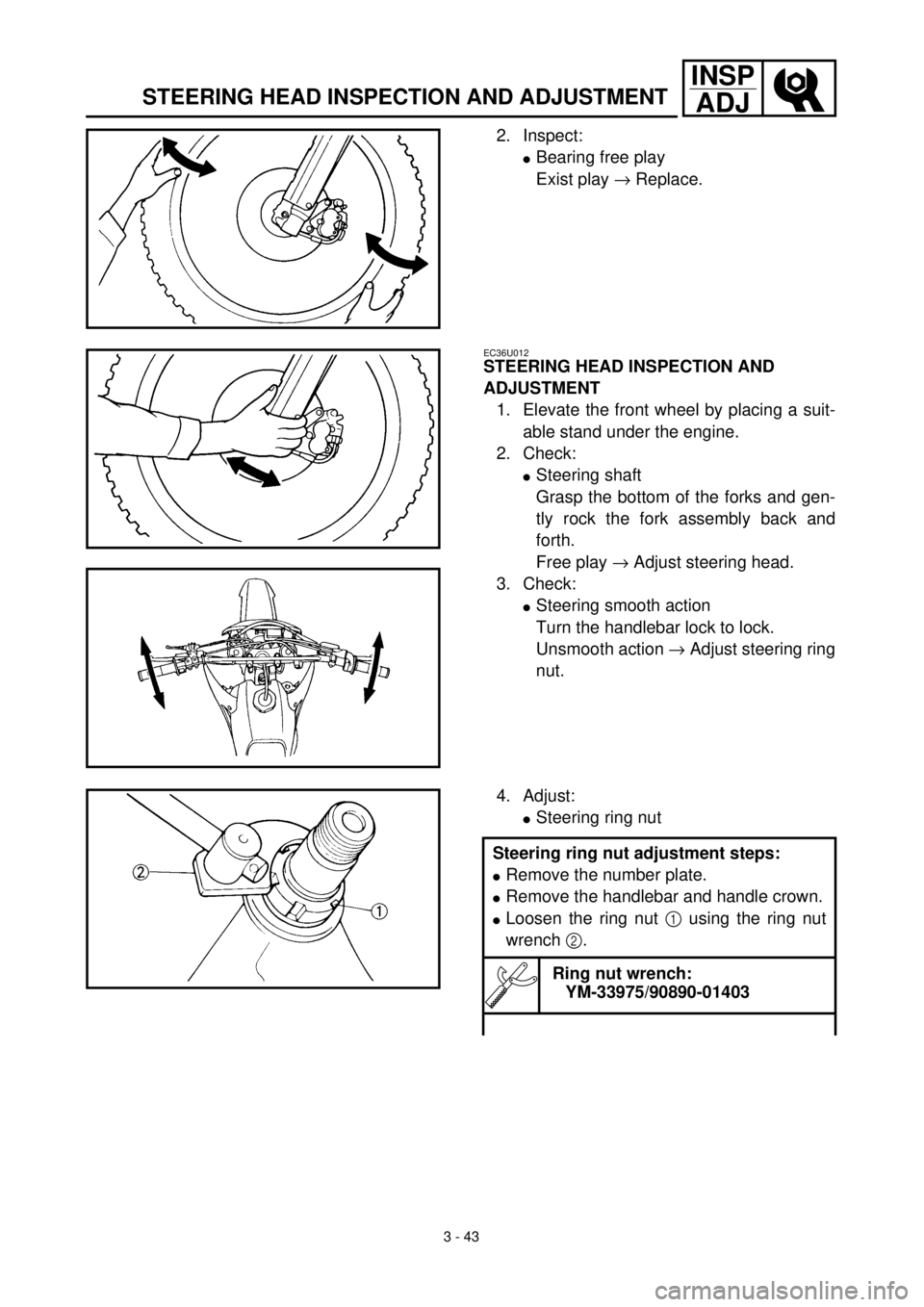
2. Inspect:
lBearing free play
Exist play ® Replace.
EC36U012
STEERING HEAD INSPECTION AND
ADJUSTMENT
1. Elevate the front wheel by placing a suit-
able stand under the engine.
2. Check:
lSteering shaft
Grasp the bottom of the forks and gen-
tly rock the fork assembly back and
forth.
Free play ® Adjust steering head.
3. Check:
lSteering smooth action
Turn the handlebar lock to lock.
Unsmooth action ® Adjust steering ring
nut.
4. Adjust:
lSteering ring nut
Steering ring nut adjustment steps:
lRemove the number plate.
lRemove the handlebar and handle crown.
lLoosen the ring nut 1 using the ring nut
wrench 2.
Ring nut wrench:
YM-33975/90890-01403
Page 256 of 654
3 - 46
INSP
ADJ
ELECTRICAL/SPARK PLUG INSPECTION
EC370000
ELECTRICAL
EC371001
SPARK PLUG INSPECTION
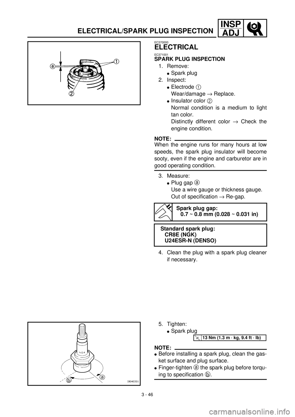
1. Remove:
lSpark plug
2. Inspect:
lElectrode 1
Wear/damage ® Replace.
lInsulator color 2
Normal condition is a medium to light
tan color.
Distinctly different color ® Check the
engine condition.
NOTE:
When the engine runs for many hours at low
speeds, the spark plug insulator will become
sooty, even if the engine and carburetor are in
good operating condition.
3. Measure:
lPlug gap a
Use a wire gauge or thickness gauge.
Out of specification ® Re-gap.
4. Clean the plug with a spark plug cleaner
if necessary.
Spark plug gap:
0.7 ~ 0.8 mm (0.028 ~ 0.031 in)
Standard spark plug:
CR8E (NGK)
U24ESR-N (DENSO)
5. Tighten:
lSpark plug
NOTE:
lBefore installing a spark plug, clean the gas-
ket surface and plug surface.
lFinger-tighten a the spark plug before torqu-
ing to specification b.
T R..13 Nm (1.3 m · kg, 9.4 ft · lb)
Page 258 of 654
3 - 47
INSP
ADJ
IGNITION TIMING CHECK
IGNITION TIMING CHECK
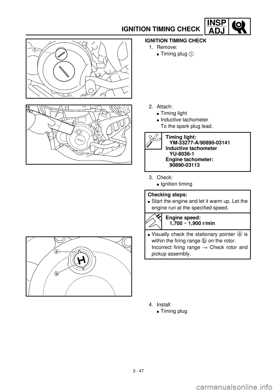
1. Remove:
lTiming plug 1
2. Attach:
lTiming light
lInductive tachometer
To the spark plug lead.
3. Check:
lIgnition timing
Timing light:
YM-33277-A/90890-03141
Inductive tachometer
YU-8036-1
Engine tachometer:
90890-03113
Checking steps:
lStart the engine and let it warm up. Let the
engine run at the specified speed.
Engine speed:
1,700 ~ 1,900 r/min
lVisually check the stationary pointer a is
within the firing range b on the rotor.
Incorrect firing range ® Check rotor and
pickup assembly.
4. Install:
lTiming plug
Page 264 of 654
ENG
4 - 1
3EC400000
ENGINE
EC4R0000
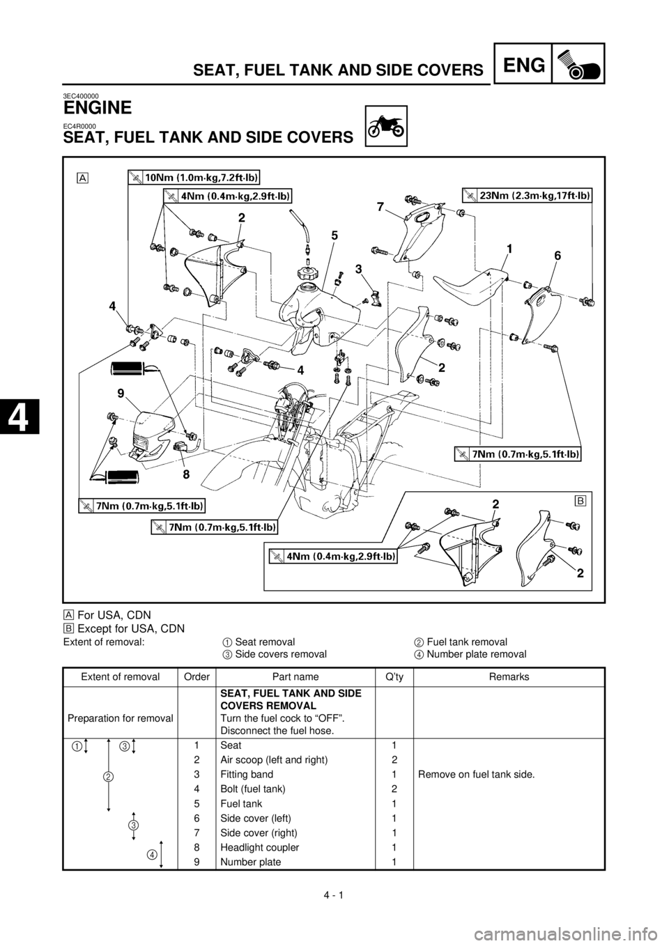
SEAT, FUEL TANK AND SIDE COVERS
SEAT, FUEL TANK AND SIDE COVERS
For USA, CDN
õ
Except for USA, CDN
Extent of removal:
1
Seat removal
2
Fuel tank removal
3
Side covers removal
4
Number plate removal
Extent of removal Order Part name Q’ty Remarks
Preparation for removal
SEAT, FUEL TANK AND SIDE
COVERS REMOVAL
Turn the fuel cock to “OFF”.
Disconnect the fuel hose.
1 Seat 1
2 Air scoop (left and right) 2
3 Fitting band 1 Remove on fuel tank side.
4 Bolt (fuel tank) 2
5 Fuel tank 1
6 Side cover (left) 1
7 Side cover (right) 1
8 Headlight coupler 1
9 Number plate 1
13
4
2
3
4
Page 268 of 654
ENG
4 - 3
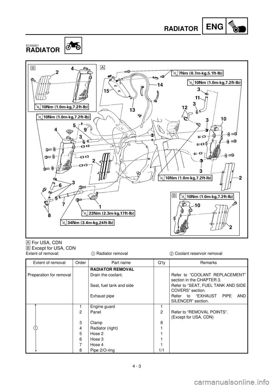
RADIATOR
EC450001
RADIATOR
For USA, CDN
õ
Except for USA, CDN
Extent of removal:
1
Radiator removal
2
Coolant reservoir removal
Extent of removal Order Part name Q’ty Remarks
RADIATOR REMOVAL
Preparation for removal Drain the coolant. Refer to “COOLANT REPLACEMENT”
section in the CHAPTER 3.
Seat, fuel tank and side Refer to “SEAT, FUEL TANK AND SIDE
COVERS” section.
Exhaust pipe Refer to “EXHAUST PIPE AND
SILENCER” section.
1 Engine guard 1
2 Panel 2 Refer to “REMOVAL POINTS”.
(Except for USA, CDN)
3 Clamp 8
4 Radiator (right) 1
5 Hose 2 1
6 Hose 3 1
7 Hose 4 1
8 Pipe 2/O-ring 1/1
1
Page 272 of 654
4 - 5
ENG
RADIATOR
EC456000
HANDLING NOTE
WARNING
Do not remove the radiator cap when the
engine and radiator are hot. Scalding hot
fluid and steam may be blown out under
pressure, which could cause serious
injury.
When the engine has cooled, open the radi-
ator cap by the following procedure:
Place a thick rag, like a towel, over the radi-
ator cap, slowly rotate the cap counter-
clockwise to the detent. This procedure
allows any residual pressure to escape.
When the hissing sound has stopped,
press down on the cap while turning coun-
terclockwise and remove it.
EC453000
REMOVAL POINTS
EC453200
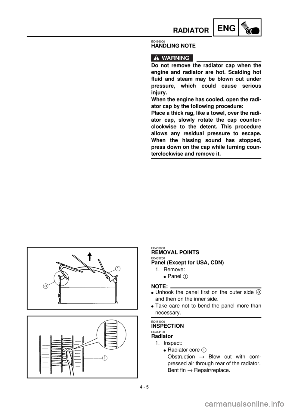
Panel (Except for USA, CDN)
1. Remove:
l
Panel
1
NOTE:
l
Unhook the panel first on the outer side
a
and then on the inner side.
l
Take care not to bend the panel more than
necessary.
EC454000
INSPECTION
EC444100
Radiator
1. Inspect:
l
Radiator core
1
Obstruction
®
Blow out with com-
pressed air through rear of the radiator.
Bent fin
®
Repair/replace.