lock YAMAHA WR 450F 2016 Owners Manual
[x] Cancel search | Manufacturer: YAMAHA, Model Year: 2016, Model line: WR 450F, Model: YAMAHA WR 450F 2016Pages: 426, PDF Size: 10.86 MB
Page 9 of 426
EAS2GC1007
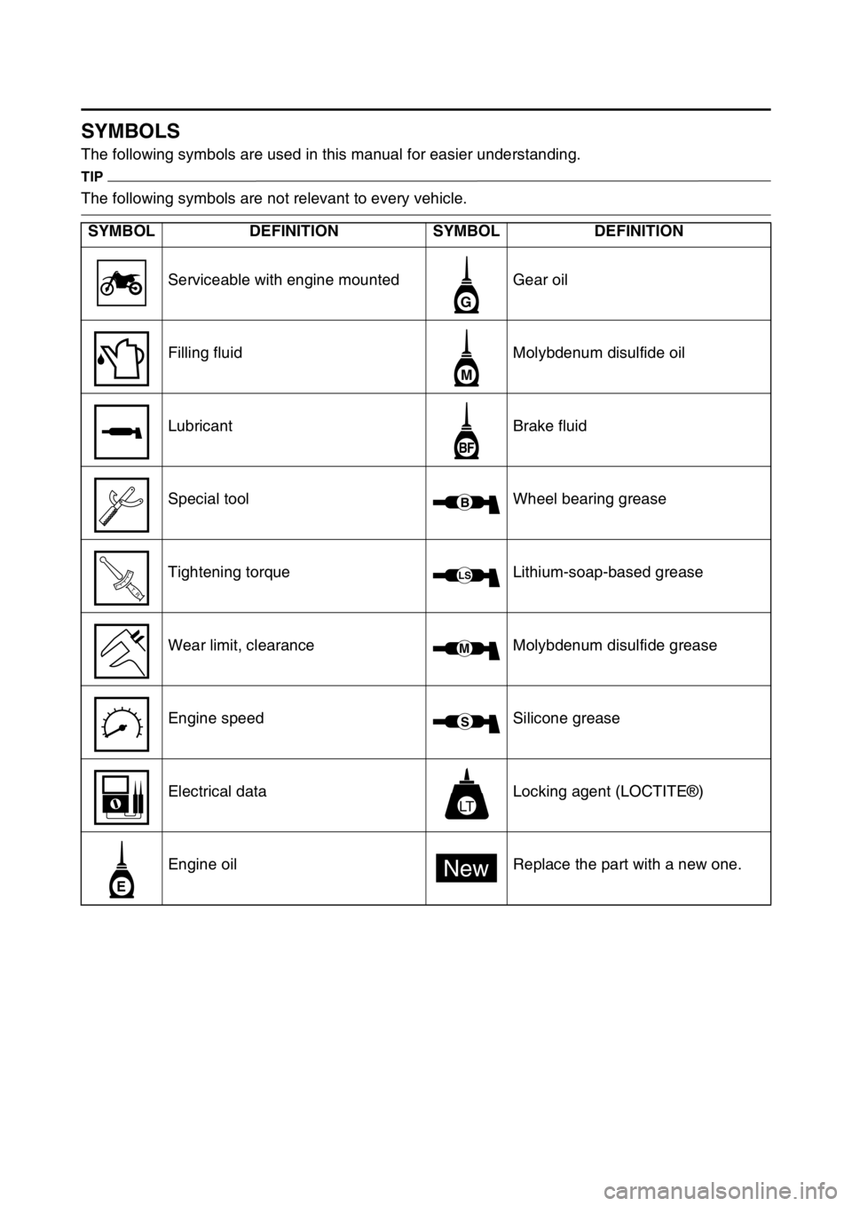
SYMBOLS
The following symbols are used in this manual for easier understanding.
TIP
The following symbols are not relevant to every vehicle.
SYMBOL DEFINITION SYMBOL DEFINITION
Serviceable with engine mounted Gear oil
Filling fluid Molybdenum disulfide oil
Lubricant Brake fluid
Special tool Wheel bearing grease
Tightening torque Lithium-soap-based grease
Wear limit, clearance Molybdenum disulfide grease
Engine speed Silicone grease
Electrical data Locking agent (LOCTITE®)
Engine oil Replace the part with a new one.
G
M
BF
B
T R..
LS
M
S
LT
E
New
Page 13 of 426

1
GENERAL INFORMATION
LOCATION OF IMPORTANT LABELS............................................................ 1-1
DESCRIPTION .................................................................................................. 1-4
IDENTIFICATION ............................................................................................. 1-5
VEHICLE IDENTIFICATION NUMBER ...................................................... 1-5
ENGINE SERIAL NUMBER ....................................................................... 1-5
VEHICLE EMISSION CONTROL INFORMATION LABEL......................... 1-5
INCLUDED PARTS .......................................................................................... 1-6
SPARK PLUG WRENCH ........................................................................... 1-6
NIPPLE WRENCH...................................................................................... 1-6
HANDLEBAR PROTECTOR .. .................................................................... 1-6
FUEL HOSE JOINT COVER ...................................................................... 1-6
COUPLER FOR CONNECTING OPTIONAL PART................................... 1-6
IMPORTANT INFORMATION .......................................................................... 1-7
PREPARATION FOR REMOVAL A ND DISASSEMBLY............................ 1-7
REPLACEMENT PARTS............................................................................ 1-7
GASKETS, OIL SEALS AND O-RINGS ..................................................... 1-8
LOCK WASHERS/PLATES AND COTTER PINS ...................................... 1-8
BEARINGS AND OIL SEALS ..................................................................... 1-8
CIRCLIPS ................................................................................................... 1-8
BASIC SERVICE INFORMATION .................................................................... 1-9
ELECTRICAL SYSTEM.......... .................................................................... 1-9
SPECIAL TOOLS ........................................................................................... 1-13
CONTROL FUNCTIONS ................................................................................ 1-18
INDICATOR LIGHTS AND WARNING LIGHTS ....................................... 1-18
ENGINE STOP SWITCH .......................................................................... 1-18
START SWITCH....................................................................................... 1-18
CLUTCH LEVER ................................................................................... ... 1-18
SHIFT PEDAL .......................................................................................... 1-19
KICKSTARTER LEVER.......... .................................................................. 1-19
THROTTLE GRIP ..................................................................................... 1-19
FRONT BRAKE LEVER ........................................................................... 1-19
REAR BRAKE PEDAL.............................................................................. 1-19
SIDESTAND ............................................................................................. 1-20
STARTER KNOB/IDLE SCREW .............................................................. 1-20
FUEL TANK CAP ..................................................................................... 1-20
Page 22 of 426
IMPORTANT INFORMATION
1-8
EAS2GC1022GASKETS, OIL SEALS AND O-RINGS
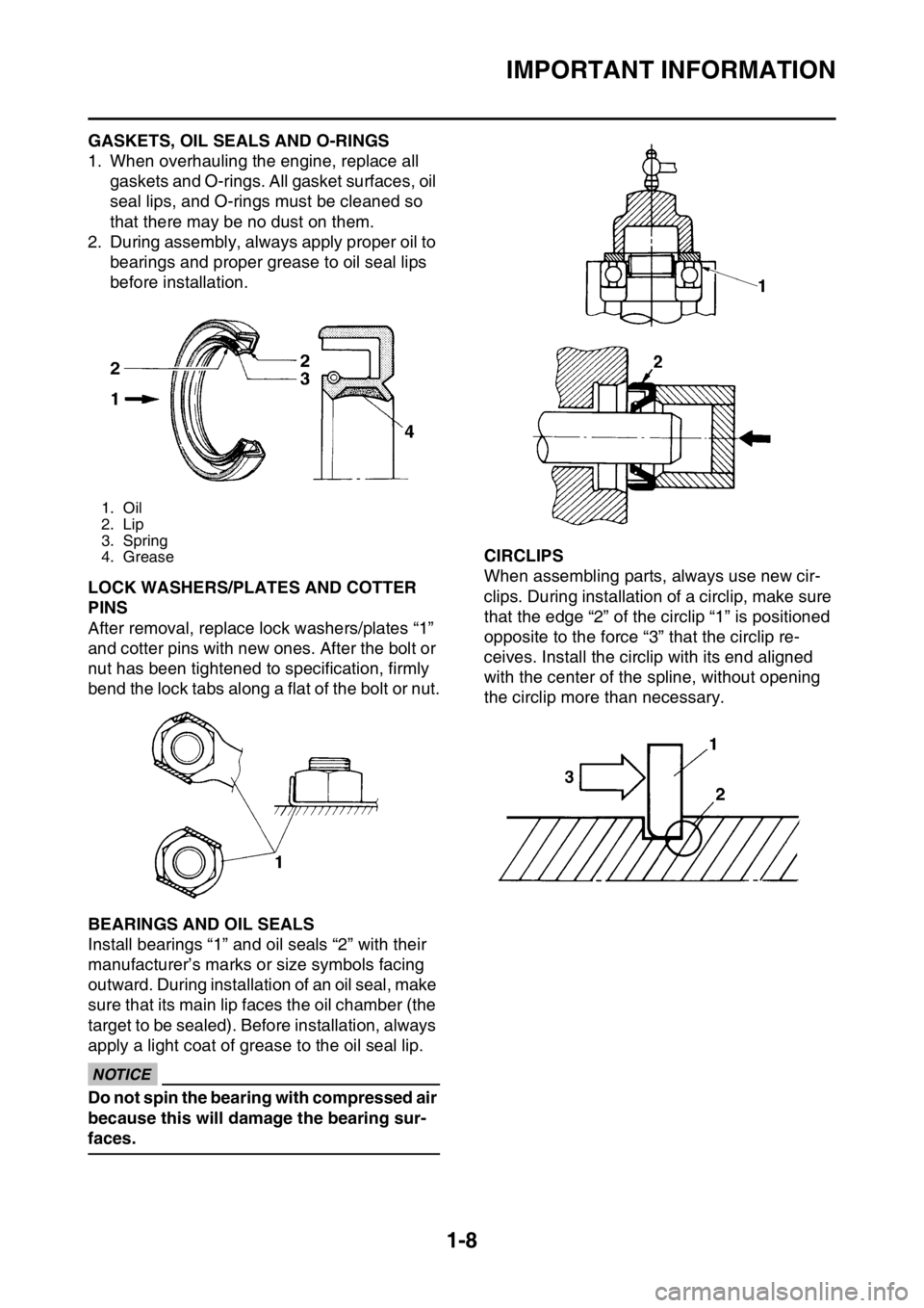
1. When overhauling the engine, replace all gaskets and O-rings. All gasket surfaces, oil
seal lips, and O-rings must be cleaned so
that there may be no dust on them.
2. During assembly, always apply proper oil to bearings and proper grease to oil seal lips
before installation.
EAS2GC1023LOCK WASHERS/PLATES AND COTTER
PINS
After removal, replace lock washers/plates “1”
and cotter pins with new ones. After the bolt or
nut has been tightened to specification, firmly
bend the lock tabs along a flat of the bolt or nut.
EAS2GC1024BEARINGS AND OIL SEALS
Install bearings “1” and oil seals “2” with their
manufacturer’s marks or size symbols facing
outward. During installation of an oil seal, make
sure that its main lip faces the oil chamber (the
target to be sealed). Before installation, always
apply a light coat of grease to the oil seal lip.
ECA
NOTICE
Do not spin the bearing with compressed air
because this will damage the bearing sur-
faces.
EAS2GC1025CIRCLIPS
When assembling parts, always use new cir-
clips. During installation of a circlip, make sure
that the edge “2” of the circlip “1” is positioned
opposite to the force “3” that the circlip re-
ceives. Install the circ lip with its end aligned
with the center of the spline, without opening
the circlip more than necessary.
1. Oil
2. Lip
3. Spring
4. Grease
Page 25 of 426
BASIC SERVICE INFORMATION
1-11
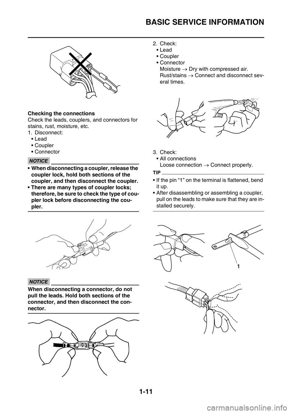
Checking the connections
Check the leads, couplers, and connectors for
stains, rust, moisture, etc.
1. Disconnect:• Lead
• Coupler
• Connector
ECA
NOTICE
• When disconnecting a coupler, release the
coupler lock, hold both sections of the
coupler, and then disconnect the coupler.
• There are many types of coupler locks; therefore, be sure to check the type of cou-
pler lock before disconnecting the cou-
pler.
ECA
NOTICE
When disconnecting a connector, do not
pull the leads. Hold both sections of the
connector, and then disconnect the con-
nector. 2. Check:
• Lead
• Coupler
• ConnectorMoisture Dry with compressed air.
Rust/stains Connect and disconnect sev-
eral times.
3. Check: • All connectionsLoose connection Connect properly.
TIP
• If the pin “1” on the terminal is flattened, bend
it up.
• After disassembling or assembling a coupler,
pull on the leads to make sure that they are in-
stalled securely.
1
Page 35 of 426
MULTI-FUNCTION DISPLAY
1-21
EAS2GC1042
MULTI-FUNCTION DISPLAYEWA
WARNING
Be sure to stop the machine before making
any setting changes to the multi-function
display.
The multi-function display is equipped with the
following:
BASIC MODE:
• Speedometer
•Clock
• Two tripmeters (which shows the distance that has been traveled since it was last set to
zero)
RACE MODE:
• Timer (which shows the time that has been
accumulated since the start of timer measure-
ment)
• Tripmeter (which shows the accumulated travel distance in timer measurement)
• Change tripmeter digits (capable of change to
any given ones)
EAS2GC1043DESCRIPTION
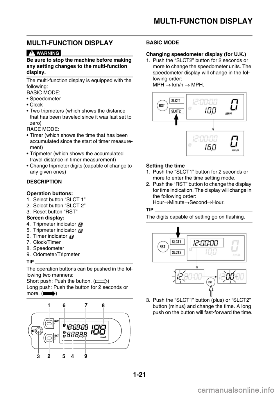
Operation buttons:
1. Select button “SLCT 1”
2. Select button “SLCT 2”
3. Reset button “RST”
Screen display:
4. Tripmeter indicator
5. Tripmeter indicator
6. Timer indicator
7. Clock/Timer
8. Speedometer
9. Odometer/Tripmeter
TIP
The operation buttons can be pushed in the fol-
lowing two manners:
Short push: Push the button. ( )
Long push: Push the button for 2 seconds or
more. ( )
EAS2GC1044BASIC MODE
Changing speedometer display (for U.K.)
1. Push the “SLCT2” button for 2 seconds or more to change the speedometer units. The
speedometer display will change in the fol-
lowing order:
MPH km/h MPH.
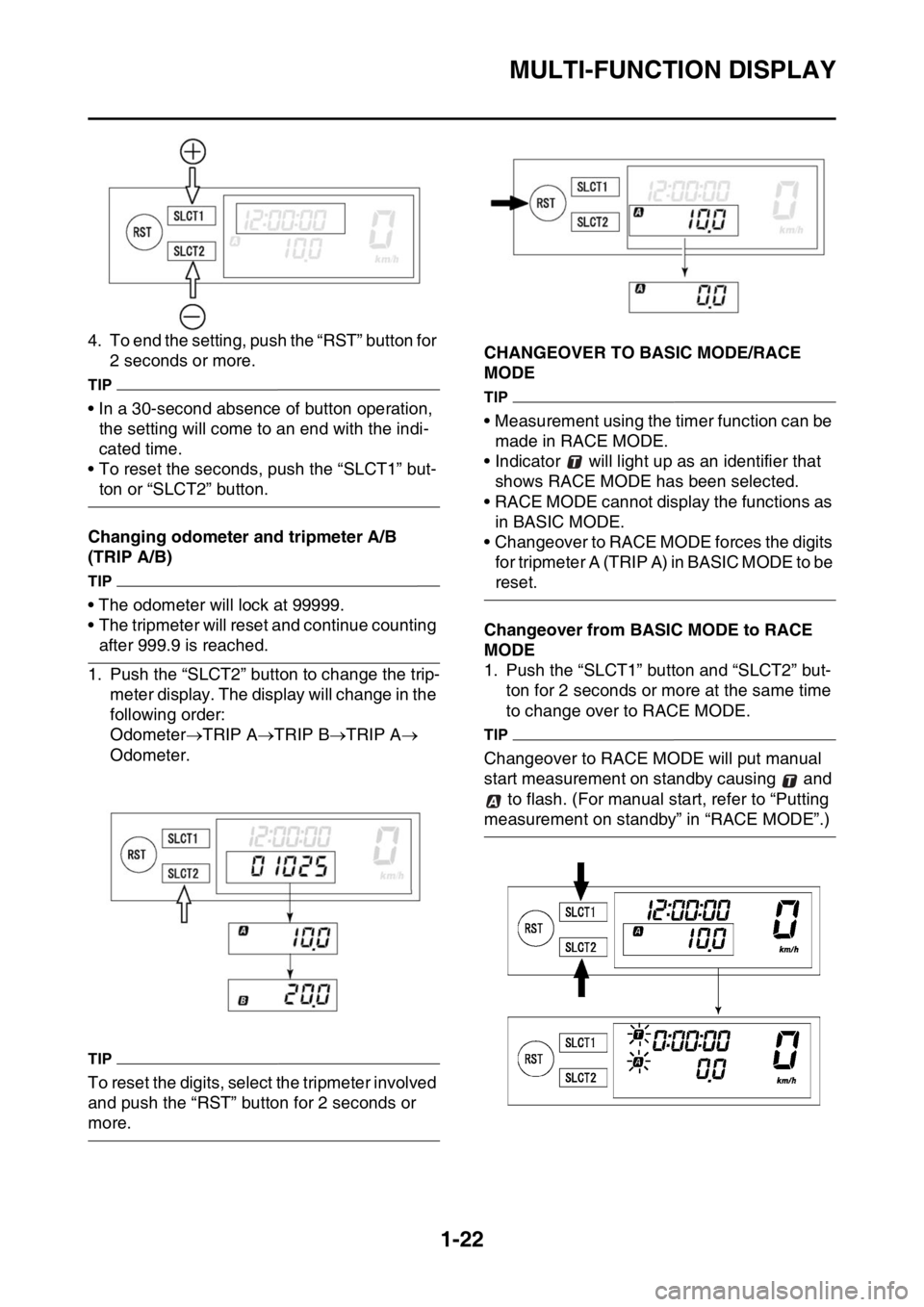
Setting the time
1. Push the “SLCT1” button for 2 seconds or more to enter the time setting mode.
2. Push the “RST” button to change the display for time indication. The display will change in
the following order:
Hour MinuteSecond Hour.
TIP
The digits capable of setting go on flashing.
3. Push the “SLCT1” button (plus) or “SLCT2”
button (minus) and change the time. A long
push on the button will fast-forward the time.
Page 36 of 426
MULTI-FUNCTION DISPLAY
1-22
4. To end the setting, push the “RST” button for 2 seconds or more.
TIP
• In a 30-second absence of button operation, the setting will come to an end with the indi-
cated time.
• To reset the seconds, push the “SLCT1” but-
ton or “SLCT2” button.
Changing odometer and tripmeter A/B
(TRIP A/B)
TIP
• The odometer will lock at 99999.
• The tripmeter will reset and continue counting
after 999.9 is reached.
1. Push the “SLCT2” button to change the trip- meter display. The display will change in the
following order:
Odometer TRIP A TRIP B TRIP A
Odometer.
TIP
To reset the digits, select the tripmeter involved
and push the “RST” button for 2 seconds or
more.
EAS2GC1045CHANGEOVER TO BASIC MODE/RACE
MODE
TIP
• Measurement using the timer function can be made in RACE MODE.
• Indicator will light up as an identifier that
shows RACE MODE has been selected.
• RACE MODE cannot display the functions as in BASIC MODE.
• Changeover to RACE MODE forces the digits for tripmeter A (TRIP A) in BASIC MODE to be
reset.
Changeover from BASIC MODE to RACE
MODE
1. Push the “SLCT1” button and “SLCT2” but- ton for 2 seconds or more at the same time
to change over to RACE MODE.
TIP
Changeover to RACE MODE will put manual
start measurement on standby causing and
to flash. (For manual start, refer to “Putting
measurement on standby” in “RACE MODE”.)
Page 40 of 426
MULTI-FUNCTION DISPLAY
1-26
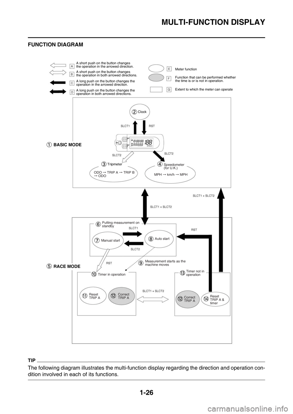
EAS2GC1047FUNCTION DIAGRAM
TIP
The following diagram illustrates the multi-function display regarding the direction and operation con-
dition involved in each of its functions.
A short push on the button changes
the operation in the arrowed direction.
A short push on the button changes
the operation in both arrowed directions.
A long push on the button changes the
operation in the arrowed direction.
A long push on the button changes the
operation in both arrowed directions. Meter function
Function that can be performed whether
the time is or is not in operation.
Extent to which the meter can operate
Clock
BASIC MODE
Tripmeter
ODO TRIP A TRIP B ODO
Speedometer
(for U.K.)
MPH
km/h MPH
Putting measurement on
standby
Manual startAuto start
RACE MODE
Timer in operation
Reset
TRIP A Correct
TRIP AMeasurement starts as the
machine moves
Timer not in
operation
Correct
TRIP A Reset
TRIP A &
timer
Page 41 of 426

MULTI-FUNCTION DISPLAY
1-27
A. A short push on the button changes the op-eration in the arrowed direction.
B. A short push on the button changes the op-
eration in both arrowed directions.
C. A long push on the button changes the oper- ation in the arrowed direction.
D. A long push on the button changes the oper- ation in both arrowed directions.
E. Meter function
F. Function that can be performed whether the
time is or is not in operation.
G. Extent to which the meter can operate
1. BASIC MODE
2. Clock
3. Trip meter
4. Speedometer (for U.K.)
5. RACE MODE
6. Putting measurement on standby
7. Manual start
8. Auto start
9. Measurement starts as the machine moves
10.Timer in operation
11.Reset TRIP A
12.Correct TRIP A
13.Timer not in operation
14.Reset TRIP A and timer
Page 55 of 426

ENGINE SPECIFICATIONS
2-4
Valve springFree length (intake) 40.76 mm (1.60 in)
Limit 38.72 mm (1.52 in)
Free length (exhaust) 36.94 mm (1.45 in)
Limit 35.09 mm (1.38 in)
Installed length (intake) 34.78 mm (1.37 in)
Installed length (exhaust) 30.83 mm (1.21 in)
Spring rate K1 (intake) 31.90 N/mm (3.25 kgf/mm, 182.15 lbf/in)
Spring rate K2 (intake) 41.37 N/mm (4.22 kgf/mm, 236.22 lbf/in)
Spring rate K1 (exhaust) 21.76 N/mm (2.22 kgf/mm, 124.25 lbf/in)
Spring rate K2 (exhaust) 28.12 N/mm (2.87 kgf/mm, 160.57 lbf/in)
Installed compression spring force (intake) 178.00–204.00 N (18.15–20.80 kgf,
40.01–45.86 lbf)
Installed compression spring force (exhaust) 124.00–142.00 N (12.64–14.48 kgf,
27.88–31.92 lbf)
Spring tilt (intake) 2.5 °/1.8 mm (2.5 °/0.07 in)
Spring tilt (exhaust) 2.5 °/1.6 mm (2.5 °/0.06 in)
Winding direction (intake) Clockwise
Winding direction (exhaust) Clockwise
Cylinder Bore 97.000–97.010 mm (3.8189–3.8193 in)
Taper limit 0.050 mm (0.0020 in)
Out of round limit 0.050 mm (0.0020 in)
PistonPiston-to-cylinder clearance 0.030–0.055 mm (0.0012–0.0022 in)
Limit 0.15 mm (0.006 in)
Diameter 96.955–96.970 mm (3.8171–3.8177 in)
Measuring point (from piston skirt bottom) 9.0 mm (0.35 in)
Offset 0.00 mm (0.0000 in)
Piston pin bore inside diameter 18.004–18.015 mm (0.7088–0.7093 in)
Limit 18.045 mm (0.7104 in)
Piston pin outside diameter 17.991–18.000 mm (0.7083–0.7087 in)
Limit 17.971 mm (0.7075 in)
Piston ringTop ring Ring type Barrel
Dimensions (B T) 1.00 3.30 mm (0.04 0.13 in)
End gap (installed) 0.20–0.30 mm (0.0079–0.0118 in)
Limit 0.55 mm (0.0217 in)
Ring side clearance 0.015–0.065 mm (0.0006–0.0026 in)
Limit 0.120 mm (0.0047 in)
2nd ring Ring type Taper
Dimensions (B T) 1.00 3.10 mm (0.04 0.12 in)
End gap (installed) 0.35–0.50 mm (0.0138–0.0197 in)
Limit 0.85 mm (0.0335 in)
Ring side clearance 0.020–0.060 mm (0.0008–0.0024 in)
Limit 0.120 mm (0.0047 in)
Oil ring
Dimensions (B T) 1.50 2.25 mm (0.06 0.89 in)
End gap (installed) 0.20–0.50 mm (0.0079–0.0197 in)
Page 59 of 426

CHASSIS SPECIFICATIONS
2-8
Rear brakeType Hydraulic single disc brake
Operation Right foot operation
Brake pedal position 5.0 mm (0.20 in)
Rear disc brake
Disc outside diameter thickness 245.0 4.0 mm (9.65 0.16 in)
Brake disc thickness limit 3.5 mm (0.14 in)
Brake disc runout limit (as measured on wheel) 0.15 mm (0.0059 in)
Brake pad lining thickness 6.4 mm (0.25 in)
Limit 1.0 mm (0.04 in)
Master cylinder inside diameter 11.0 mm (0.43 in)
Caliper cylinder inside diameter 25.40 mm (1.00 in)
Specified brake fluid DOT 4
Steering Steering bearing type Taper roller bearing
Center to lock angle (left) 43.0 °
Center to lock angle (right) 43.0 °
Front suspension
Type Telescopic fork
Spring/shock absorber type Coil spring/Hydraulic damper
Front fork travel 310.0 mm (12.20 in)
Fork spring free length 470.0 mm (18.50 in)
Limit 465.0 mm (18.31 in)
Fork spring installed length 470.0 mm (18.50 in)
Spring rate K1 4.50 N/mm (0.46 kgf/mm, 25.71 lbf/in)
Spring stroke K1 0.0–310.0 mm (0.00–12.20 in)
Inner tube outer diameter 48 mm (1.9 in)
Inner tube bending limit 0.2 mm (0.01 in)
Optional spring available Yes
Recommended oil Yamaha Suspension Oil S1
Quantity 545.0 cm
3 (18.43 US oz, 19.18 Imp.oz)
Rebound damping adjusting positions
Minimum 20 clicks out*
Standard 11 clicks out*
Maximum Fully turned in * With the adjuster fully turned in
Compression damping adjusting positions Minimum 20 clicks out*
Standard 13 clicks out*
Maximum Fully turned in
* With the adjuster fully turned in