YAMAHA XMAX 125 2022 Owners Manual
Manufacturer: YAMAHA, Model Year: 2022, Model line: XMAX 125, Model: YAMAHA XMAX 125 2022Pages: 118, PDF Size: 13.61 MB
Page 111 of 118
Consumer information
11-1
11
EAU53562
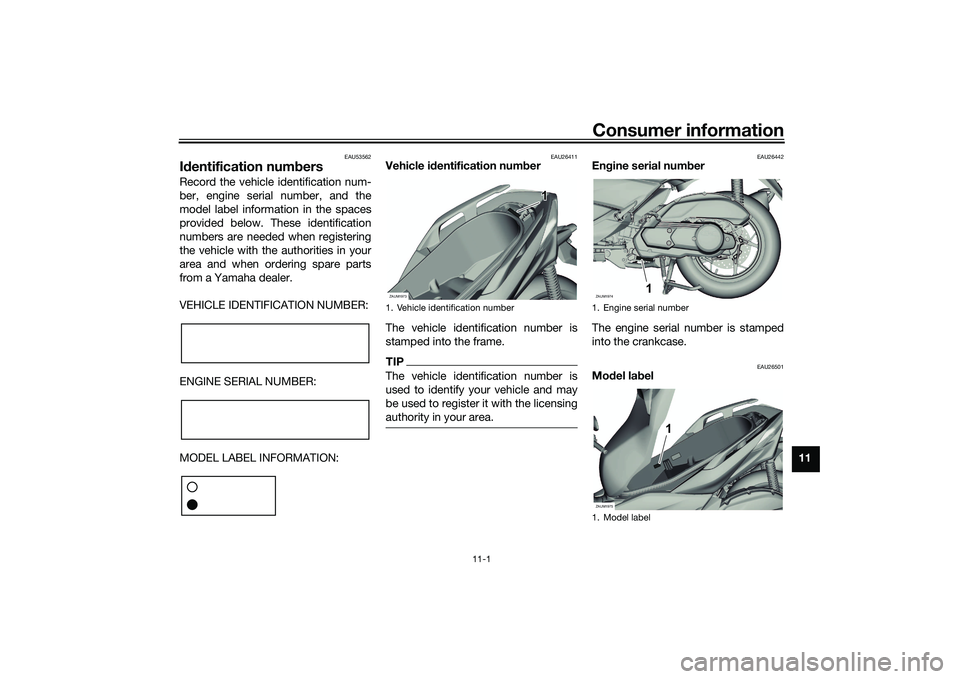
Id entification num bersRecord the vehicle identification num-
ber, engine serial number, and the
model label information in the spaces
provided below. These identification
numbers are needed when registering
the vehicle with the authorities in your
area and when ordering spare parts
from a Yamaha dealer.
VEHICLE IDENTIFICATION NUMBER:
ENGINE SERIAL NUMBER:
MODEL LABEL INFORMATION:
EAU26411
Vehicle i dentification num ber
The vehicle identification number is
stamped into the frame.TIPThe vehicle identification number is
used to identify your vehicle and may
be used to register it with the licensing
authority in your area.
EAU26442
En gine serial num ber
The engine serial number is stamped
into the crankcase.
EAU26501
Mo del la bel
1. Vehicle identification numberZAUM1973
1 1
1
1. Engine serial number
1. Model labelZAUM1974
1 1
1
ZAUM1975
1 1
1
UB9YE1E0.book Page 1 Tuesday, October 12, 2021 2:29 PM
Page 112 of 118
Consumer information
11-2
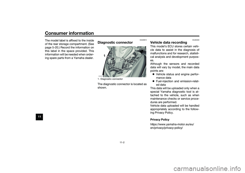
11The model label is affixed to the inside
of the rear storage compartment. (See
page 5-20.) Record the information on
this label in the space provided. This
information will be needed when order-
ing spare parts from a Yamaha dealer.
EAU69910
Dia
gnostic connectorThe diagnostic connector is located as
shown.
EAU85300
Vehicle data recor din gThis model’s ECU stores certain vehi-
cle data to assist in the diagnosis of
malfunctions and for research, statisti-
cal analysis and development purpos-
es.
Although the sensors and recorded
data will vary by model, the main data
points are:
Vehicle status and engine perfor-
mance data
Fuel-injection and emission-relat-
ed data
This data will be uploaded only when a
special Yamaha diagnostic tool is at-
tached to the vehicle, such as when
maintenance checks or service proce-
dures are performed.
Vehicle data uploaded will be handled
appropriately according to the follow-
ing Privacy Policy.
Privacy Policy
1. Diagnostic connectorZAUM1976
1 1
1
https://www.yamaha-motor.eu/eu/
en/privacy/privacy-policy/
UB9YE1E0.book Page 2 Tuesday, October 12, 2021 2:29 PM
Page 113 of 118
Consumer information
11-3
11
Yamaha will not disclose this data to a
third party except in the following cas-
es. In addition, Yamaha may provide
vehicle data to a contractor in order to
outsource services related to the han-
dling of vehicle data. Even in this case,
Yamaha will require the contractor to properly handle the vehicle data we
provided and Yamaha will appropriate-
ly manage the data. With the consent of the vehicle
owner
Where obligated by law
For use by Yamaha in litigation
When the data is not related to an
individual vehicle nor owner
UB9YE1E0.book Page 3 Tuesday, October 12, 2021 2:29 PM
Page 114 of 118
12-1
12
IndexAABS warning light ................................... 5-2
Acceleration and deceleration ................ 7-3
Activating the Stop and Start System .... 4-1
Air filter and V-belt case air filter
elements ............................................. 8-14
Anti-lock brake system (ABS) ............... 5-14
Auxiliary DC jack ................................... 5-26BBattery .................................................. 8-26
Brake fluid, changing ............................ 8-22
Brake fluid level, checking .................... 8-21
Brake lever, front .................................. 5-14
Brake lever, rear.................................... 5-14
Brake levers, lubricating ....................... 8-23
Braking.................................................... 7-3CCables, checking and lubricating ......... 8-23
Canister................................................. 8-10
Care ........................................................ 9-1
Catalytic converter ................................ 5-20
Centerstand and sidestand, checking and lubricating .................................... 8-24
Coolant ................................................. 8-13DData recording, vehicle ......................... 11-2
Diagnostic connector............................ 11-2
Dimmer/Pass switch ............................. 5-12EEmergency mode.................................. 8-34
Engine break-in....................................... 7-1
Engine oil and oil strainer...................... 8-10
Engine overheating ............................... 8-33
Engine serial number ............................ 11-1
FFinal transmission oil ............................ 8-12
Front and rear brake lever free play, checking............................................. 8-19
Front and rear brake pads, checking ... 8-20
Front fork, checking ............................. 8-25
Front turn signal light............................ 8-29
Fuel ....................................................... 5-18
Fuel consumption, tips for reducing ...... 7-4
Fuel tank cap ........................................ 5-17
Fuel tank overflow hose ....................... 5-20
Fuses, replacing ................................... 8-27HHandlebar position, adjusting .............. 5-25
Handlebar switches .............................. 5-12
Hazard switch....................................... 5-13
High beam indicator light ....................... 5-1
Horn switch .......................................... 5-13IIdentification numbers .......................... 11-1
Ignition circuit cut-off system ............... 5-27
Indicator lights and warning lights ......... 5-1KKey, handling of smart and mechanical keys ...................................................... 3-3LLicense plate light bulb, replacing........ 8-30MMain switch ............................................ 3-8
Maintenance and lubrication, periodic ... 8-4
Maintenance, emission control system.................................................. 8-3
Malfunction indicator light (MIL) ............. 5-1
Matte color, caution ............................... 9-1 Model label ...........................................11-1
Multi-function display .............................5-4
OOperating range of the smart key
system ..................................................3-2PPanel, removing and installing ................8-8
Parking ....................................................7-4
Part locations ..........................................2-1
Precautions when using the Stop and Start System .........................................4-3SSafe-riding points....................................1-5
Safety information ...................................1-1
Shock absorber assemblies, adjusting .............................................5-25
Sidestand ..............................................5-27
Smart key ................................................3-5
Smart key battery, replacing ...................3-6
Smart key system ...................................3-1
Smart key system indicator light.............5-2
Smart key system, troubleshooting ......8-31
Spark plug, checking ..............................8-9
Specifications .......................................10-1
Speedometer ..........................................5-3
Starting off ..............................................7-3
Starting the engine ..................................7-2
Steering, checking ................................8-25
Stop and Start System............................4-1
Stop and Start System indicator light .....5-2
Stop and Start System operation ...........4-1
Stop and Start System switch ..............5-13
Stop/Run/Start switch ..........................5-13
Storage ...................................................9-3
UB9YE1E0.book Page 1 Tuesday, October 12, 2021 2:29 PM
Page 115 of 118
Index
12-2
12
Storage compartments......................... 5-20TTachometer ............................................ 5-3
Throttle grip and cable, checking and
lubricating........................................... 8-23
Throttle grip free play, checking ........... 8-17
Tires ...................................................... 8-17
Tool kit .................................................... 8-2
Traction control system ........................ 5-15
Traction control system indicator light ... 5-2
TRIP/INFO switch ................................. 5-13
Troubleshooting.................................... 8-31
Troubleshooting chart .......................... 8-32
Turn signal indicator lights ..................... 5-1
Turn signal switch................................. 5-13VValve clearance .................................... 8-17
V-belt, checking.................................... 8-22
Vehicle identification number ............... 11-1
Vehicle lights ........................................ 8-29WWheel bearings, checking .................... 8-26
Wheels .................................................. 8-19
Windshield ............................................ 5-22
UB9YE1E0.book Page 2 Tuesday, October 12, 2021 2:29 PM
Page 116 of 118

A5-yoko_Blank.fm Page 1 Thursday, December 8, 2011 2:18 PM
Page 117 of 118

A5-yoko_Blank.fm Page 1 Thursday, December 8, 2011 2:18 PM
Page 118 of 118

PRINTED IN FRANCE2021.09 (E)
PANTONE285C
MBK IndustrieZ.I. de Rouvroy 02100 Saint QuentinSAS au capital de 14 000 000 €
Original instructions