coolant YAMAHA XMAX 300 2017 Owners Manual
[x] Cancel search | Manufacturer: YAMAHA, Model Year: 2017, Model line: XMAX 300, Model: YAMAHA XMAX 300 2017Pages: 116, PDF Size: 4.1 MB
Page 5 of 116

Table of contents
Safety information ............................1-1
Further safe-riding points ................1-5
Description ........................................2-1
Left view ..........................................2-1
Right view........................................2-2
Controls and instruments ................2-3
Smart key system ............................3-1
Smart key system............................3-1
Operating range of the smart key system .........................................3-2
Handling of the smart key and mechanical keys ..........................3-3
Smart key ........................................3-5
Replacing the smart key battery .....3-6
Main switch .....................................3-8
Instrument an d control functions ....4-1
Indicator lights and warning
lights ............................................4-1
Speedometer...................................4-2
Tachometer .....................................4-3
Multi-function display......................4-3
Handlebar switches.......................4-12
Front brake lever ...........................4-13
Rear brake lever ............................4-14
ABS ...............................................4-14
Traction control system.................4-15
Fuel tank cap.................................4-17
Fuel................................................4-18
Fuel tank overflow hose ................4-19
Catalytic converters .....................4-20
Storage compartments .................4-20
Windshield.....................................4-22
Handlebar position .......................4-25
Adjusting the shock absorber assemblies .................................4-25
Sidestand ......................................4-26
Ignition circuit cut-off system........4-27
Auxiliary DC jack ..........................4-29 For your safety – pre-operation
checks
............................................... 5-1
Operation an d important ri din g
points ................................................. 6-1
Starting the engine.......................... 6-2
Starting off ...................................... 6-3
Acceleration and deceleration ........ 6-3
Braking............................................ 6-4
Tips for reducing fuel consumption................................ 6-4
Engine break-in ............................... 6-5
Parking ............................................ 6-5
Perio dic maintenance an d
a d justment ........................................ 7-1
Owner’s tool kit ............................... 7-2
Periodic maintenance chart for the
emission control system.............. 7-3
General maintenance and
lubrication chart........................... 7-4
Removing and installing the panel ............................................ 7-7
Checking the spark plug ................. 7-8
Canister........................................... 7-9
Engine oil and oil filter element ....... 7-9
Final transmission oil .................... 7-12
Coolant ......................................... 7-13
Air filter and V-belt case air filter elements .................................... 7-14
Checking the throttle grip free play ............................................ 7-18
Valve clearance ............................. 7-19
Tires .............................................. 7-19
Cast wheels .................................. 7-21
Checking the front and rear brake lever free play ............................ 7-22
Checking the front and rear brake
pads........................................... 7-23
Checking the brake fluid level....... 7-23
Changing the brake fluid............... 7-24
Checking the V-belt ...................... 7-25
Checking and lubricating the cables ........................................ 7-25
Checking and lubricating the
throttle grip and cable ............... 7-26
UB74E0E0.book Page 1 Tuesday, May 2, 2017 1:04 PM
Page 12 of 116
Description
2-1
2
EAU63371
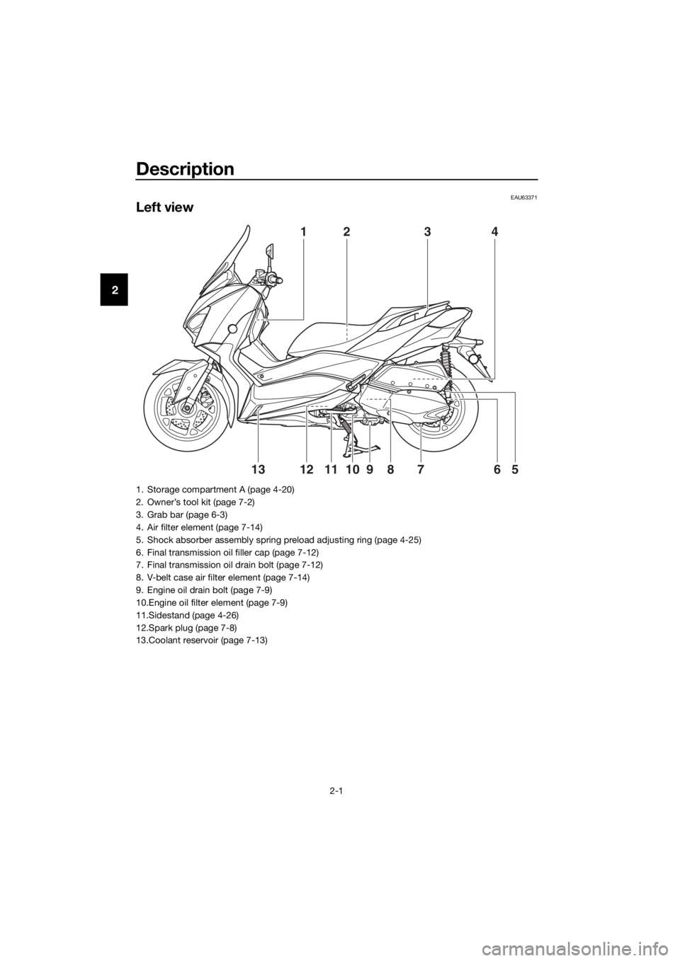
Left view
41
5610812791113
23
1. Storage compartment A (page 4-20)
2. Owner’s tool kit (page 7-2)
3. Grab bar (page 6-3)
4. Air filter element (page 7-14)
5. Shock absorber assembly spring preload adjusting ring (page 4-25)
6. Final transmission oil filler cap (page 7-12)
7. Final transmission oil drain bolt (page 7-12)
8. V-belt case air filter element (page 7-14)
9. Engine oil drain bolt (page 7-9)
10.Engine oil filter element (page 7-9)
11.Sidestand (page 4-26)
12.Spark plug (page 7-8)
13.Coolant reservoir (page 7-13)
UB74E0E0.book Page 1 Tuesday, May 2, 2017 1:04 PM
Page 29 of 116

Instrument and control functions
4-3
4
EAU63551
Tachometer
The electric tachometer allows the rid-
er to monitor the engine speed and
keep it within the ideal power range.
When the vehicle power is turned on,
the tachometer needle will sweep once
across the r/min range and then return
to zero r/min in order to test the electri-
cal circuit.
NOTICE
ECA10032
Do not operate the en gine in the ta-
chometer red zone.
Re d zone: 9000 r/min an d a bove
EAU78484
Multi-function d isplay
WARNING
EWA12423
Be sure to stop the vehicle before
makin g any settin g chan ges to the
multi-function meter unit. Chang ing
settin gs while ri din g can d istract the
operator an d increase the risk of an
acci dent.
The “TRIP/INFO” switch is located on
the right side of the handlebar. This
switch allows you to control or change
the settings of the multi-function meter
unit. To use the “TRIP” switch, move
the “TRIP/INFO” switch in direction (a).
To use the “INFO” switch, move the
“TRIP/INFO” switch in direction (b).
1. Tachometer
2. Tachometer red zone
1
2
1. Fuel meter
2. Information display
3. Coolant temperature meter
4. Clock
5. Tripmeter display
6. Icy road warning indicator “ ”
2
3
4
1
6
5
UB74E0E0.book Page 3 Tuesday, May 2, 2017 1:04 PM
Page 30 of 116

Instrument and control functions
4-4
4 The multi-function display is equipped
with the following:
�z clock
�z fuel meter
�z coolant temperature meter
�z tripmeter display
�z information display
TIP
For the UK: To switch the displays be-
tween kilometers and miles, turn the
main switch to “ON” while pushing the
“INFO” switch, and then continue to
push the “INFO” switch for eight sec-
onds.
Clock
The clock uses a 24-hour time system.
To set the clock
1. Turn the main switch to “OFF”. 2. Push and hold the “TRIP” switch.
3. Turn the main switch to “ON”
while pushing the “TRIP” switch,
and then continue to push the
“TRIP” switch for eight seconds.
The hour digits will start flashing.
4. Use the “TRIP” switch to set the hours.
5. Push the “TRIP” switch for three seconds, and then release it. The
minute digits will start flashing.
6. Use the “TRIP” switch to set the minutes.
7. Push the “TRIP” switch for three seconds, and then release it to
start the clock.
Fuel meter
The fuel meter indicates the amount of
fuel in the fuel tank. The segments of
the fuel meter disappear from “F” (full)
towards “E” (empty) as the fuel level
decreases. When the last segment of
the fuel meter starts flashing, refuel as
soon as possible.
TIP
�z If a problem is detected in the fuel
meter, the all segments will flash
repeatedly. If this occurs, have a
Yamaha dealer check the vehicle.
1. “TRIP/INFO” switch
1. Clock
1 (b)
(a)
1
1. Fuel meter
1
UB74E0E0.book Page 4 Tuesday, May 2, 2017 1:04 PM
Page 31 of 116
Instrument and control functions
4-5
4
�z
When approximately 2.4 L (0.63
US gal, 0.53 Imp.gal) of fuel re-
mains in the fuel tank, the last seg-
ment of the fuel meter will start
flashing. The display will automat-
ically change to the fuel reserve
tripmeter “F Trip” and start count-
ing the distance traveled from that
point.
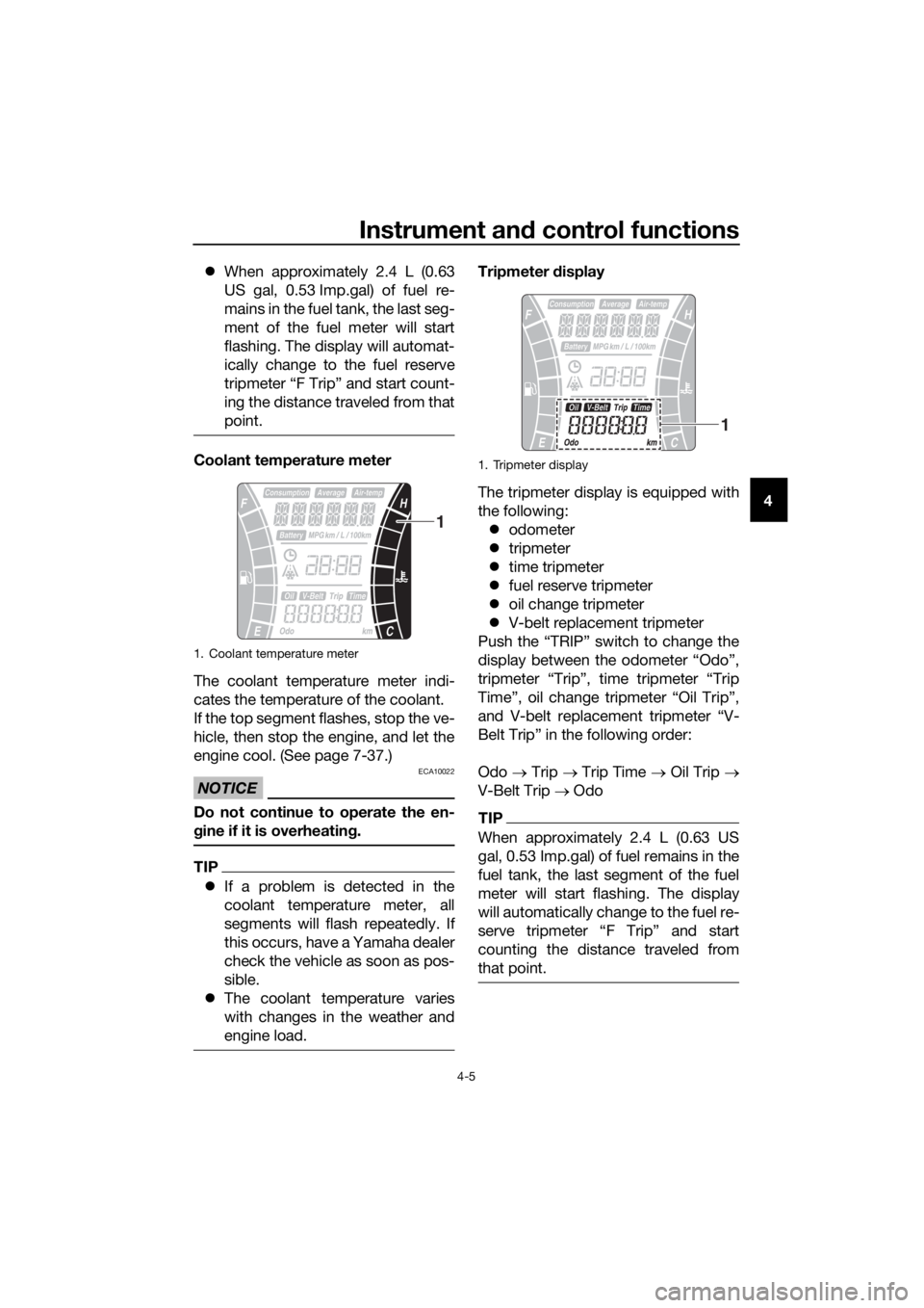
Coolant temperature meter
The coolant temperature meter indi-
cates the temperature of the coolant.
If the top segment flashes, stop the ve-
hicle, then stop the engine, and let the
engine cool. (See page 7-37.)
NOTICE
ECA10022
Do not continue to operate the en-
gine if it is overheatin g.
TIP
�z If a problem is detected in the
coolant temperature meter, all
segments will flash repeatedly. If
this occurs, have a Yamaha dealer
check the vehicle as soon as pos-
sible.
�z The coolant temperature varies
with changes in the weather and
engine load.
Tripmeter display
The tripmeter display is equipped with
the following: �z odometer
�z tripmeter
�z time tripmeter
�z fuel reserve tripmeter
�z oil change tripmeter
�z V-belt replacement tripmeter
Push the “TRIP” switch to change the
display between the odometer “Odo”,
tripmeter “Trip”, time tripmeter “Trip
Time”, oil change tripmeter “Oil Trip”,
and V-belt replacement tripmeter “V-
Belt Trip” in the following order:
Odo → Trip → Trip Time → Oil Trip →
V-Belt Trip → Odo
TIP
When approximately 2.4 L (0.63 US
gal, 0.53 Imp.gal) of fuel remains in the
fuel tank, the last segment of the fuel
meter will start flashing. The display
will automatically change to the fuel re-
serve tripmeter “F Trip” and start
counting the distance traveled from
that point.
1. Coolant temperature meter
1
1. Tripmeter display
1
UB74E0E0.book Page 5 Tuesday, May 2, 2017 1:04 PM
Page 37 of 116
Instrument and control functions
4-11
4
TIP
If traveling at speeds under 10 km/h (6
mi/h), “_ _._” is displayed.
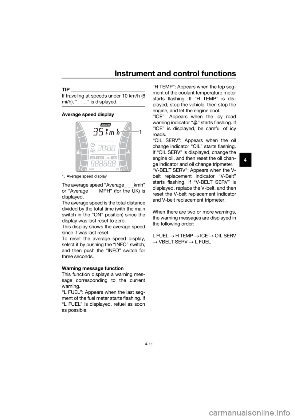
Avera ge speed d isplay
The average speed “Average_ _ _kmh”
or “Average_ _ _MPH” (for the UK) is
displayed.
The average speed is the total distance
divided by the total time (with the main
switch in the “ON” position) since the
display was last reset to zero.
This display shows the average speed
since it was last reset.
To reset the average speed display,
select it by pushing the “INFO” switch,
and then push the “INFO” switch for
three seconds.
Warnin g messa ge function
This function displays a warning mes-
sage corresponding to the current
warning.
“L FUEL”: Appears when the last seg-
ment of the fuel meter starts flashing. If
“L FUEL” is displayed, refuel as soon
as possible. “H TEMP”: Appears when the top seg-
ment of the coolant temperature meter
starts flashing. If “H TEMP” is dis-
played, stop the vehicle, then stop the
engine, and let the engine cool.
“ICE”: Appears when the icy road
warning indicator “ ” starts flashing. If
“ICE” is displayed, be careful of icy
roads.
“OIL SERV”: Appears when the oil
change indicator “OIL” starts flashing.
If “OIL SERV” is displayed, change the
engine oil, and then reset the oil chan-
ge indicator and oil change tripmeter.
“V-BELT SERV”: Appears when the V-
belt replacement indicator “V-Belt”
starts flashing. If “V-BELT SERV” is
displayed, replace the V-belt, and then
reset the V-belt replacement indicator
and V-belt replacement tripmeter.
When there are two or more warnings,
the warning messages are displayed in
the following order:
L FUEL
→ H TEMP → ICE → OIL SERV
→ VBELT SERV → L FUEL
1. Average speed display
1
UB74E0E0.book Page 11 Tuesday, May 2, 2017 1:04 PM
Page 56 of 116
For your safety – pre-operation checks
5-1
5
EAU63440
Inspect your vehicle each time you use it to make sure the vehicle is in safe oper-
ating condition. Always follow the inspection and maintenance procedures and
schedules described in the Owner’s Manual.
WARNING
EWA11152
Failure to inspect or maintain the vehicle properly increases the possibility
of an acci dent or equipment d amage. Do not operate the vehicle if you fin d
any pro blem. If a pro blem cannot be correcte d b y the proce dures provi ded
in this manual, have the vehicle inspecte d b y a Yamaha dealer.
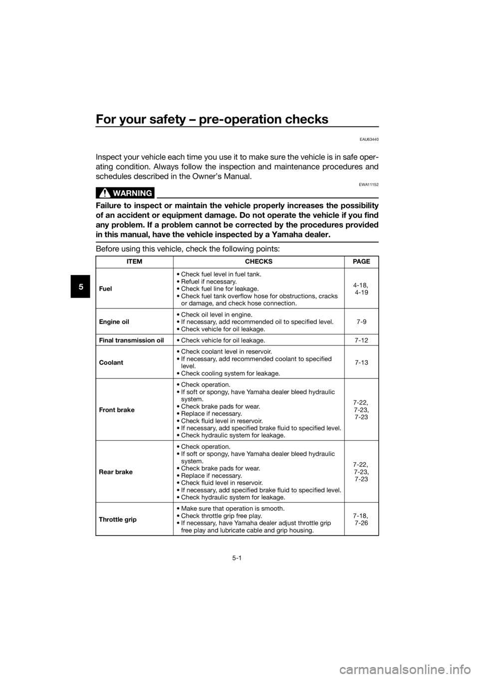
Before using this vehicle, check the following points:
ITEM CHECKSPAGE
Fuel • Check fuel level in fuel tank.
• Refuel if necessary.
• Check fuel line for leakage.
• Check fuel tank overflow hose for obstructions, cracks
or damage, and check hose connection. 4-18,
4-19
En gine oil • Check oil level in engine.
• If necessary, add recommended oil to specified level.
• Check vehicle for oil leakage. 7-9
Final transmission oil • Check vehicle for oil leakage. 7-12
Coolant • Check coolant level in reservoir.
• If necessary, add recommended coolant to specified
level.
• Check cooling system for leakage. 7-13
Front brake • Check operation.
• If soft or spongy, have Yamaha dealer bleed hydraulic
system.
• Check brake pads for wear.
• Replace if necessary.
• Check fluid level in reservoir.
• If necessary, add specified brake fluid to specified level.
• Check hydraulic system for leakage. 7-22,
7-23, 7-23
Rear brake • Check operation.
• If soft or spongy, have Yamaha dealer bleed hydraulic
system.
• Check brake pads for wear.
• Replace if necessary.
• Check fluid level in reservoir.
• If necessary, add specified brake fluid to specified level.
• Check hydraulic system for leakage. 7-22,
7-23, 7-23
Throttle grip • Make sure that operation is smooth.
• Check throttle grip free play.
• If necessary, have Yamaha dealer adjust throttle grip
free play and lubricate cable and grip housing. 7-18,
7-26
UB74E0E0.book Page 1 Tuesday, May 2, 2017 1:04 PM
Page 68 of 116

Periodic maintenance an d a djustment
7-5
7
14 *Steerin g b earin gs • Check bearing assemblies for
looseness. √√ √
• Moderately repack with lithium- soap-based grease. √√
15 *Chassis fasteners • Make sure that all nuts, bolts
and screws are properly tight-
ened. √√√√√
16 Front an
d rear
b rake lever pivot
shaft • Lubricate with silicone grease.
√√√√√
17 Si
destan d, center-
stan d • Check operation.
• Lubricate with lithium-soap-
based grease. √√√√√
18 *Sidestan d switch • Check operation and replace if
necessary. √√√√√√
19 *Front fork • Check operation and for oil
leakage.
• Replace if necessary. √√√√
20 *Shock ab
sorber
assem blies • Check operation and for oil
leakage.
• Replace if necessary. √√√√
21 En gine oil • Change (warm engine before
draining).
• Check oil level and vehicle for oil leakage. At the initial interval and
when the oil change indi-
cator flashes or comes on [every 5000km (3000 mi)]. √
22 En
gine oil filter el-
ement • Replace.
√√√
23 *Final transmission
oil • Check vehicle for oil leakage.
√√√√√
• Change. √√√
24 *Co
olin g syst
em• Check coolant level and vehicle
for coolant leakage. √√√√√
• Change. Every 3 years
25 *V-belt • Replace. When the V-belt replacement
indicator flashes [every 20000 km (12000 mi)]
26 *Front an
d rear
b rake switches • Check operation.
√√√√√√
NO. ITEM
X 1000 km
CHECK OR
MAINTENANCE JOB
X 1000 mi ODOMETER
READINGS
ANNUAL CHECK
110203040
0.6 6 12 18 24
UB74E0E0.book Page 5 Tuesday, May 2, 2017 1:04 PM
Page 76 of 116
Periodic maintenance an d a djustment
7-13
7
EAU20071
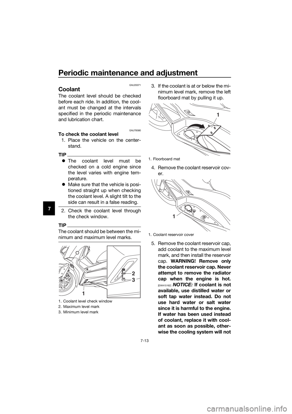
Coolant
The coolant level should be checked
before each ride. In addition, the cool-
ant must be changed at the intervals
specified in the periodic maintenance
and lubrication chart.
EAU78580To check the coolant level
1. Place the vehicle on the center- stand.
TIP
�zThe coolant level must be
checked on a cold engine since
the level varies with engine tem-
perature.
�z Make sure that the vehicle is posi-
tioned straight up when checking
the coolant level. A slight tilt to the
side can result in a false reading.
2. Check the coolant level through
the check window.
TIP
The coolant should be between the mi-
nimum and maximum level marks.
3. If the coolant is at or below the mi-nimum level mark, remove the left
floorboard mat by pulling it up.
4. Remove the coolant reservoir cov- er.
5. Remove the coolant reservoir cap, add coolant to the maximum level
mark, and then install the reservoir
cap. WARNING! Remove only
the coolant reservoir cap. Never
attempt to remove the ra diator
cap when the en gine is hot.
[EWA15162] NOTICE: If coolant is not
availa ble, use distille d water or
soft tap water instea d. Do not
use har d water or salt water
since it is harmful to the en gine.
If water has been used instead
of coolant, replace it with cool-
ant as soon as possi ble, other-
wise the coolin g system will not
1. Coolant level check window
2. Maximum level mark
3. Minimum level mark
1
2
3
1. Floorboard mat
1. Coolant reservoir cover
1
1
UB74E0E0.book Page 13 Tuesday, May 2, 2017 1:04 PM
Page 77 of 116
Periodic maintenance an d a djustment
7-14
7
b
e protecte d a gainst frost an d
corrosion. If water has b een
a dde d to the coolant, have a
Yamaha dealer check the anti-
freeze content of the coolant as
soon as possi ble, otherwise the
effectiveness of the coolant will
b e red uced.
[ECA10473]
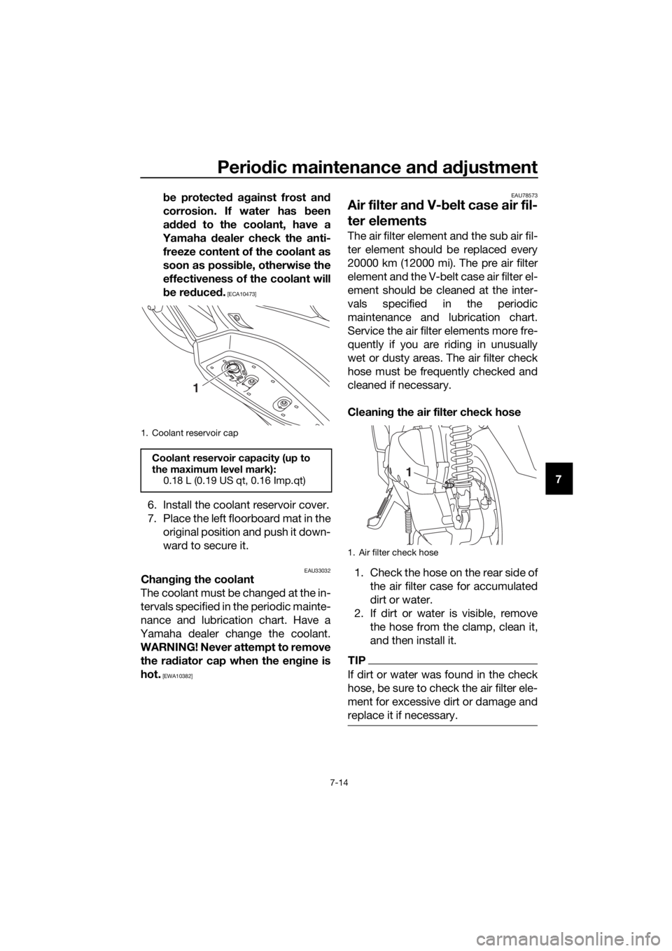
6. Install the coolant reservoir cover.
7. Place the left floorboard mat in the
original position and push it down-
ward to secure it.
EAU33032Chan gin g the coolant
The coolant must be changed at the in-
tervals specified in the periodic mainte-
nance and lubrication chart. Have a
Yamaha dealer change the coolant.
WARNING! Never attempt to remove the ra diator cap when the en gine is
hot.
[EWA10382] EAU78573
Air filter an
d V- belt case air fil-
ter elements
The air filter element and the sub air fil-
ter element should be replaced every
20000 km (12000 mi). The pre air filter
element and the V-belt case air filter el-
ement should be cleaned at the inter-
vals specified in the periodic
maintenance and lubrication chart.
Service the air filter elements more fre-
quently if you are riding in unusually
wet or dusty areas. The air filter check
hose must be frequently checked and
cleaned if necessary.
Cleanin g the air filter check hose
1. Check the hose on the rear side of the air filter case for accumulated
dirt or water.
2. If dirt or water is visible, remove the hose from the clamp, clean it,
and then install it.
TIP
If dirt or water was found in the check
hose, be sure to check the air filter ele-
ment for excessive dirt or damage and
replace it if necessary.
1. Coolant reservoir cap
Coolant reservoir capacity (up to
the maximum level mark):0.18 L (0.19 US qt, 0.16 Imp.qt)
1
1. Air filter check hose
1
UB74E0E0.book Page 14 Tuesday, May 2, 2017 1:04 PM