oil filter YAMAHA XMAX 300 2017 Owners Manual
[x] Cancel search | Manufacturer: YAMAHA, Model Year: 2017, Model line: XMAX 300, Model: YAMAHA XMAX 300 2017Pages: 116, PDF Size: 4.1 MB
Page 5 of 116

Table of contents
Safety information ............................1-1
Further safe-riding points ................1-5
Description ........................................2-1
Left view ..........................................2-1
Right view........................................2-2
Controls and instruments ................2-3
Smart key system ............................3-1
Smart key system............................3-1
Operating range of the smart key system .........................................3-2
Handling of the smart key and mechanical keys ..........................3-3
Smart key ........................................3-5
Replacing the smart key battery .....3-6
Main switch .....................................3-8
Instrument an d control functions ....4-1
Indicator lights and warning
lights ............................................4-1
Speedometer...................................4-2
Tachometer .....................................4-3
Multi-function display......................4-3
Handlebar switches.......................4-12
Front brake lever ...........................4-13
Rear brake lever ............................4-14
ABS ...............................................4-14
Traction control system.................4-15
Fuel tank cap.................................4-17
Fuel................................................4-18
Fuel tank overflow hose ................4-19
Catalytic converters .....................4-20
Storage compartments .................4-20
Windshield.....................................4-22
Handlebar position .......................4-25
Adjusting the shock absorber assemblies .................................4-25
Sidestand ......................................4-26
Ignition circuit cut-off system........4-27
Auxiliary DC jack ..........................4-29 For your safety – pre-operation
checks
............................................... 5-1
Operation an d important ri din g
points ................................................. 6-1
Starting the engine.......................... 6-2
Starting off ...................................... 6-3
Acceleration and deceleration ........ 6-3
Braking............................................ 6-4
Tips for reducing fuel consumption................................ 6-4
Engine break-in ............................... 6-5
Parking ............................................ 6-5
Perio dic maintenance an d
a d justment ........................................ 7-1
Owner’s tool kit ............................... 7-2
Periodic maintenance chart for the
emission control system.............. 7-3
General maintenance and
lubrication chart........................... 7-4
Removing and installing the panel ............................................ 7-7
Checking the spark plug ................. 7-8
Canister........................................... 7-9
Engine oil and oil filter element ....... 7-9
Final transmission oil .................... 7-12
Coolant ......................................... 7-13
Air filter and V-belt case air filter elements .................................... 7-14
Checking the throttle grip free play ............................................ 7-18
Valve clearance ............................. 7-19
Tires .............................................. 7-19
Cast wheels .................................. 7-21
Checking the front and rear brake lever free play ............................ 7-22
Checking the front and rear brake
pads........................................... 7-23
Checking the brake fluid level....... 7-23
Changing the brake fluid............... 7-24
Checking the V-belt ...................... 7-25
Checking and lubricating the cables ........................................ 7-25
Checking and lubricating the
throttle grip and cable ............... 7-26
UB74E0E0.book Page 1 Tuesday, May 2, 2017 1:04 PM
Page 12 of 116

Description
2-1
2
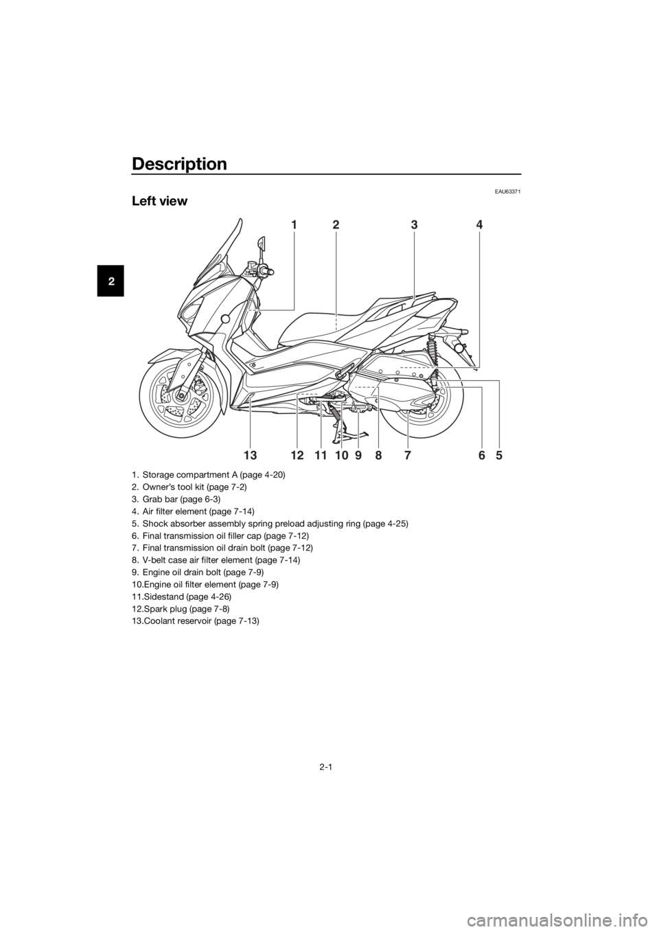
EAU63371
Left view
41
5610812791113
23
1. Storage compartment A (page 4-20)
2. Owner’s tool kit (page 7-2)
3. Grab bar (page 6-3)
4. Air filter element (page 7-14)
5. Shock absorber assembly spring preload adjusting ring (page 4-25)
6. Final transmission oil filler cap (page 7-12)
7. Final transmission oil drain bolt (page 7-12)
8. V-belt case air filter element (page 7-14)
9. Engine oil drain bolt (page 7-9)
10.Engine oil filter element (page 7-9)
11.Sidestand (page 4-26)
12.Spark plug (page 7-8)
13.Coolant reservoir (page 7-13)
UB74E0E0.book Page 1 Tuesday, May 2, 2017 1:04 PM
Page 62 of 116

Operation and important rid ing points
6-5
6
EAU16842
En gine break-in
There is never a more important period
in the life of your engine than the period
between 0 and 1600 km (1000 mi). For
this reason, you should read the fol-
lowing material carefully.
Since the engine is brand new, do not
put an excessive load on it for the first
1600 km (1000 mi). The various parts in
the engine wear and polish themselves
to the correct operating clearances.
During this period, prolonged full-throt-
tle operation or any condition that
might result in engine overheating
must be avoided.
EAU34323
0–1000 km (0–600 mi)
Avoid prolonged operation above 4500
r/min. NOTICE: After 1000 km (600
mi) of operation, be sure to replace
the en gine oil, final transmission oil
an d the oil filter element.
[ECA12932]
1000–1600 km (600–1000 mi)
Avoid prolonged operation above 5400
r/min.
1600 km (1000 mi) an d b eyon d
The vehicle can now be operated nor-
mally.
NOTICE
ECA10311
�z Keep the en gine spee d out of
the tachometer red zone.
�z If any en gine trou ble shoul d oc-
cur during the en gine break-in
period , imme diately have a
Yamaha dealer check the vehi-
cle.
EAUN1421
Parkin g
When parking, turn the vehicle power
off, and then turn the smart key off.
TIP
Even when the vehicle is parked in a lo-
cation partitioned by a fence or the
glass window of a shop, if the smart
key is within operating range, other
people will be able to start the engine
and operate the vehicle. Please turn
the smart key off when leaving the ve-
hicle. (See page 3-5.)
If the sidestand is lowered when the
engine is running, the engine will stop
and the beeper will sound for approxi-
mately 1 minute. To stop the beeper,
turn the vehicle power off or raise the
sidestand.
TIP
�zBefore leaving the vehicle, be sure
to turn the main switch to “OFF”
or “ ”. Otherwise, the battery may
discharge.
�z The sidestand alarm beeper can
be set to not activate. Please con-
tact your Yamaha dealer.
WARNING
EWA10312
�zSince the en gine an d exhaust
system can become very hot,
park in a place where ped estri-
ans or chil dren are not likely to
touch them and b e burne d.
�z Do not park on a slope or on soft
groun d, otherwise the vehicle
may overturn, increasin g the
risk of a fuel leak an d fire.
UB74E0E0.book Page 5 Tuesday, May 2, 2017 1:04 PM
Page 68 of 116

Periodic maintenance an d a djustment
7-5
7
14 *Steerin g b earin gs • Check bearing assemblies for
looseness. √√ √
• Moderately repack with lithium- soap-based grease. √√
15 *Chassis fasteners • Make sure that all nuts, bolts
and screws are properly tight-
ened. √√√√√
16 Front an
d rear
b rake lever pivot
shaft • Lubricate with silicone grease.
√√√√√
17 Si
destan d, center-
stan d • Check operation.
• Lubricate with lithium-soap-
based grease. √√√√√
18 *Sidestan d switch • Check operation and replace if
necessary. √√√√√√
19 *Front fork • Check operation and for oil
leakage.
• Replace if necessary. √√√√
20 *Shock ab
sorber
assem blies • Check operation and for oil
leakage.
• Replace if necessary. √√√√
21 En gine oil • Change (warm engine before
draining).
• Check oil level and vehicle for oil leakage. At the initial interval and
when the oil change indi-
cator flashes or comes on [every 5000km (3000 mi)]. √
22 En
gine oil filter el-
ement • Replace.
√√√
23 *Final transmission
oil • Check vehicle for oil leakage.
√√√√√
• Change. √√√
24 *Co
olin g syst
em• Check coolant level and vehicle
for coolant leakage. √√√√√
• Change. Every 3 years
25 *V-belt • Replace. When the V-belt replacement
indicator flashes [every 20000 km (12000 mi)]
26 *Front an
d rear
b rake switches • Check operation.
√√√√√√
NO. ITEM
X 1000 km
CHECK OR
MAINTENANCE JOB
X 1000 mi ODOMETER
READINGS
ANNUAL CHECK
110203040
0.6 6 12 18 24
UB74E0E0.book Page 5 Tuesday, May 2, 2017 1:04 PM
Page 69 of 116

Periodic maintenance an d a djustment
7-6
7
EAU79370
TIP
�z Engine air filter and V-belt air filter
• This model’s engine air filter is equipped with a disposable oil-coated pa- per element, which must not be cleaned with compressed air to avoid
damaging it.
• The engine air filter element and sub air filter element need to be replaced and the V-belt air filter element needs to be serviced more frequently when
riding in unusually wet or dusty areas.
�z Hydraulic brake service
• After disassembling the brake master cylinders and calipers, always chan- ge the fluid. Regularly check the brake fluid levels and fill the reservoirs as
required.
• Every two years replace the internal components of the brake master cyl- inders and calipers, and change the brake fluid.
• Replace the brake hoses every four years and if cracked or damaged.
27 *Movin
g parts an d
cab les • Lubricate.
√√√√√
28 *Throttle
grip hous-
in g an d cab le • Check operation and free play.
• Adjust the throttle cable free
play if necessary.
• Lubricate the throttle grip hous- ing and cable. √√√√√
29 *Li
ghts, si gnals an d
switches • Check operation.
• Adjust headlight beam.
√√√√√√
NO. ITEM
X 1000 km
CHECK OR
MAINTENANCE JOB
X 1000 mi
ODOMETER READINGS
ANNUAL CHECK
110203040
0.66121824
UB74E0E0.book Page 6 Tuesday, May 2, 2017 1:04 PM
Page 72 of 116

Periodic maintenance an d a djustment
7-9
7
EAU36112
Canister
This model is equipped with a canister
to prevent the discharging of fuel vapor
into the atmosphere. Before operating
this vehicle, make sure to check the
following:
�z Check each hose connection.
�z Check each hose and canister for
cracks or damage. Replace if
damaged.
�z Make sure that the canister
breather is not blocked, and if
necessary, clean it.
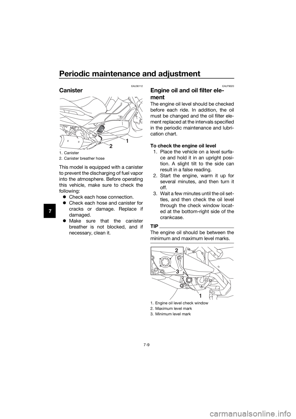
EAU79020
Engine oil an d oil filter ele-
ment
The engine oil level should be checked
before each ride. In addition, the oil
must be changed and the oil filter ele-
ment replaced at the intervals specified
in the periodic maintenance and lubri-
cation chart.
To check the en gine oil level
1. Place the vehicle on a level surfa- ce and hold it in an upright posi-
tion. A slight tilt to the side can
result in a false reading.
2. Start the engine, warm it up for several minutes, and then turn it
off.
3. Wait a few minutes until the oil set- tles, and then check the oil level
through the check window locat-
ed at the bottom-right side of the
crankcase.
TIP
The engine oil should be between the
minimum and maximum level marks.
1. Canister
2. Canister breather hose
2
1
1. Engine oil level check window
2. Maximum level mark
3. Minimum level mark
3
1
2
UB74E0E0.book Page 9 Tuesday, May 2, 2017 1:04 PM
Page 73 of 116

Periodic maintenance an d a djustment
7-10
7
4. If the engine oil is below the mini-
mum level mark, add sufficient oil
of the recommended type to raise
it to the correct level.
To chan ge the en gine oil (with or
without oil filter element replace-
ment) 1. Start the engine, warm it up for several minutes, and then turn it
off.
2. Place an oil pan under the engine to collect the used oil.
3. Remove the engine oil filler cap and its O-ring, and then remove
the engine oil drain bolt and its
gasket to drain the oil from the
crankcase.
4. Check the O-ring for damage, and replace it if necessary.
TIP
Skip steps 5–7 if the oil filter element is
not being replaced.
5. Remove the oil filter element coverby removing the bolts.
6. Remove and replace the oil filter element and O-ring.
1. Engine oil filler cap
2. O-ring
1
2
1. Engine oil drain bolt
2. Gasket
1. Bolt
2. Oil filter element cover
12
2
1
UB74E0E0.book Page 10 Tuesday, May 2, 2017 1:04 PM
Page 74 of 116

Periodic maintenance an d a djustment
7-11
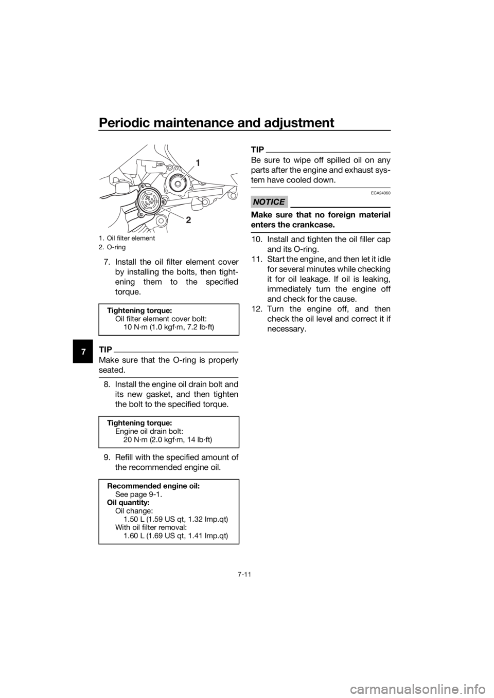
7 7. Install the oil filter element cover
by installing the bolts, then tight-
ening them to the specified
torque.TIP
Make sure that the O-ring is properly
seated.
8. Install the engine oil drain bolt andits new gasket, and then tighten
the bolt to the specified torque.
9. Refill with the specified amount of the recommended engine oil.
TIP
Be sure to wipe off spilled oil on any
parts after the engine and exhaust sys-
tem have cooled down.
NOTICE
ECA24060
Make sure that no forei gn material
enters the crankcase.
10. Install and tighten the oil filler cap and its O-ring.
11. Start the engine, and then let it idle for several minutes while checking
it for oil leakage. If oil is leaking,
immediately turn the engine off
and check for the cause.
12. Turn the engine off, and then check the oil level and correct it if
necessary.1. Oil filter element
2. O-ring
Tightenin g torque:
Oil filter element cover bolt: 10 N·m (1.0 kgf·m, 7.2 lb·ft)
Ti ghtenin g torque:
Engine oil drain bolt:
20 N·m (2.0 kgf·m, 14 lb·ft)
Recommen ded en gine oil:
See page 9-1.
Oil quantity: Oil change:
1.50 L (1.59 US qt, 1.32 Imp.qt)
With oil filter removal: 1.60 L (1.69 US qt, 1.41 Imp.qt)
1
2
UB74E0E0.book Page 11 Tuesday, May 2, 2017 1:04 PM
Page 108 of 116

Specifications
9-1
9
Dimensions:
Overall length:2185 mm (86.0 in)
Overall width:
775 mm (30.5 in)
Overall height: 1415/1465 mm (55.7/57.7 in)
Seat height: 795 mm (31.3 in)
Wheelbase:
1540 mm (60.6 in)
Ground clearance: 135 mm (5.31 in)
Minimum turning radius: 2.6 m (8.53 ft)
Wei ght:
Curb weight:
179 kg (395 lb)
Engine:
Combustion cycle:
4-stroke
Cooling system:
Liquid cooled
Valve train: SOHC
Number of cylinders: Single cylinder
Displacement:
292 cm³
Bore × stroke:
70.0 × 75.9 mm (2.76 × 2.99 in)
Compression ratio: 10.9 : 1
Starting system:
Electric starter
Lubrication system: Wet sump
Engine oil:
Recommended brand:
YAMALUBE
SAE viscosity grades: 10W-40
Recommended engine oil grade: API service SG type or higher, JASO
standard MA or MB
Engine oil quantity: Oil change:1.50 L (1.59 US qt, 1.32 Imp.qt)
With oil filter removal: 1.60 L (1.69 US qt, 1.41 Imp.qt)
Final transmission oil:
Type:Motor oil SAE 10W-30 type SE or higher or
Gear oil SAE 85W GL-3
Quantity: 0.20 L (0.21 US qt, 0.18 Imp.qt)
Coolant quantity:
Coolant reservoir (up to the maximum level
mark):
0.18 L (0.19 US qt, 0.16 Imp.qt)
Radiator (including all routes): 1.10 L (1.16 US qt, 0.97 Imp.qt)
Air filter:
Air filter element:
Oil-coated paper element
Fuel:
Recommended fuel:Regular unleaded gasoline (Gasohol [E10]
acceptable)
Fuel tank capacity: 13 L (3.4 US gal, 2.9 Imp.gal)
Fuel reserve amount: 2.4 L (0.63 US gal, 0.53 Imp.gal)
Fuel injection:
Throttle body:ID mark:
B741 00
Spark plu g(s):
Manufacturer/model:
NGK/LMAR8A-9
Spark plug gap:
0.8–0.9 mm (0.031–0.035 in)
Clutch:
Clutch type:Dry, centrifugal, shoe
Drivetrain:
Primary reduction ratio:1.000
Final drive: Belt
Secondary reduction ratio:
7.590 (48/18 x 37/13)
Transmission type: V-belt automatic
Chassis:
Frame type:
Underbone
Caster angle: 26.5 °
UB74E0E0.book Page 1 Tuesday, May 2, 2017 1:04 PM
Page 113 of 116

11-1
11
Index
A
ABS ...................................................... 4-14
ABS warning light ................................... 4-1
Acceleration and deceleration................ 6-3
Air filter and V-belt case air filter
elements ............................................ 7-14
Auxiliary DC jack .................................. 4-29
Auxiliary lights ...................................... 7-32
B
Battery .................................................. 7-29
Brake fluid, changing ........................... 7-24
Brake fluid level, checking ................... 7-23
Brake lever, front .................................. 4-13
Brake lever, rear ................................... 4-14
Brake levers, lubricating ....................... 7-26
Brake/tail light ...................................... 7-33
Braking ................................................... 6-4
C
Cables, checking and lubricating ......... 7-25
Canister .................................................. 7-9
Care ........................................................ 8-1
Catalytic converters ............................. 4-20
Centerstand and sidestand, checking and lubricating ................................... 7-27
Coolant ................................................. 7-13
D
Data recording, vehicle ........................ 10-2
Diagnostic connector ........................... 10-2
Dimmer/Pass switch ............................ 4-12
E
Emergency mode ................................. 7-38
Engine break-in ...................................... 6-5
Engine oil and oil filter element .............. 7-9
Engine serial number............................ 10-1
Engine trouble warning light................... 4-1
F
Final transmission oil ............................ 7-12
Front and rear brake lever free play, checking............................................. 7-22
Front and rear brake pads, checking ... 7-23
Front fork, checking ............................. 7-27
Front turn signal light ........................... 7-33
Fuel....................................................... 4-18
Fuel consumption, tips for reducing ...... 6-4
Fuel tank cap........................................ 4-17
Fuel tank overflow hose ....................... 4-19
Fuses, replacing ................................... 7-30
H
Handlebar position, adjusting .............. 4-25
Handlebar switches.............................. 4-12 Hazard switch ....................................... 4-12
Headlights ............................................. 7-32
High beam indicator light........................ 4-1
Horn switch........................................... 4-12
I
Identification numbers .......................... 10-1
Ignition circuit cut-off system ............... 4-27
Indicator lights and warning lights .......... 4-1
K
Key, handling of smart and mechanical
keys ...................................................... 3-3
L
License plate light bulb, replacing ........ 7-34
M
Main switch............................................. 3-8
Maintenance and lubrication, periodic ... 7-4
Maintenance, emission control system .................................................. 7-3
Matte color, caution ................................ 8-1
Model label ........................................... 10-1
Multi-function display ............................. 4-3
O
Operating range of the smart key system .................................................. 3-2
P
Panel, removing and installing ................ 7-7
Parking .................................................... 6-5
Part locations .......................................... 2-1
S
Safe-riding points ................................... 1-5
Safety information................................... 1-1
Shock absorber assemblies, adjusting ............................................. 4-25
Sidestand .............................................. 4-26
Smart key ................................................ 3-5
Smart key battery, replacing................... 3-6
Smart key system ................................... 3-1
Smart key system indicator light ............ 4-2
Smart key system, troubleshooting ...... 7-35
Spark plug, checking .............................. 7-8
Specifications ......................................... 9-1
Speedometer .......................................... 4-2
Starting off .............................................. 6-3
Starting the engine.................................. 6-2
Steering, checking ................................ 7-28
Stop/Run/Start switch .......................... 4-12
Storage ................................................... 8-4
Storage compartments ......................... 4-20
T
Tachometer............................................. 4-3
UB74E0E0.book Page 1 Tuesday, May 2, 2017 1:04 PM