YAMAHA XMAX 400 2016 Owner's Guide
Manufacturer: YAMAHA, Model Year: 2016, Model line: XMAX 400, Model: YAMAHA XMAX 400 2016Pages: 92, PDF Size: 7.29 MB
Page 31 of 92
INSTRUMENT AND CONTROL FUNCTIONS
3-15
3 brand. Use of unleaded fuel will extend
spark plug life and reduce mainte-
nance costs.
Gasohol
There are two types of gasohol: gaso-
hol containing ethanol and that con-
taining methanol. Gasohol containing
ethanol can be used if the ethanol con-
tent does not exceed 10% (E10). Gas-
ohol containing methanol is not
recommended by Yamaha because it
can cause damage to the fuel system
or vehicle performance problems.
EAU13446
Catalytic convertersThis vehicle is equipped with catalytic
converters in the exhaust system.
WARNING
EWA10863
The exhaust system is hot after op-
eration. To prevent a fire hazard or
burns:
Do not park the vehicle near
possible fire hazards such as
grass or other materials that
easily burn.
Park the vehicle in a place
where pedestrians or children
are not likely to touch the hot
exhaust system.
Make sure that the exhaust sys-
tem has cooled down before
doing any maintenance work.
Do not allow the engine to idle
more than a few minutes. Long
idling can cause a build-up of
heat.
NOTICE
ECA10702
Use only unleaded gasoline. The use
of leaded gasoline will cause unre-
pairable damage to the catalytic
converter.
U1SDE1E0.book Page 15 Monday, September 23, 2013 3:55 PM
Page 32 of 92
INSTRUMENT AND CONTROL FUNCTIONS
3-16
3
EAU13933
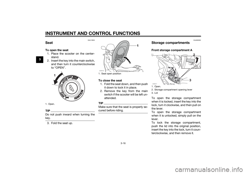
SeatTo open the seat
1. Place the scooter on the center-
stand.
2. Insert the key into the main switch,
and then turn it counterclockwise
to “OPEN”.TIPDo not push inward when turning the
key.3. Fold the seat up.To close the seat
1. Fold the seat down, and then push
it down to lock it in place.
2. Remove the key from the main
switch if the scooter will be left un-
attended.
TIPMake sure that the seat is properly se-
cured before riding.
EAUM3002
Storage compartmentsFront storage compartment A
To open the storage compartment
when it is locked, insert the key into the
lock, turn it clockwise, and then pull on
the lever.
To open the storage compartment
when it is unlocked, simply pull on the
lever.
To lock the storage compartment,
push the lid into the original position,
insert the key into the lock, turn it coun-
terclockwise, and then remove it.
1. Open.
1. Seat open positionZAUM1016
1. Open.
2. Storage compartment opening lever
3. LidZAUM1017
3
1 12
U1SDE1E0.book Page 16 Monday, September 23, 2013 3:55 PM
Page 33 of 92
INSTRUMENT AND CONTROL FUNCTIONS
3-17
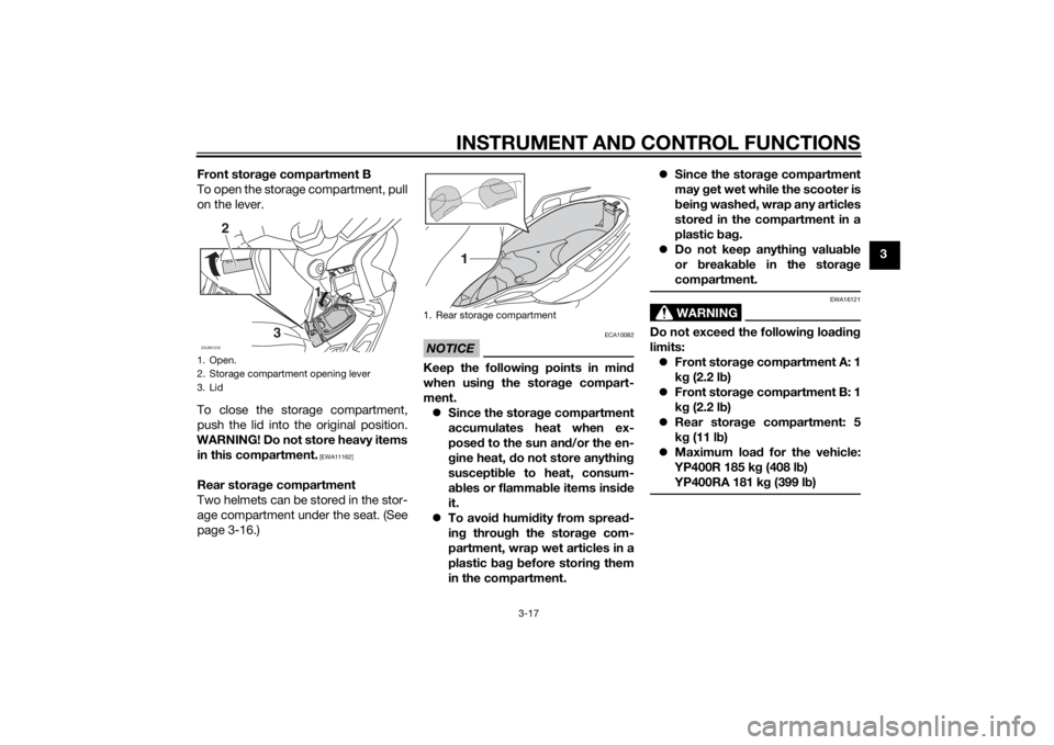
3 Front storage compartment B
To open the storage compartment, pull
on the lever.
To close the storage compartment,
push the lid into the original position.
WARNING! Do not store heavy items
in this compartment.
[EWA11162]
Rear storage compartment
Two helmets can be stored in the stor-
age compartment under the seat. (See
page 3-16.)
NOTICE
ECA10082
Keep the following points in mind
when using the storage compart-
ment.
Since the storage compartment
accumulates heat when ex-
posed to the sun and/or the en-
gine heat, do not store anything
susceptible to heat, consum-
ables or flammable items inside
it.
To avoid humidity from spread-
ing through the storage com-
partment, wrap wet articles in a
plastic bag before storing them
in the compartment.Since the storage compartment
may get wet while the scooter is
being washed, wrap any articles
stored in the compartment in a
plastic bag.
Do not keep anything valuable
or breakable in the storage
compartment.
WARNING
EWA16121
Do not exceed the following loading
limits:
Front storage compartment A: 1
kg (2.2 lb)
Front storage compartment B: 1
kg (2.2 lb)
Rear storage compartment: 5
kg (11 lb)
Maximum load for the vehicle:
YP400R 185 kg (408 lb)
YP400RA 181 kg (399 lb)
1. Open.
2. Storage compartment opening lever
3. LidZAUM1018
2
31 1
1. Rear storage compartment
U1SDE1E0.book Page 17 Monday, September 23, 2013 3:55 PM
Page 34 of 92
INSTRUMENT AND CONTROL FUNCTIONS
3-18
3
EAU14893
Adjusting the shock absorber
assemblies
WARNING
EWA10211
Always adjust both shock absorber
assemblies equally, otherwise poor
handling and loss of stability may re-
sult.Each shock absorber assembly is
equipped with a spring preload adjust-
ing ring.NOTICE
ECA10102
To avoid damaging the mechanism,
do not attempt to turn beyond the
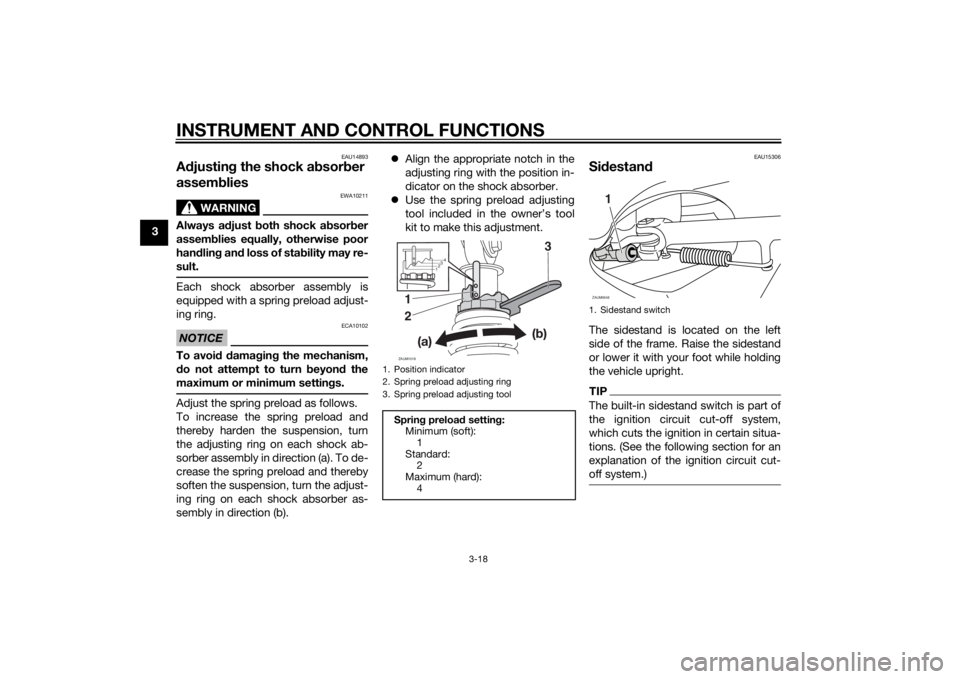
maximum or minimum settings.Adjust the spring preload as follows.
To increase the spring preload and
thereby harden the suspension, turn
the adjusting ring on each shock ab-
sorber assembly in direction (a). To de-
crease the spring preload and thereby
soften the suspension, turn the adjust-
ing ring on each shock absorber as-
sembly in direction (b).Align the appropriate notch in the
adjusting ring with the position in-
dicator on the shock absorber.
Use the spring preload adjusting
tool included in the owner’s tool
kit to make this adjustment.
EAU15306
SidestandThe sidestand is located on the left
side of the frame. Raise the sidestand
or lower it with your foot while holding
the vehicle upright.TIPThe built-in sidestand switch is part of
the ignition circuit cut-off system,
which cuts the ignition in certain situa-
tions. (See the following section for an
explanation of the ignition circuit cut-
off system.)
1. Position indicator
2. Spring preload adjusting ring
3. Spring preload adjusting toolSpring preload setting:
Minimum (soft):
1
Standard:
2
Maximum (hard):
4ZAUM1019
3
1
2
1234
1. Sidestand switchZAUM0648
1
U1SDE1E0.book Page 18 Monday, September 23, 2013 3:55 PM
Page 35 of 92

INSTRUMENT AND CONTROL FUNCTIONS
3-19
3
WARNING
EWA10242
The vehicle must not be ridden with
the sidestand down, or if the side-
stand cannot be properly moved up
(or does not stay up), otherwise the
sidestand could contact the ground
and distract the operator, resulting
in a possible loss of control.
Yamaha’s ignition circuit cut-off
system has been designed to assist
the operator in fulfilling the respon-
sibility of raising the sidestand be-
fore starting off. Therefore, check
this system regularly and have a
Yamaha dealer repair it if it does not
function properly.
EAU45053
Ignition circuit cut-off systemThe ignition circuit cut-off system
(comprising the sidestand switch and
brake light switches) has the following
functions.
It prevents starting when the side-
stand is up, but neither brake is
applied.
It prevents starting when either
brake is applied, but the sidestand
is still down.
It cuts the running engine when
the sidestand is moved down.
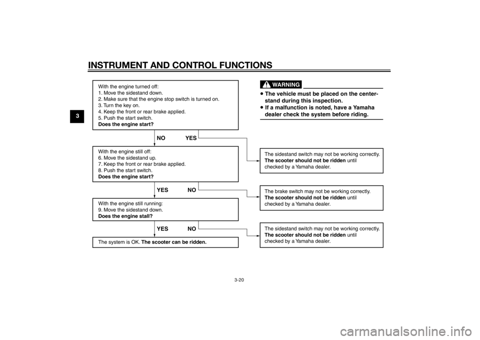
Periodically check the operation of the
ignition circuit cut-off system accord-
ing to the following procedure.
U1SDE1E0.book Page 19 Monday, September 23, 2013 3:55 PM
Page 36 of 92
INSTRUMENT AND CONTROL FUNCTIONS
3-20
3
With the engine turned off:
1. Move the sidestand down.
2. Make sure that the engine stop switch is turned on.
3. Turn the key on.
4. Keep the front or rear brake applied.
5. Push the start switch.
Does the engine start?
With the engine still off:
6. Move the sidestand up.
7. Keep the front or rear brake applied.
8. Push the start switch.
Does the engine start?
With the engine still running:
9. Move the sidestand down.
Does the engine stall?
The system is OK. The scooter can be ridden.The sidestand switch may not be working correctly.
The scooter should not be ridden until
checked by a Yamaha dealer.
The sidestand switch may not be working correctly.
The scooter should not be ridden until
checked by a Yamaha dealer.
YES NO YES NO NO YES
The brake switch may not be working correctly.
The scooter should not be ridden until
checked by a Yamaha dealer.• The vehicle must be placed on the center-
stand during this inspection.• If a malfunction is noted, have a Yamaha
dealer check the system before riding.
WARNING
U1SDE1E0.book Page 20 Monday, September 23, 2013 3:55 PM
Page 37 of 92
FOR YOUR SAFETY – PRE-OPERATION CHECKS
4-1
4
EAU15598
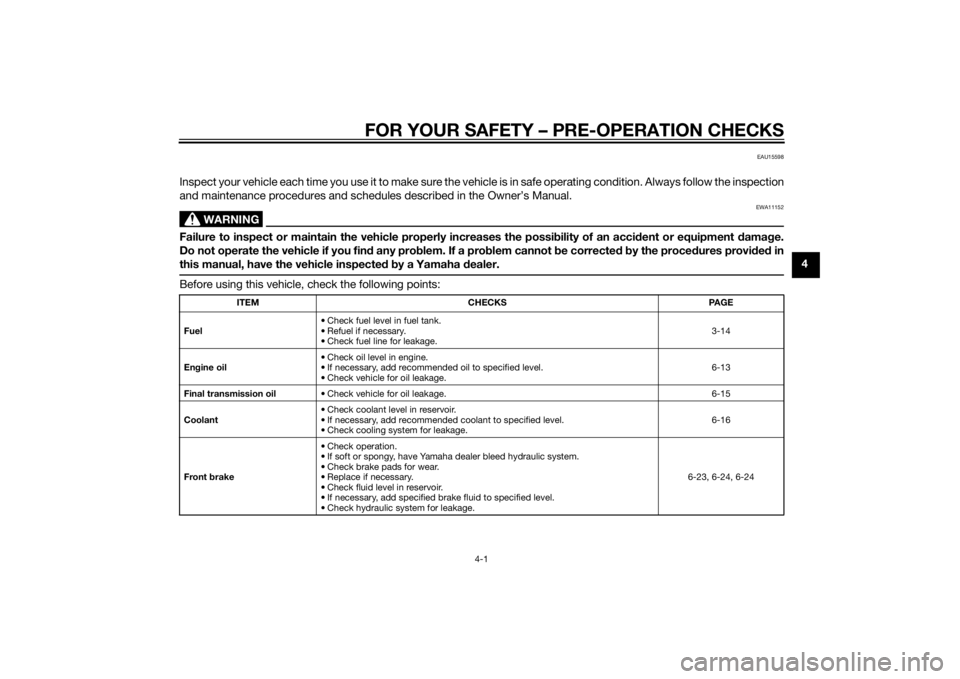
Inspect your vehicle each time you use it to make sure the vehicle is in safe operating condition. Always follow the inspection
and maintenance procedures and schedules described in the Owner’s Manual.
WARNING
EWA11152
Failure to inspect or maintain the vehicle properly increases the possibility of an accident or equipment damage.
Do not operate the vehicle if you find any problem. If a problem cannot be corrected by the procedures provided in
this manual, have the vehicle inspected by a Yamaha dealer.Before using this vehicle, check the following points:
ITEM CHECKS PAGE
Fuel• Check fuel level in fuel tank.
• Refuel if necessary.
• Check fuel line for leakage.3-14
Engine oil• Check oil level in engine.
• If necessary, add recommended oil to specified level.
• Check vehicle for oil leakage.6-13
Final transmission oil• Check vehicle for oil leakage. 6-15
Coolant• Check coolant level in reservoir.
• If necessary, add recommended coolant to specified level.
• Check cooling system for leakage.6-16
Front brake• Check operation.
• If soft or spongy, have Yamaha dealer bleed hydraulic system.
• Check brake pads for wear.
• Replace if necessary.
• Check fluid level in reservoir.
• If necessary, add specified brake fluid to specified level.
• Check hydraulic system for leakage.6-23, 6-24, 6-24
U1SDE1E0.book Page 1 Monday, September 23, 2013 3:55 PM
Page 38 of 92

FOR YOUR SAFETY – PRE-OPERATION CHECKS
4-2
4
Rear brake• Check operation.
• If soft or spongy, have Yamaha dealer bleed hydraulic system.
• Check brake pads for wear.
• Replace if necessary.
• Check fluid level in reservoir.
• If necessary, add specified brake fluid to specified level.
• Check hydraulic system for leakage.6-23, 6-24, 6-24
Throttle grip• Make sure that operation is smooth.
• Check throttle grip free play.
• If necessary, have Yamaha dealer adjust throttle grip free play and lubricate ca-
ble and grip housing.6-20, 6-26
Wheels and tires•Check for damage.
• Check tire condition and tread depth.
• Check air pressure.
• Correct if necessary.6-21, 6-22
Brake levers• Make sure that operation is smooth.
• Lubricate lever pivoting points if necessary.6-27
Centerstand, sidestand• Make sure that operation is smooth.
• Lubricate pivots if necessary.6-27
Chassis fasteners• Make sure that all nuts, bolts and screws are properly tightened.
• Tighten if necessary.—
Instruments, lights, signals
and switches• Check operation.
• Correct if necessary.—
Sidestand switch • Check operation of ignition circuit cut-off system.
• If system is not working correctly, have Yamaha dealer check vehicle.3-18 ITEM CHECKS PAGE
U1SDE1E0.book Page 2 Monday, September 23, 2013 3:55 PM
Page 39 of 92
OPERATION AND IMPORTANT RIDING POINTS
5-1
5
EAU15952
Read the Owner’s Manual carefully to
become familiar with all controls. If
there is a control or function you do not
understand, ask your Yamaha dealer.
WARNING
EWA10272
Failure to familiarize yourself with
the controls can lead to loss of con-
trol, which could cause an accident
or injury.
EAU48021
TIPThis model is equipped with a lean an-
gle sensor to stop the engine in case of
a turnover. In this case, the multi-func-
tion display indicates error code 30,
but this is not a malfunction. Turn the
the error code. Failing to do so will pre-
vent the engine from starting even
though the engine will crank when
pushing the start switch.
EAUS1893
Starting the engineNOTICE
ECA10251
See page 5-4 for engine break-in in-
structions prior to operating the ve-
hicle for the first time.In order for the ignition circuit cut-off
system to enable starting, the side-
stand must be up.
See page 3-19 for more information.
1. Turn the key to “ON”.
The following warning light, indi-
cator light and indicators should
come on for a few seconds, then
go off.
Engine trouble warning light
ABS warning light (for ABS
models)
Immobilizer system indicator
light
V-belt replacement indicator
Oil change indicator
U1SDE1E0.book Page 1 Monday, September 23, 2013 3:55 PM
Page 40 of 92
OPERATION AND IMPORTANT RIDING POINTS
5-2
5
NOTICE
ECA15025
If a warning light, indicator light or
indicator does not go off, see pages
3-3, 3-6, 3-8, 3-8 or 3-8 for the corre-
sponding warning light, indicator
light or indicator circuit check.2. Close the throttle completely.
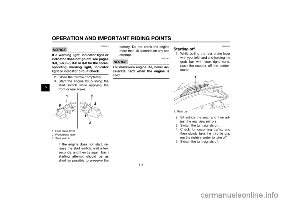
3. Start the engine by pushing the
start switch while applying the
front or rear brake.
If the engine does not start, re-
lease the start switch, wait a few
seconds, and then try again. Each
starting attempt should be as
short as possible to preserve thebattery. Do not crank the engine
more than 10 seconds on any one
attempt.
NOTICE
ECA11043
For maximum engine life, never ac-
celerate hard when the engine is
cold!
EAU45093
Starting off1. While pulling the rear brake lever
with your left hand and holding the
grab bar with your right hand,
push the scooter off the center-
stand.
2. Sit astride the seat, and then ad-
just the rear view mirrors.
3. Switch the turn signals on.
4. Check for oncoming traffic, and
then slowly turn the throttle grip
(on the right) in order to take off.
5. Switch the turn signals off.
1. Rear brake lever
2. Front brake lever
3. Start switch
1. Grab bar
U1SDE1E0.book Page 2 Monday, September 23, 2013 3:55 PM