YAMAHA YZ125LC 2012 Owners Manual
Manufacturer: YAMAHA, Model Year: 2012, Model line: YZ125LC, Model: YAMAHA YZ125LC 2012Pages: 168, PDF Size: 8.27 MB
Page 91 of 168
4-29
YPVS GOVERNOR
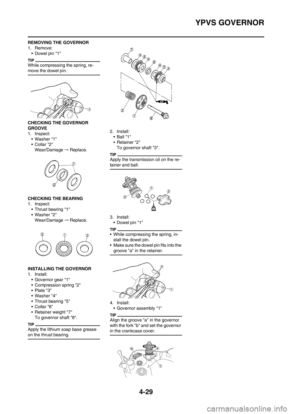
REMOVING THE GOVERNOR
1. Remove:
• Dowel pin "1"
While compressing the spring, re-
move the dowel pin.
CHECKING THE GOVERNOR
GROOVE
1. Inspect:
• Washer "1"
•Collar "2"
Wear/Damage→Replace.
CHECKING THE BEARING
1. Inspect:
• Thrust bearing "1"
• Washer "2"
Wear/Damage→Replace.
INSTALLING THE GOVERNOR
1. Install:
• Governor gear "1"
• Compression spring "2"
• Plate "3"
• Washer "4"
• Thrust bearing "5"
•Collar "6"
• Retainer weight "7"
To governor shaft "8".
Apply the lithium soap base grease
on the thrust bearing.
2. Install:
• Ball "1"
• Retainer "2"
To governor shaft "3".
Apply the transmission oil on the re-
tainer and ball.
3. Install:
• Dowel pin "1"
• While compressing the spring, in-
stall the dowel pin.
• Make sure the dowel pin fits into the
groove "a" in the retainer.
4. Install:
• Governor assembly "1"
Align the groove "a" in the governor
with the fork "b" and set the governor
in the crankcase cover.
Page 92 of 168
4-30
WATER PUMP
WATER PUMP
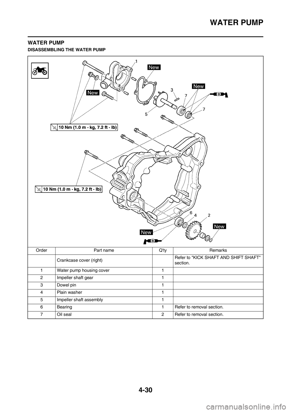
DISASSEMBLING THE WATER PUMP
Order Part name Q'ty Remarks
Crankcase cover (right)Refer to "KICK SHAFT AND SHIFT SHAFT"
section.
1 Water pump housing cover 1
2 Impeller shaft gear 1
3 Dowel pin 1
4 Plain washer 1
5 Impeller shaft assembly 1
6 Bearing 1 Refer to removal section.
7 Oil seal 2 Refer to removal section.
Page 93 of 168
4-31
WATER PUMP
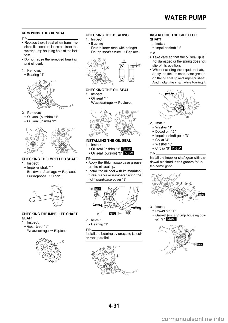
REMOVING THE OIL SEAL
• Replace the oil seal when transmis-
sion oil or coolant leaks out from the
water pump housing hole at the bot-
tom.
• Do not reuse the removed bearing
and oil seal.
1. Remove:
• Bearing "1"
2. Remove:
• Oil seal (outside) "1"
• Oil seal (inside) "2"
CHECKING THE IMPELLER SHAFT
1. Inspect:
• Impeller shaft "1"
Bend/wear/damage→Replace.
Fur deposits→Clean.
CHECKING THE IMPELLER SHAFT
GEAR
1. Inspect:
• Gear teeth "a"
Wear/damage→Replace.CHECKING THE BEARING
1. Inspect:
•Bearing
Rotate inner race with a finger.
Rough spot/seizure→Replace.
CHECKING THE OIL SEAL
1. Inspect:
• Oil seal "1"
Wear/damage→Replace.
INSTALLING THE OIL SEAL
1. Install:
• Oil seal (inside) "1"
• Oil seal (outside) "2"
• Apply the lithium soap base grease
on the oil seal lip.
• Install the oil seal with its manufac-
ture's marks or numbers facing the
right crankcase cover "3".
2. Install:
•Bearing "1"
Install the bearing by pressing its out-
er race parallel.
INSTALLING THE IMPELLER
SHAFT
1. Install:
• Impeller shaft "1"
• Take care so that the oil seal lip is
not damaged or the spring does not
slip off its position.
• When installing the impeller shaft,
apply the lithium soap base grease
on the oil seal lip and impeller shaft.
And install the shaft while turning it.
2. Install:
• Washer "1"
• Dowel pin "2"
• Impeller shaft gear "3"
•Collar "4"
• Washer "5"
• Circlip "6"
Install the Impeller shaft gear with the
dowel pin fitted in the groove "a" in
the same gear.
3. Install:
• Dowel pin "1"
• Gasket (water pump housing cov-
er) "2"
Page 94 of 168
4-32
WATER PUMP
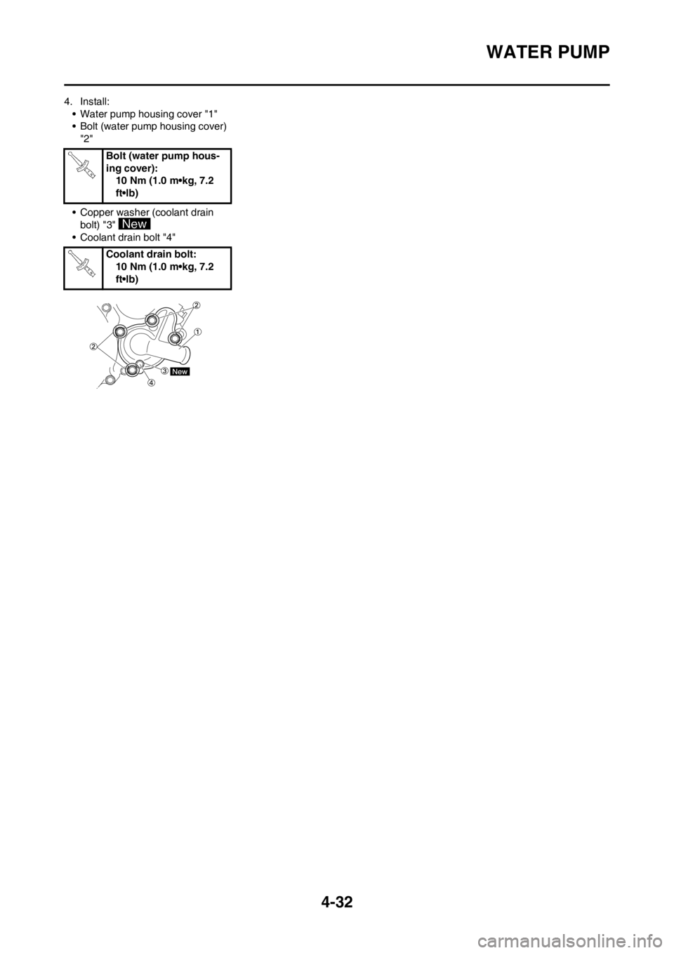
4. Install:
• Water pump housing cover "1"
• Bolt (water pump housing cover)
"2"
• Copper washer (coolant drain
bolt) "3"
• Coolant drain bolt "4" Bolt (water pump hous-
ing cover):
10 Nm (1.0 m•kg, 7.2
ft•lb)
Coolant drain bolt:
10 Nm (1.0 m•kg, 7.2
ft•lb)
Page 95 of 168
4-33
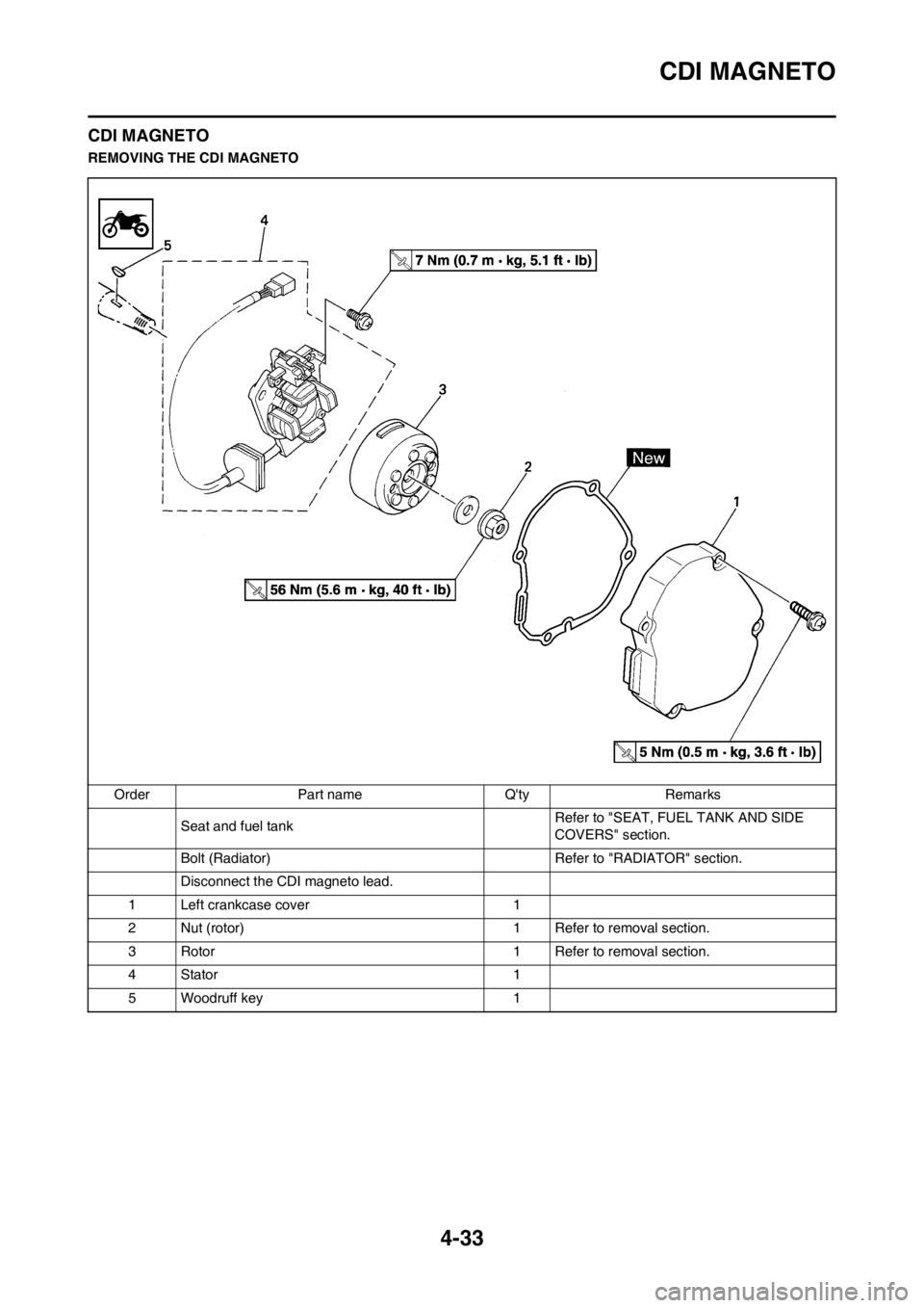
CDI MAGNETO
CDI MAGNETO
REMOVING THE CDI MAGNETO
Order Part name Q'ty Remarks
Seat and fuel tankRefer to "SEAT, FUEL TANK AND SIDE
COVERS" section.
Bolt (Radiator) Refer to "RADIATOR" section.
Disconnect the CDI magneto lead.
1 Left crankcase cover 1
2 Nut (rotor) 1 Refer to removal section.
3 Rotor 1 Refer to removal section.
4 Stator 1
5 Woodruff key 1
Page 96 of 168
4-34
CDI MAGNETO
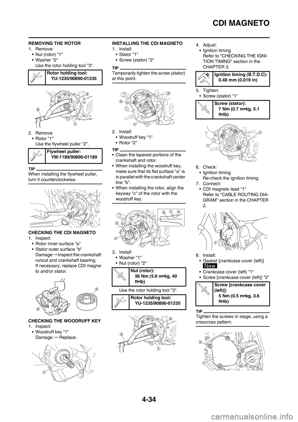
REMOVING THE ROTOR
1. Remove:
• Nut (rotor) "1"
• Washer "2"
Use the rotor holding tool "3".
2. Remove:
• Rotor "1"
Use the flywheel puller "2".
When installing the flywheel puller,
turn it counterclockwise.
CHECKING THE CDI MAGNETO
1. Inspect:
• Rotor inner surface "a"
• Stator outer surface "b"
Damage→Inspect the crankshaft
runout and crankshaft bearing.
If necessary, replace CDI magne-
to and/or stator.
CHECKING THE WOODRUFF KEY
1. Inspect:
• Woodruff key "1"
Damage→Replace.INSTALLING THE CDI MAGNETO
1. Install:
• Stator "1"
• Screw (stator) "2"
Temporarily tighten the screw (stator)
at this point.
2. Install:
• Woodruff key "1"
• Rotor "2"
• Clean the tapered portions of the
crankshaft and rotor.
• When installing the woodruff key,
make sure that its flat surface "a" is
in parallel with the crankshaft center
line "b".
• When installing the rotor, align the
keyway "c" of the rotor with the
woodruff key.
3. Install:
• Washer "1"
• Nut (rotor) "2"
Use the rotor holding tool "3".4. Adjust:
• Ignition timing
Refer to "CHECKING THE IGNI-
TION TIMING" section in the
CHAPTER 3.
5. Tighten:
• Screw (stator) "1"
6. Check:
• Ignition timing
Re-check the ignition timing.
7. Connect:
• CDI magneto lead "1"
Refer to "CABLE ROUTING DIA-
GRAM" section in the CHAPTER
2.
8. Install:
• Gasket [crankcase cover (left)]
• Crankcase cover (left) "1"
• Screw [crankcase cover (left)] "2"
Tighten the screws in stage, using a
crisscross pattern.
Rotor holding tool:
YU-1235/90890-01235
Flywheel puller:
YM-1189/90890-01189
Nut (rotor):
56 Nm (5.6 m•kg, 40
ft•lb)
Rotor holding tool:
YU-1235/90890-01235
Ignition timing (B.T.D.C):
0.48 mm (0.019 in)
Screw (stator):
7 Nm (0.7 m•kg, 5.1
ft•lb)
Screw [crankcase cover
(left)]:
5 Nm (0.5 m•kg, 3.6
ft•lb)
Page 97 of 168
4-35
ENGINE REMOVAL
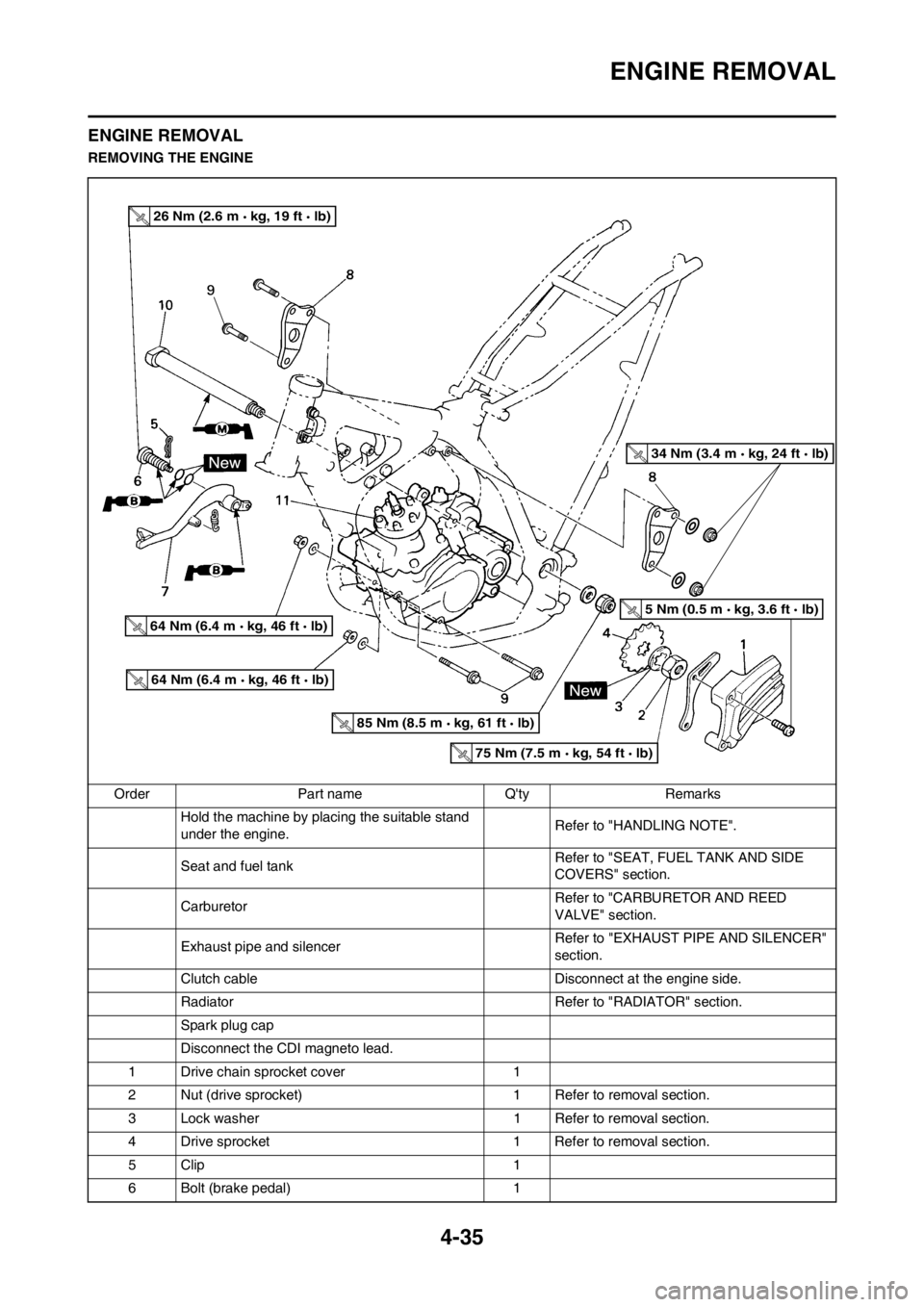
ENGINE REMOVAL
REMOVING THE ENGINE
Order Part name Q'ty Remarks
Hold the machine by placing the suitable stand
under the engine.Refer to "HANDLING NOTE".
Seat and fuel tank Refer to "SEAT, FUEL TANK AND SIDE
COVERS" section.
Carburetor Refer to "CARBURETOR AND REED
VALVE" section.
Exhaust pipe and silencer Refer to "EXHAUST PIPE AND SILENCER"
section.
Clutch cable Disconnect at the engine side.
Radiator Refer to "RADIATOR" section.
Spark plug cap
Disconnect the CDI magneto lead.
1 Drive chain sprocket cover 1
2 Nut (drive sprocket) 1 Refer to removal section.
3 Lock washer 1 Refer to removal section.
4 Drive sprocket 1 Refer to removal section.
5Clip 1
6 Bolt (brake pedal) 1
26 Nm (2.6 m kg, 19 ft lb)
64 Nm (6.4 m kg, 46 ft lb)
64 Nm (6.4 m kg, 46 ft lb)
85 Nm (8.5 m kg, 61 ft lb)
75 Nm (7.5 m kg, 54 ft lb)
5 Nm (0.5 m kg, 3.6 ft lb)
34 Nm (3.4 m kg, 24 ft lb)
Page 98 of 168
4-36
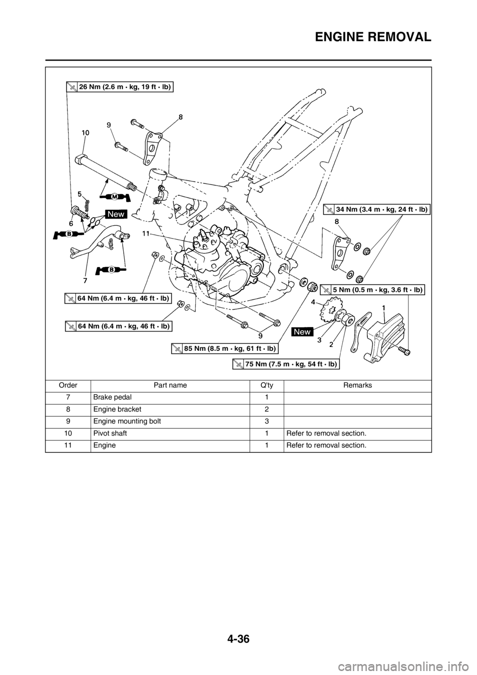
ENGINE REMOVAL
7 Brake pedal 1
8 Engine bracket 2
9 Engine mounting bolt 3
10 Pivot shaft 1 Refer to removal section.
11 Engine 1 Refer to removal section. Order Part name Q'ty Remarks
26 Nm (2.6 m kg, 19 ft lb)
64 Nm (6.4 m kg, 46 ft lb)
64 Nm (6.4 m kg, 46 ft lb)
85 Nm (8.5 m kg, 61 ft lb)
75 Nm (7.5 m kg, 54 ft lb)
5 Nm (0.5 m kg, 3.6 ft lb)
34 Nm (3.4 m kg, 24 ft lb)
Page 99 of 168
4-37
ENGINE REMOVAL
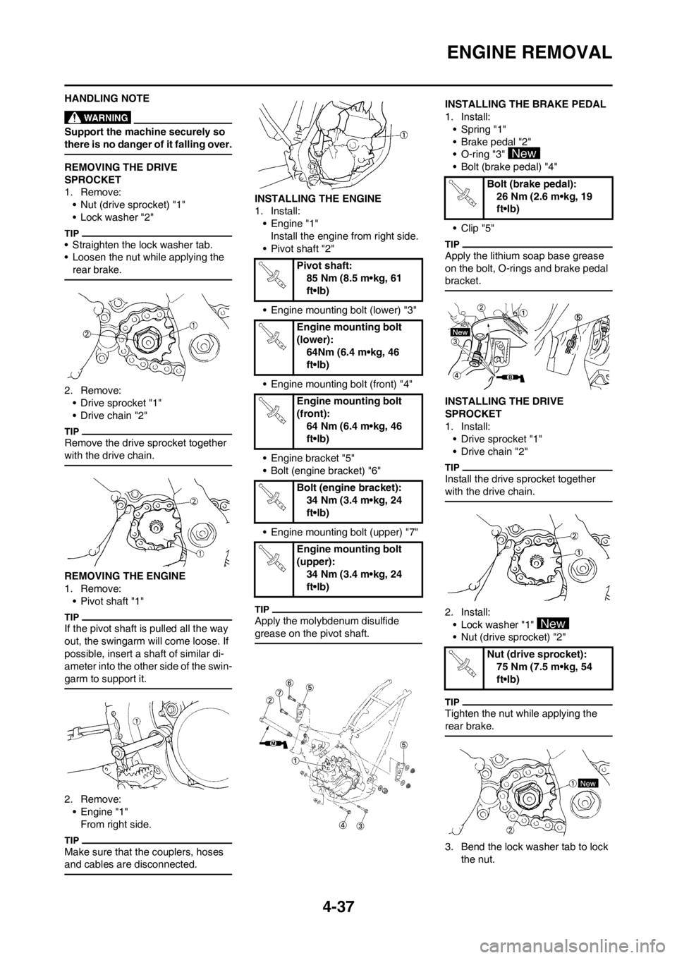
HANDLING NOTE
Support the machine securely so
there is no danger of it falling over.
REMOVING THE DRIVE
SPROCKET
1. Remove:
• Nut (drive sprocket) "1"
• Lock washer "2"
• Straighten the lock washer tab.
• Loosen the nut while applying the
rear brake.
2. Remove:
• Drive sprocket "1"
• Drive chain "2"
Remove the drive sprocket together
with the drive chain.
REMOVING THE ENGINE
1. Remove:
• Pivot shaft "1"
If the pivot shaft is pulled all the way
out, the swingarm will come loose. If
possible, insert a shaft of similar di-
ameter into the other side of the swin-
garm to support it.
2. Remove:
• Engine "1"
From right side.
Make sure that the couplers, hoses
and cables are disconnected.
INSTALLING THE ENGINE
1. Install:
• Engine "1"
Install the engine from right side.
• Pivot shaft "2"
• Engine mounting bolt (lower) "3"
• Engine mounting bolt (front) "4"
• Engine bracket "5"
• Bolt (engine bracket) "6"
• Engine mounting bolt (upper) "7"
Apply the molybdenum disulfide
grease on the pivot shaft.
INSTALLING THE BRAKE PEDAL
1. Install:
• Spring "1"
• Brake pedal "2"
• O-ring "3"
• Bolt (brake pedal) "4"
• Clip "5"
Apply the lithium soap base grease
on the bolt, O-rings and brake pedal
bracket.
INSTALLING THE DRIVE
SPROCKET
1. Install:
• Drive sprocket "1"
• Drive chain "2"
Install the drive sprocket together
with the drive chain.
2. Install:
• Lock washer "1"
• Nut (drive sprocket) "2"
Tighten the nut while applying the
rear brake.
3. Bend the lock washer tab to lock
the nut.
Pivot shaft:
85 Nm (8.5 m•kg, 61
ft•lb)
Engine mounting bolt
(lower):
64Nm (6.4 m•kg, 46
ft•lb)
Engine mounting bolt
(front):
64 Nm (6.4 m•kg, 46
ft•lb)
Bolt (engine bracket):
34 Nm (3.4 m•kg, 24
ft•lb)
Engine mounting bolt
(upper):
34 Nm (3.4 m•kg, 24
ft•lb)
Bolt (brake pedal):
26 Nm (2.6 m•kg, 19
ft•lb)
Nut (drive sprocket):
75 Nm (7.5 m•kg, 54
ft•lb)
Page 100 of 168
4-38
ENGINE REMOVAL
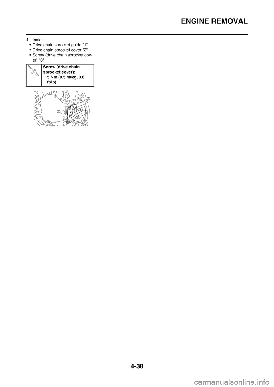
4. Install:
• Drive chain sprocket guide "1"
• Drive chain sprocket cover "2"
• Screw (drive chain sprocket cov-
er) "3"
Screw (drive chain
sprocket cover):
5 Nm (0.5 m•kg, 3.6
ft•lb)