YAMAHA YZ125LC 2013 Manual PDF
Manufacturer: YAMAHA, Model Year: 2013, Model line: YZ125LC, Model: YAMAHA YZ125LC 2013Pages: 168, PDF Size: 8.19 MB
Page 71 of 168
4-9
CARBURETOR AND REED VALVE
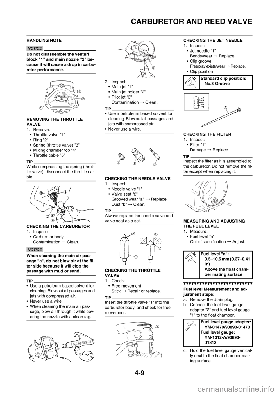
HANDLING NOTE
Do not disassemble the venturi
block "1" and main nozzle "2" be-
cause it will cause a drop in carbu-
retor performance.
REMOVING THE THROTTLE
VALVE
1. Remove:
• Throttle valve "1"
• Ring "2"
• Spring (throttle valve) "3"
• Mixing chamber top "4"
• Throttle cable "5"
While compressing the spring (throt-
tle valve), disconnect the throttle ca-
ble.
CHECKING THE CARBURETOR
1. Inspect:
• Carburetor body
Contamination → Clean.
When cleaning the main air pas-
sage "a", do not blow air at the fil-
ter side because it will clog the
passage with mud or sand.
• Use a petroleum based solvent for
cleaning. Blow out all passages and
jets with compressed air.
• Never use a wire.
• When cleaning the main air pas-
sage, blow air through it while cov-
ering the nozzle with a clean rag.
2. Inspect:
•Main jet "1"
• Main jet holder "2"
• Pilot jet "3"
Contamination → Clean.
• Use a petroleum based solvent for
cleaning. Blow out all passages and
jets with compressed air.
• Never use a wire.
CHECKING THE NEEDLE VALVE
1. Inspect:
• Needle valve "1"
• Valve seat "2"
Grooved wear "a" → Replace.
Dust "b" → Clean.
Always replace the needle valve and
valve seat as a set.
CHECKING THE THROTTLE
VALVE
1. Check:
• Free movement
Stick → Repair or replace.
Insert the throttle valve "1" into the
carburetor body, and check for free
movement.
CHECKING THE JET NEEDLE
1. Inspect:
• Jet needle "1"
Bends/wear → Replace.
• Clip groove
Free play exists/wear → R e p l a c e .
• Clip position
CHECKING THE FILTER
1. Inspect:
•Filter "1"
Damage → Replace.
Inspect the filter as it is assembled to
the carburetor. Do not remove the fil-
ter except when replacing it.
MEASURING AND ADJUSTING
THE FUEL LEVEL
1. Measure:
• Fuel level "a"
Out of specification → Adjust.
Fuel level Measurement and ad-
justment steps:
a. Remove the drain plug.
b. Connect the fuel level gauge
adapter "2" and fuel level gauge
"1" to the float chamber.
c. Hold the fuel level gauge vertical-
ly next to the float chamber mat-
ing surface.
Standard clip position:
No.3 Groove
Fuel level "a":
9.5–10.5 mm (0.37–0.41
in)
Above the float cham-
ber mating surface
Fuel level gauge adapter:
YM-01470/90890-01470
Fuel level gauge:
YM-1312-A/90890-
01312
Page 72 of 168
4-10
CARBURETOR AND REED VALVE
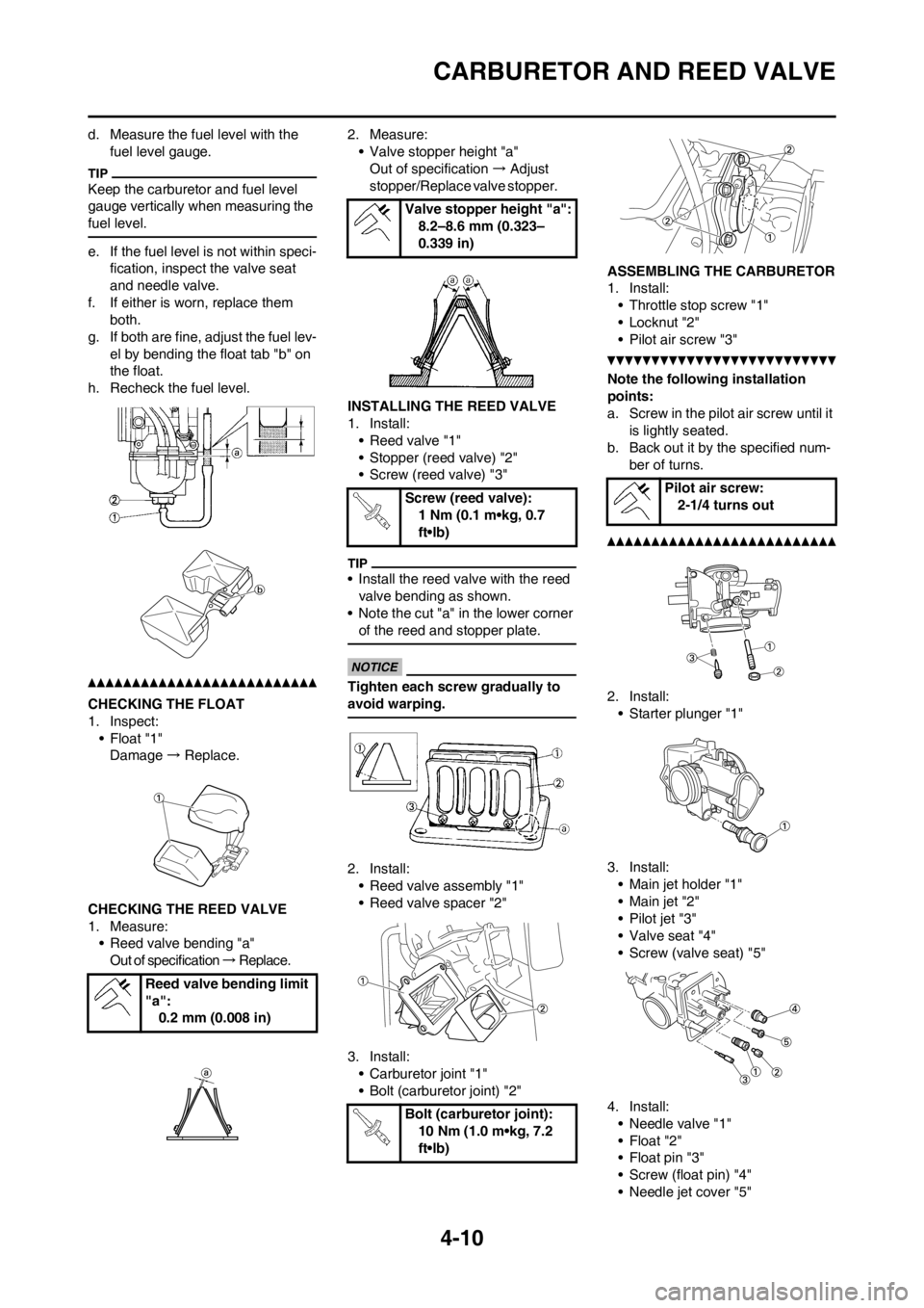
d. Measure the fuel level with the
fuel level gauge.
Keep the carburetor and fuel level
gauge vertically when measuring the
fuel level.
e. If the fuel level is not within speci-
fication, inspect the valve seat
and needle valve.
f. If either is worn, replace them
both.
g. If both are fine, adjust the fuel lev-
el by bending the float tab "b" on
the float.
h. Recheck the fuel level.
CHECKING THE FLOAT
1. Inspect:
• Float "1"
Damage → Replace.
CHECKING THE REED VALVE
1. Measure:
• Reed valve bending "a"
Out of specification → R e p l a c e . 2. Measure:
• Valve stopper height "a"
Out of specification → Adjust
stopper/Replace valve stopper.
INSTALLING THE REED VALVE
1. Install:
• Reed valve "1"
• Stopper (reed valve) "2"
• Screw (reed valve) "3"
• Install the reed valve with the reed
valve bending as shown.
• Note the cut "a" in the lower corner
of the reed and stopper plate.
Tighten each screw gradually to
avoid warping.
2. Install:
• Reed valve assembly "1"
• Reed valve spacer "2"
3. Install:
• Carburetor joint "1"
• Bolt (carburetor joint) "2"ASSEMBLING THE CARBURETOR
1. Install:
• Throttle stop screw "1"
• Locknut "2"
• Pilot air screw "3"
Note the following installation
points:
a. Screw in the pilot air screw until it
is lightly seated.
b. Back out it by the specified num-
ber of turns.
2. Install:
• Starter plunger "1"
3. Install:
• Main jet holder "1"
•Main jet "2"
• Pilot jet "3"
• Valve seat "4"
• Screw (valve seat) "5"
4. Install:
• Needle valve "1"
• Float "2"
• Float pin "3"
• Screw (float pin) "4"
• Needle jet cover "5" Reed valve bending limit
"a":
0.2 mm (0.008 in)
Valve stopper height "a":
8.2–8.6 mm (0.323–
0.339 in)
Screw (reed valve):
1 Nm (0.1 m•kg, 0.7
ft•lb)
Bolt (carburetor joint):
10 Nm (1.0 m•kg, 7.2
ft•lb)
Pilot air screw:
2-1/4 turns out
Page 73 of 168
4-11
CARBURETOR AND REED VALVE
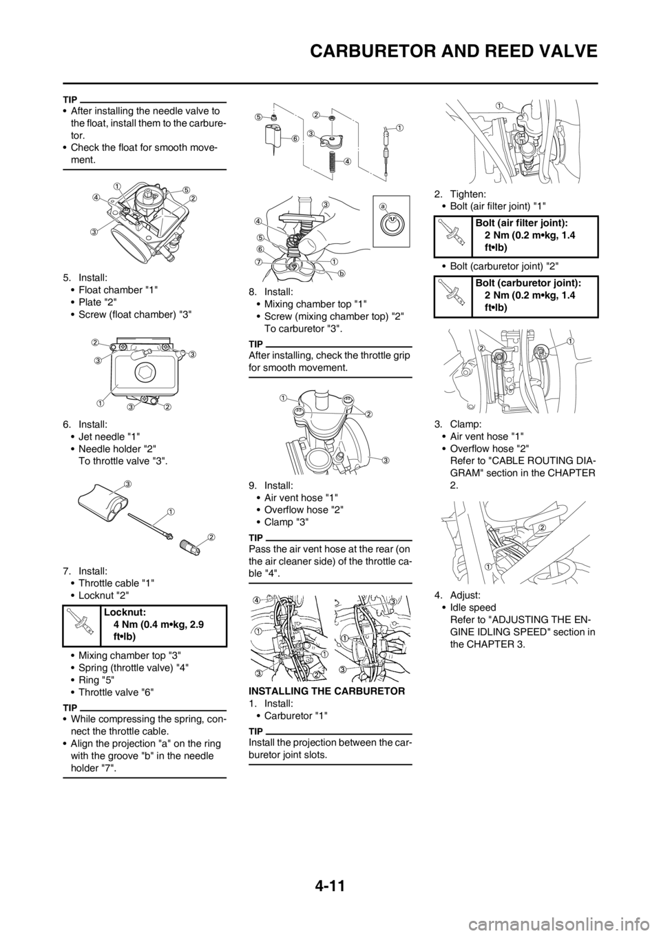
• After installing the needle valve to
the float, install them to the carbure-
tor.
• Check the float for smooth move-
ment.
5. Install:
• Float chamber "1"
• Plate "2"
• Screw (float chamber) "3"
6. Install:
• Jet needle "1"
• Needle holder "2"
To throttle valve "3".
7. Install:
• Throttle cable "1"
• Locknut "2"
• Mixing chamber top "3"
• Spring (throttle valve) "4"
• Ring "5"
• Throttle valve "6"
• While compressing the spring, con-
nect the throttle cable.
• Align the projection "a" on the ring
with the groove "b" in the needle
holder "7".
8. Install:
• Mixing chamber top "1"
• Screw (mixing chamber top) "2"
To carburetor "3".
After installing, check the throttle grip
for smooth movement.
9. Install:
• Air vent hose "1"
• Overflow hose "2"
•Clamp "3"
Pass the air vent hose at the rear (on
the air cleaner side) of the throttle ca-
ble "4".
INSTALLING THE CARBURETOR
1. Install:
• Carburetor "1"
Install the projection between the car-
buretor joint slots.
2. Tighten:
• Bolt (air filter joint) "1"
• Bolt (carburetor joint) "2"
3. Clamp:
• Air vent hose "1"
• Overflow hose "2"
Refer to "CABLE ROUTING DIA-
GRAM" section in the CHAPTER
2.
4. Adjust:
• Idle speed
Refer to "ADJUSTING THE EN-
GINE IDLING SPEED" section in
the CHAPTER 3. Locknut:
4 Nm (0.4 m•kg, 2.9
ft•lb)
Bolt (air filter joint):
2 Nm (0.2 m•kg, 1.4
ft•lb)
Bolt (carburetor joint):
2 Nm (0.2 m•kg, 1.4
ft•lb)
Page 74 of 168
4-12
CYLINDER HEAD, CYLINDER AND PISTON
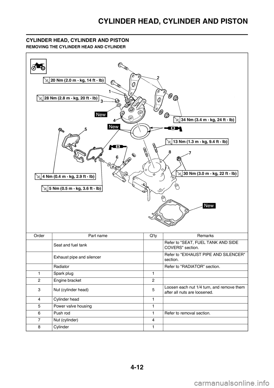
CYLINDER HEAD, CYLINDER AND PISTON
REMOVING THE CYLINDER HEAD AND CYLINDER
Order Part name Q'ty Remarks
Seat and fuel tank Refer to "SEAT, FUEL TANK AND SIDE
COVERS" section.
Exhaust pipe and silencerRefer to "EXHAUST PIPE AND SILENCER"
section.
Radiator Refer to "RADIATOR" section.
1 Spark plug 1
2 Engine bracket 2
3 Nut (cylinder head) 5Loosen each nut 1/4 turn, and remove them
after all nuts are loosened.
4 Cylinder head 1
5 Power valve housing 1
6 Push rod 1 Refer to removal section.
7 Nut (cylinder) 4
8 Cylinder 1
5 Nm (0.5 m kg, 3.6 ft lb)
4 Nm (0.4 m kg, 2.9 ft lb)
13 Nm (1.3 m kg, 9.4 ft lb)
28 Nm (2.8 m kg, 20 ft lb)
20 Nm (2.0 m kg, 14 ft lb)
30 Nm (3.0 m kg, 22 ft lb)
34 Nm (3.4 m kg, 24 ft lb)
Page 75 of 168
4-13
CYLINDER HEAD, CYLINDER AND PISTON
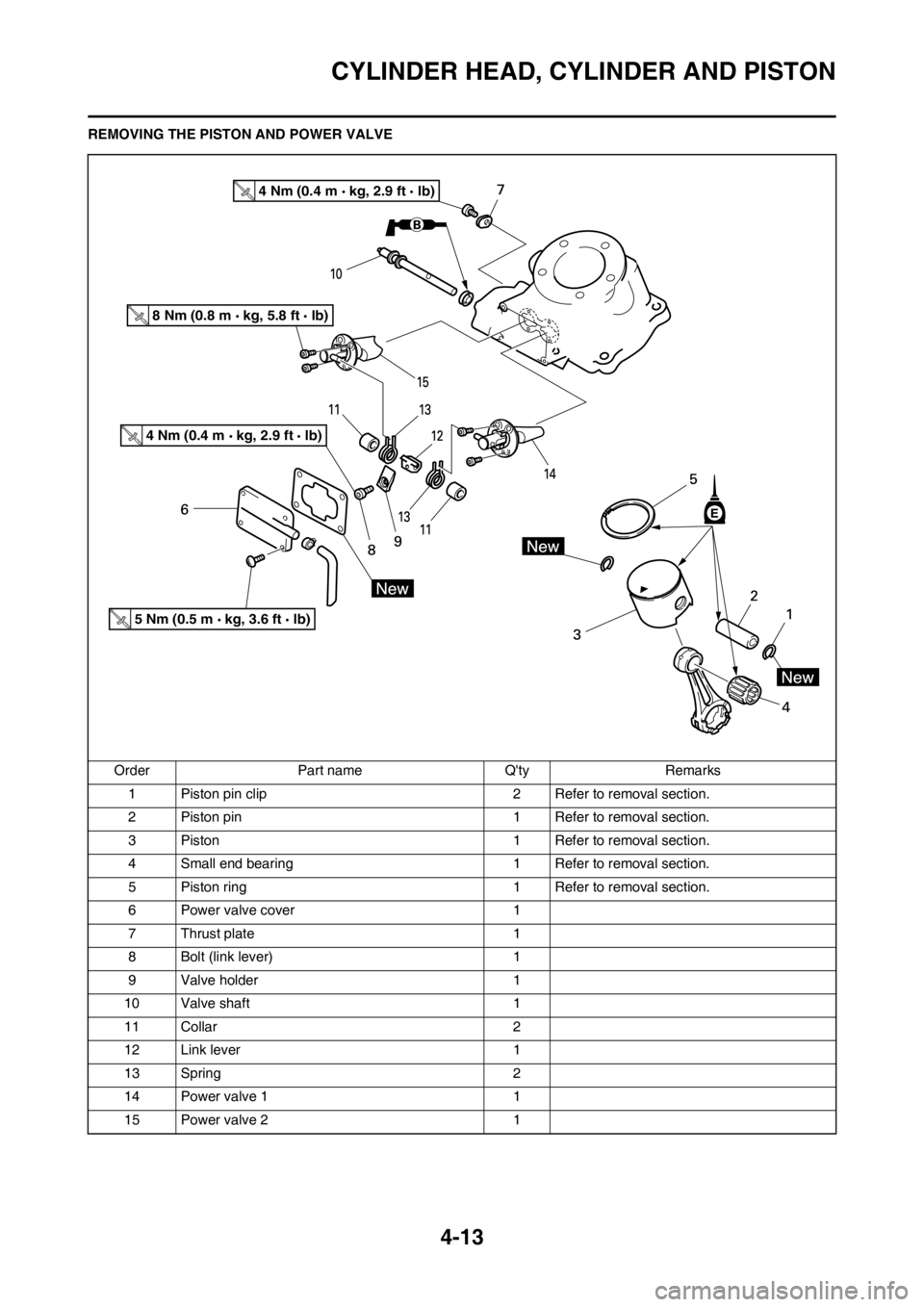
REMOVING THE PISTON AND POWER VALVE
Order Part name Q'ty Remarks
1 Piston pin clip 2 Refer to removal section.
2 Piston pin 1 Refer to removal section.
3 Piston 1 Refer to removal section.
4 Small end bearing 1 Refer to removal section.
5 Piston ring 1 Refer to removal section.
6 Power valve cover 1
7 Thrust plate 1
8 Bolt (link lever) 1
9 Valve holder 1
10 Valve shaft 1
11 Collar 2
12 Link lever 1
13 Spring 2
14 Power valve 1 1
15 Power valve 2 1
4 Nm (0.4 m kg, 2.9 ft lb)
4 Nm (0.4 m kg, 2.9 ft lb)
8 Nm (0.8 m kg, 5.8 ft lb)
5 Nm (0.5 m kg, 3.6 ft lb)
Page 76 of 168
4-14
CYLINDER HEAD, CYLINDER AND PISTON
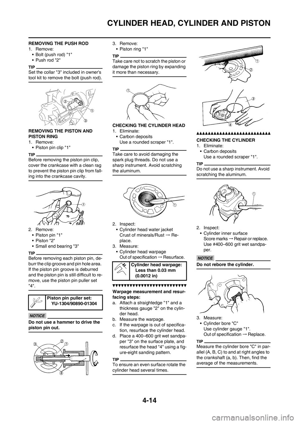
REMOVING THE PUSH ROD
1. Remove:
• Bolt (push rod) "1"
• Push rod "2"
Set the collar "3" included in owner's
tool kit to remove the bolt (push rod).
REMOVING THE PISTON AND
PISTON RING
1. Remove:
• Piston pin clip "1"
Before removing the piston pin clip,
cover the crankcase with a clean rag
to prevent the piston pin clip from fall-
ing into the crankcase cavity.
2. Remove:
• Piston pin "1"
• Piston "2"
• Small end bearing "3"
Before removing each piston pin, de-
burr the clip groove and pin hole area.
If the piston pin groove is deburred
and the piston pin is still difficult to re-
move, use the piston pin puller set
"4".
Do not use a hammer to drive the
piston pin out.
3. Remove:
• Piston ring "1"
Take care not to scratch the piston or
damage the piston ring by expanding
it more than necessary.
CHECKING THE CYLINDER HEAD
1. Eliminate:
• Carbon deposits
Use a rounded scraper "1".
Take care to avoid damaging the
spark plug threads. Do not use a
sharp instrument. Avoid scratching
the aluminum.
2. Inspect:
• Cylinder head water jacket
Crust of minerals/Rust → Re-
place.
3. Measure:
• Cylinder head warpage
Out of specification → Resurface.
Warpage measurement and resur-
facing steps:
a. Attach a straightedge "1" and a
thickness gauge "2" on the cylin-
der head.
b. Measure the warpage.
c. If the warpage is out of specifica-
tion, resurface the cylinder head.
d. Place a 400–600 grit wet sandpa-
per "3" on the surface plate, and
resurface the head "4" using a fig-
ure-eight sanding pattern.
To ensure an even surface rotate the
cylinder head several times.
CHECKING THE CYLINDER
1. Eliminate:
• Carbon deposits
Use a rounded scraper "1".
Do not use a sharp instrument. Avoid
scratching the aluminum.
2. Inspect:
• Cylinder inner surface
Score marks → Repair or replace.
Use #400–600 grit wet sandpa-
per.
Do not rebore the cylinder.
3. Measure:
• Cylinder bore "C"
Use cylinder gauge "1".
Out of specification → R e p l a c e .
Measure the cylinder bore "C" in par-
allel (A, B, C) to and at right angles to
the crankshaft (a, b). Then, find the
average of the measurements.
Piston pin puller set:
YU-1304/90890-01304
Cylinder head warpage:
Less than 0.03 mm
(0.0012 in)
Page 77 of 168
4-15
CYLINDER HEAD, CYLINDER AND PISTON
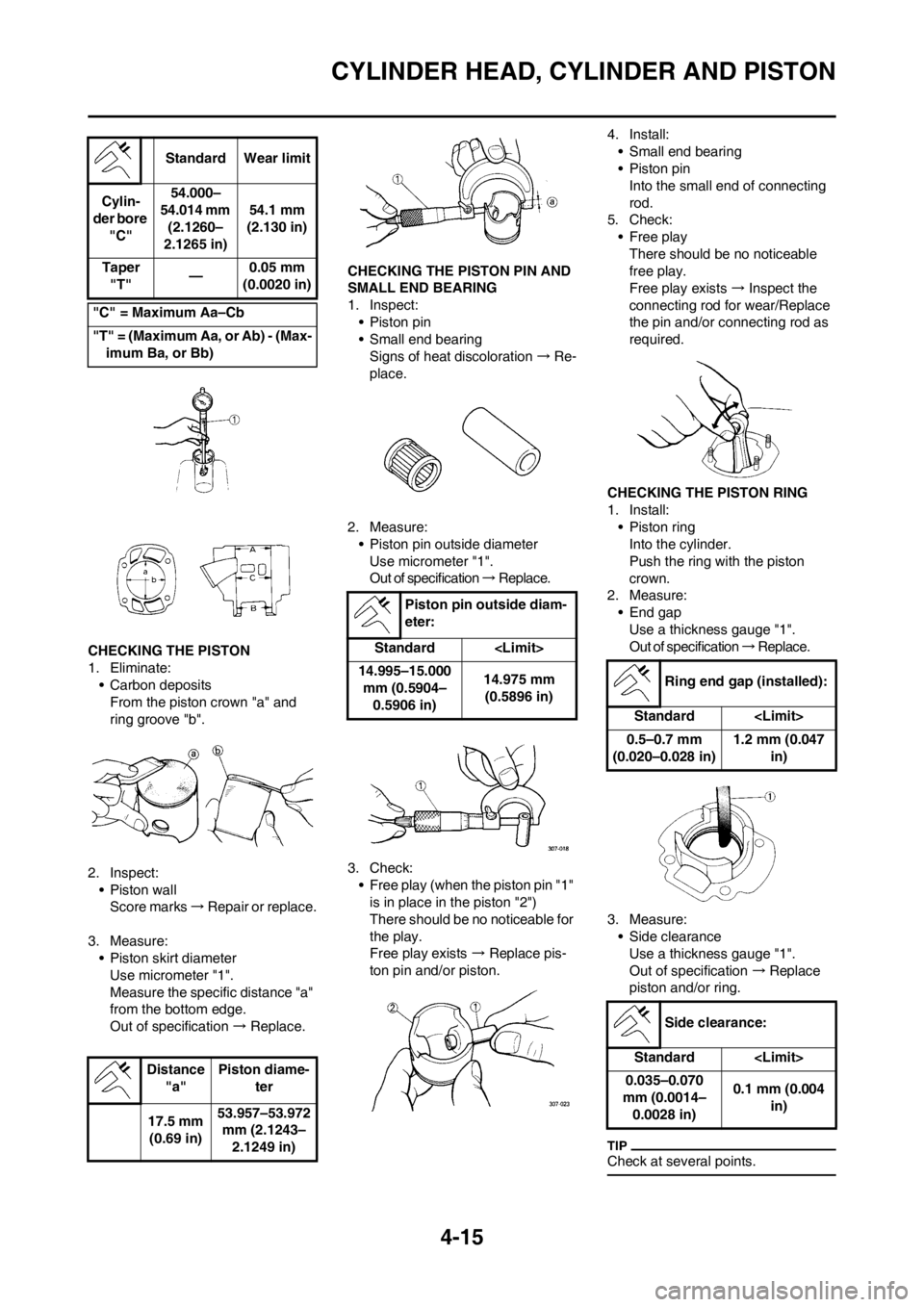
CHECKING THE PISTON
1. Eliminate:
• Carbon deposits
From the piston crown "a" and
ring groove "b".
2. Inspect:
• Piston wall
Score marks → Repair or replace.
3. Measure:
• Piston skirt diameter
Use micrometer "1".
Measure the specific distance "a"
from the bottom edge.
Out of specification → Replace.
CHECKING THE PISTON PIN AND
SMALL END BEARING
1. Inspect:
• Piston pin
• Small end bearing
Signs of heat discoloration → Re-
place.
2. Measure:
• Piston pin outside diameter
Use micrometer "1".
Out of specification → R e p l a c e .
3. Check:
• Free play (when the piston pin "1"
is in place in the piston "2")
There should be no noticeable for
the play.
Free play exists → Replace pis-
ton pin and/or piston. 4. Install:
• Small end bearing
• Piston pin
Into the small end of connecting
rod.
5. Check:
• Free play
There should be no noticeable
free play.
Free play exists → Inspect the
connecting rod for wear/Replace
the pin and/or connecting rod as
required.
CHECKING THE PISTON RING
1. Install:
• Piston ring
Into the cylinder.
Push the ring with the piston
crown.
2. Measure:
• End gap
Use a thickness gauge "1".
Out of specification → R e p l a c e .
3. Measure:
• Side clearance
Use a thickness gauge "1".
Out of specification →Replace
piston and/or ring.
Check at several points.
Standard Wear limit
Cylin-
der bore
"C"54.000–
54.014 mm
(2.1260–
2.1265 in)54.1 mm
(2.130 in)
Taper
"T"—0.05 mm
(0.0020 in)
"C" = Maximum Aa–Cb
"T" = (Maximum Aa, or Ab) - (Max-
imum Ba, or Bb)
Distance
"a"Piston diame-
ter
17.5 mm
(0.69 in)53.957–53.972
mm (2.1243–
2.1249 in)
Piston pin outside diam-
eter:
Standard
14.995–15.000
mm (0.5904–
0.5906 in)14.975 mm
(0.5896 in)
Ring end gap (installed):
Standard
0.5–0.7 mm
(0.020–0.028 in)1.2 mm (0.047
in)
Side clearance:
Standard
0.035–0.070
mm (0.0014–
0.0028 in)0.1 mm (0.004
in)
Page 78 of 168
4-16
CYLINDER HEAD, CYLINDER AND PISTON
CHECKING THE PISTON
CLEARANCE
1. Calculate:
• Piston clearance
Out of specification → Replace
piston, and piston ring and/or cyl-
inder.
Refer to "Cylinder" and "Piston".
CHECKING THE COMBINATION
OF PISTON AND CYLINDER
1. Check:
• Cylinder mark "a"2. Check:
• Piston mark "a"
3. Combination:
Combine the piston and cylinder
by the following chart.
When you purchase a cylinder, you
cannot designate its size. Choose the
piston that matches the above chart.
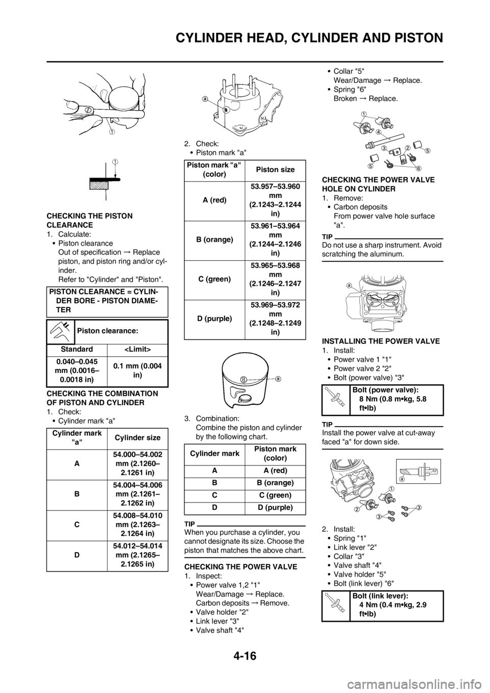
CHECKING THE POWER VALVE
1. Inspect:
• Power valve 1,2 "1"
Wear/Damage → Replace.
Carbon deposits → R e m o v e .
• Valve holder "2"
• Link lever "3"
• Valve shaft "4"•Collar "5"
Wear/Damage → Replace.
• Spring "6"
Broken → Replace.
CHECKING THE POWER VALVE
HOLE ON CYLINDER
1. Remove:
• Carbon deposits
From power valve hole surface
"a".
Do not use a sharp instrument. Avoid
scratching the aluminum.
INSTALLING THE POWER VALVE
1. Install:
• Power valve 1 "1"
• Power valve 2 "2"
• Bolt (power valve) "3"
Install the power valve at cut-away
faced "a" for down side.
2. Install:
• Spring "1"
• Link lever "2"
•Collar "3"
• Valve shaft "4"
• Valve holder "5"
• Bolt (link lever) "6" PISTON CLEARANCE = CYLIN-
DER BORE - PISTON DIAME-
TER
Piston clearance:
Standard
0.040–0.045
mm (0.0016–
0.0018 in)0.1 mm (0.004
in)
Cylinder mark
"a"Cylinder size
A54.000–54.002
mm (2.1260–
2.1261 in)
B54.004–54.006
mm (2.1261–
2.1262 in)
C54.008–54.010
mm (2.1263–
2.1264 in)
D54.012–54.014
mm (2.1265–
2.1265 in)
Piston mark "a"
(color)Piston size
A (red)53.957–53.960
mm
(2.1243–2.1244
in)
B (orange)53.961–53.964
mm
(2.1244–2.1246
in)
C (green)53.965–53.968
mm
(2.1246–2.1247
in)
D (purple)53.969–53.972
mm
(2.1248–2.1249
in)
Cylinder markPiston mark
(color)
AA (red)
BB (orange)
CC (green)
D D (purple)
Bolt (power valve):
8 Nm (0.8 m•kg, 5.8
ft•lb)
Bolt (link lever):
4 Nm (0.4 m•kg, 2.9
ft•lb)
Page 79 of 168
4-17
CYLINDER HEAD, CYLINDER AND PISTON
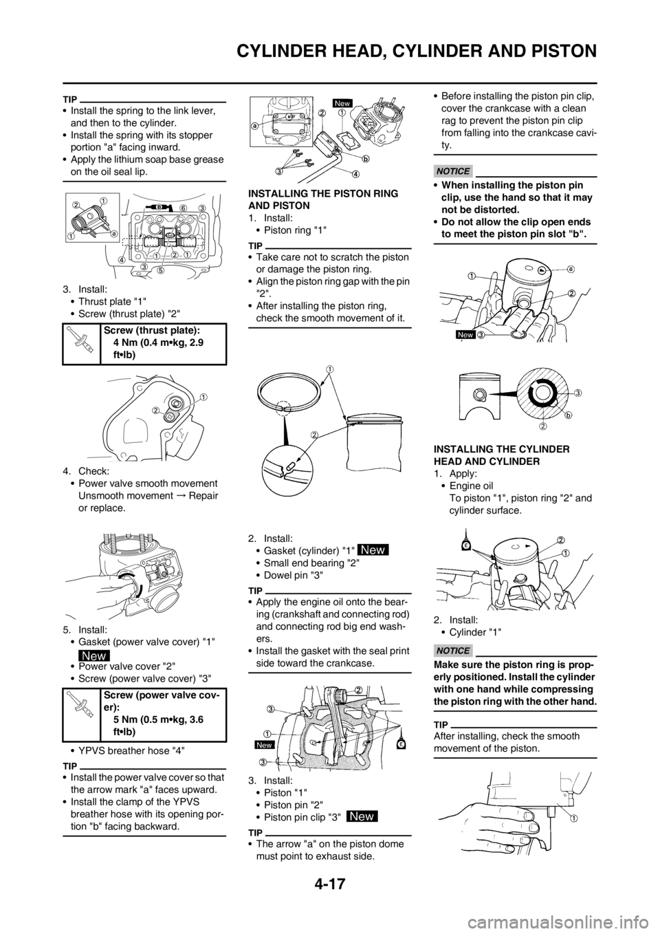
• Install the spring to the link lever,
and then to the cylinder.
• Install the spring with its stopper
portion "a" facing inward.
• Apply the lithium soap base grease
on the oil seal lip.
3. Install:
• Thrust plate "1"
• Screw (thrust plate) "2"
4. Check:
• Power valve smooth movement
Unsmooth movement → Repair
or replace.
5. Install:
• Gasket (power valve cover) "1"
• Power valve cover "2"
• Screw (power valve cover) "3"
• YPVS breather hose "4"
• Install the power valve cover so that
the arrow mark "a" faces upward.
• Install the clamp of the YPVS
breather hose with its opening por-
tion "b" facing backward.
INSTALLING THE PISTON RING
AND PISTON
1. Install:
• Piston ring "1"
• Take care not to scratch the piston
or damage the piston ring.
• Align the piston ring gap with the pin
"2".
• After installing the piston ring,
check the smooth movement of it.
2. Install:
• Gasket (cylinder) "1"
• Small end bearing "2"
• Dowel pin "3"
• Apply the engine oil onto the bear-
ing (crankshaft and connecting rod)
and connecting rod big end wash-
ers.
• Install the gasket with the seal print
side toward the crankcase.
3. Install:
•Piston "1"
• Piston pin "2"
• Piston pin clip "3"
• The arrow "a" on the piston dome
must point to exhaust side.• Before installing the piston pin clip,
cover the crankcase with a clean
rag to prevent the piston pin clip
from falling into the crankcase cavi-
ty.
• When installing the piston pin
clip, use the hand so that it may
not be distorted.
• Do not allow the clip open ends
to meet the piston pin slot "b".
INSTALLING THE CYLINDER
HEAD AND CYLINDER
1. Apply:
• Engine oil
To piston "1", piston ring "2" and
cylinder surface.
2. Install:
• Cylinder "1"
Make sure the piston ring is prop-
erly positioned. Install the cylinder
with one hand while compressing
the piston ring with the other hand.
After installing, check the smooth
movement of the piston.
Screw (thrust plate):
4 Nm (0.4 m•kg, 2.9
ft•lb)
Screw (power valve cov-
er):
5 Nm (0.5 m•kg, 3.6
ft•lb)
Page 80 of 168
4-18
CYLINDER HEAD, CYLINDER AND PISTON
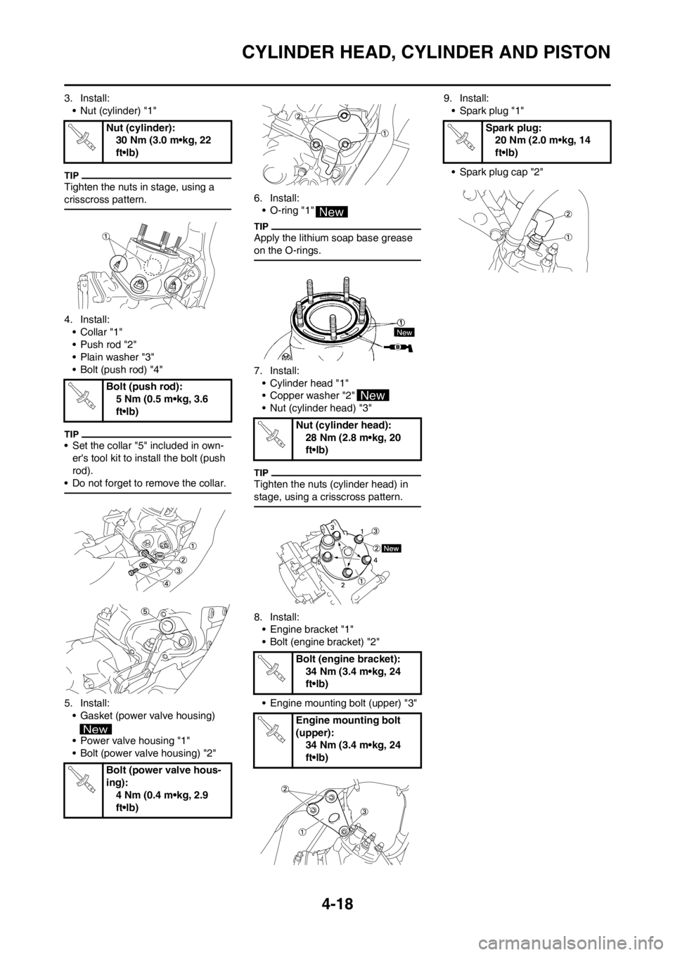
3. Install:
• Nut (cylinder) "1"
Tighten the nuts in stage, using a
crisscross pattern.
4. Install:
•Collar "1"
• Push rod "2"
• Plain washer "3"
• Bolt (push rod) "4"
• Set the collar "5" included in own-
er's tool kit to install the bolt (push
rod).
• Do not forget to remove the collar.
5. Install:
• Gasket (power valve housing)
• Power valve housing "1"
• Bolt (power valve housing) "2" 6. Install:
• O-ring "1"
Apply the lithium soap base grease
on the O-rings.
7. Install:
• Cylinder head "1"
• Copper washer "2"
• Nut (cylinder head) "3"
Tighten the nuts (cylinder head) in
stage, using a crisscross pattern.
8. Install:
• Engine bracket "1"
• Bolt (engine bracket) "2"
• Engine mounting bolt (upper) "3"9. Install:
• Spark plug "1"
• Spark plug cap "2" Nut (cylinder):
30 Nm (3.0 m•kg, 22
ft•lb)
Bolt (push rod):
5 Nm (0.5 m•kg, 3.6
ft•lb)
Bolt (power valve hous-
ing):
4 Nm (0.4 m•kg, 2.9
ft•lb)
Nut (cylinder head):
28 Nm (2.8 m•kg, 20
ft•lb)
Bolt (engine bracket):
34 Nm (3.4 m•kg, 24
ft•lb)
Engine mounting bolt
(upper):
34 Nm (3.4 m•kg, 24
ft•lb)
Spark plug:
20 Nm (2.0 m•kg, 14
ft•lb)