YAMAHA YZ85 2014 Owner's Guide
Manufacturer: YAMAHA, Model Year: 2014, Model line: YZ85, Model: YAMAHA YZ85 2014Pages: 88, PDF Size: 1.8 MB
Page 31 of 88
INSTRUMENT AND CONTROL FUNCTIONS
4-5
4
wash with soap an
d water. If gaso-
line spills on your clothin g, chan ge
your clothes.
EAU41362
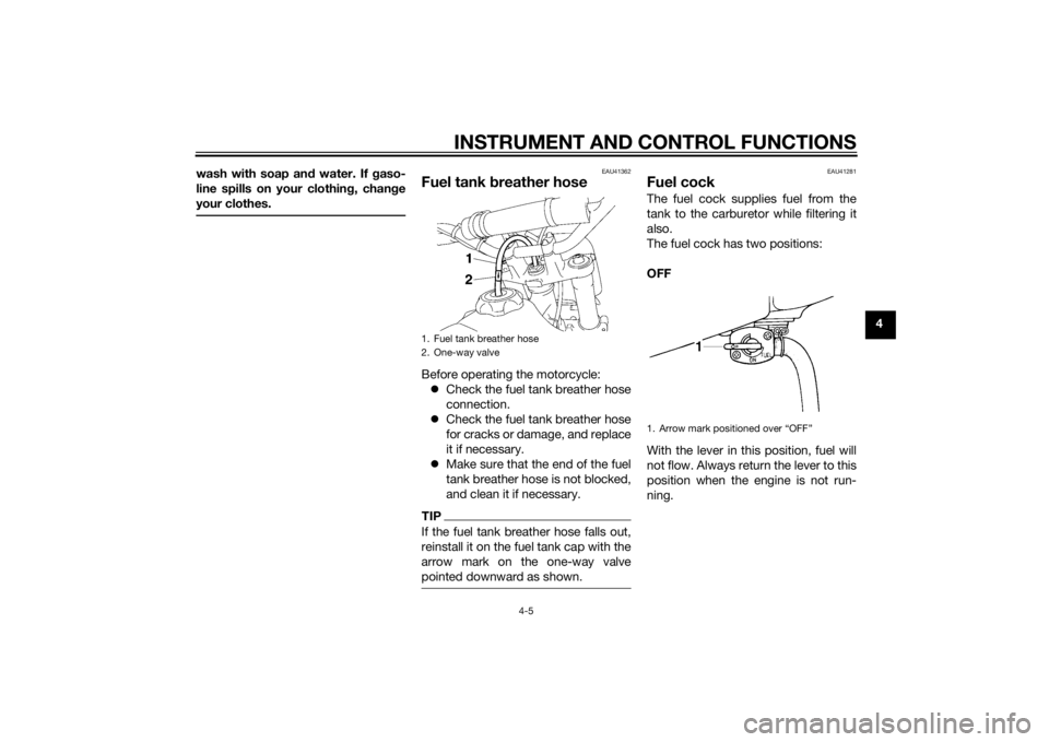
Fuel tank breather hoseBefore operating the motorcycle:
Check the fuel tank breather hose
connection.
Check the fuel tank breather hose
for cracks or damage, and replace
it if necessary.
Make sure that the end of the fuel
tank breather hose is not blocked,
and clean it if necessary.TIPIf the fuel tank breather hose falls out,
reinstall it on the fuel tank cap with the
arrow mark on the one-way valve
pointed downward as shown.
EAU41281
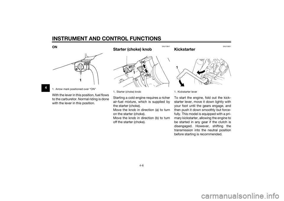
Fuel cockThe fuel cock supplies fuel from the
tank to the carburetor while filtering it
also.
The fuel cock has two positions:
OFF
With the lever in this position, fuel will
not flow. Always return the lever to this
position when the engine is not run-
ning.
1. Fuel tank breather hose
2. One-way valve
1. Arrow mark positioned over “OFF”
U1SN82E0.book Page 5 Friday, June 7, 2013 3:51 PM
Page 32 of 88
INSTRUMENT AND CONTROL FUNCTIONS
4-6
4ON
With the lever in this position, fuel flows
to the carburetor. Normal riding is done
with the lever in this position.
EAU13641
Starter (choke) kno
bStarting a cold engine requires a richer
air-fuel mixture, which is supplied by
the starter (choke).
Move the knob in direction (a) to turn
on the starter (choke).
Move the knob in direction (b) to turn
off the starter (choke).
EAU13651
KickstarterTo start the engine, fold out the kick-
starter lever, move it down lightly with
your foot until the gears engage, and
then push it down smoothly but force-
fully. This model is equipped with a pri-
mary kickstarter, allowing the engine to
be started in any gear if the clutch is
disengaged. However, shifting the
transmission into the neutral position
before starting is recommended.
1. Arrow mark positioned over “ON”
1. Starter (choke) knob
1. Kickstarter lever
U1SN82E0.book Page 6 Friday, June 7, 2013 3:51 PM
Page 33 of 88
INSTRUMENT AND CONTROL FUNCTIONS
4-7
4
EAU46283
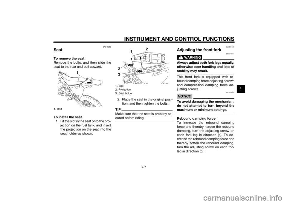
SeatTo remove the seat
Remove the bolts, and then slide the
seat to the rear and pull upward.
To install the seat1. Fit the slot in the seat onto the pro- jection on the fuel tank, and insert
the projection on the seat into the
seat holder as shown. 2. Place the seat in the original posi-
tion, and then tighten the bolts.
TIPMake sure that the seat is properly se-
cured before riding.
EAU41473
Adjustin g the front fork
WARNING
EWA10181
Always a djust both fork le gs equally,
otherwise poor han dlin g an d loss of
sta bility may result.This front fork is equipped with re-
bound damping force adjusting screws
and compression damping force ad-
justing screws.NOTICE
ECA10102
To avoi d d amag ing the mechanism,
d o not attempt to turn beyon d the
maximum or minimum settin gs.Re boun d d ampin g force
To increase the rebound damping
force and thereby harden the rebound
damping, turn the adjusting screw on
each fork leg in direction (a). To de-
crease the rebound damping force and
thereby soften the rebound damping,
turn the adjusting screw on each fork
leg in direction (b).
1. Bolt
1. Slot
2. Projection
3. Seat holder
1 2
2
3
U1SN82E0.book Page 7 Friday, June 7, 2013 3:51 PM
Page 34 of 88
INSTRUMENT AND CONTROL FUNCTIONS
4-8
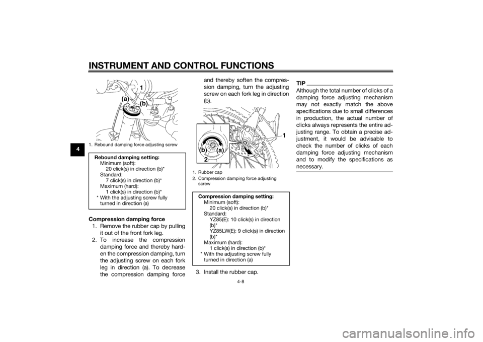
4Compression dampin g force
1. Remove the rubber cap by pulling it out of the front fork leg.
2. To increase the compression damping force and thereby hard-
en the compression damping, turn
the adjusting screw on each fork
leg in direction (a). To decrease
the compression damping force and thereby soften the compres-
sion damping, turn the adjusting
screw on each fork leg in direction
(b).
3. Install the rubber cap.
TIPAlthough the total number of clicks of a
damping force adjusting mechanism
may not exactly match the above
specifications due to small differences
in production, the actual number of
clicks always represents the entire ad-
justing range. To obtain a precise ad-
justment, it would be advisable to
check the number of clicks of each
damping force adjusting mechanism
and to modify the specifications as
necessary.
1. Rebound damping force adjusting screwRe boun d d ampin g setting :
Minimum (soft): 20 click(s) in direction (b)*
Standard: 7 click(s) in direction (b)*
Maximum (hard):
1 click(s) in direction (b)*
* With the adjusting screw fully turned in direction (a)
1. Rubber cap
2. Compression damping force adjusting
screwCompression dampin g settin g:
Minimum (soft): 20 click(s) in direction (b)*
Standard:
YZ85(E): 10 click(s) in direction
(b)*
YZ85LW(E): 9 click(s) in direction
(b)*
Maximum (hard): 1 click(s) in direction (b)*
* With the adjusting screw fully turned in direction (a)
U1SN82E0.book Page 8 Friday, June 7, 2013 3:51 PM
Page 35 of 88
INSTRUMENT AND CONTROL FUNCTIONS
4-9
4
EAU51651
Front fork bleedin g
WARNING
EWA10201
Always blee d b oth fork le gs, other-
wise poor han dlin g an d loss of sta-
b ility may result.When riding in extremely rough condi-
tions, the air temperature and pressure
in the front fork will rise. This will in-
crease the spring preload and harden
the front suspension. If this occurs,
bleed the front fork as follows.
1. Lift the front wheel off the ground according to the procedure on
page 7-28.TIPWhen bleeding the front fork, there
should be no weight on the front end of
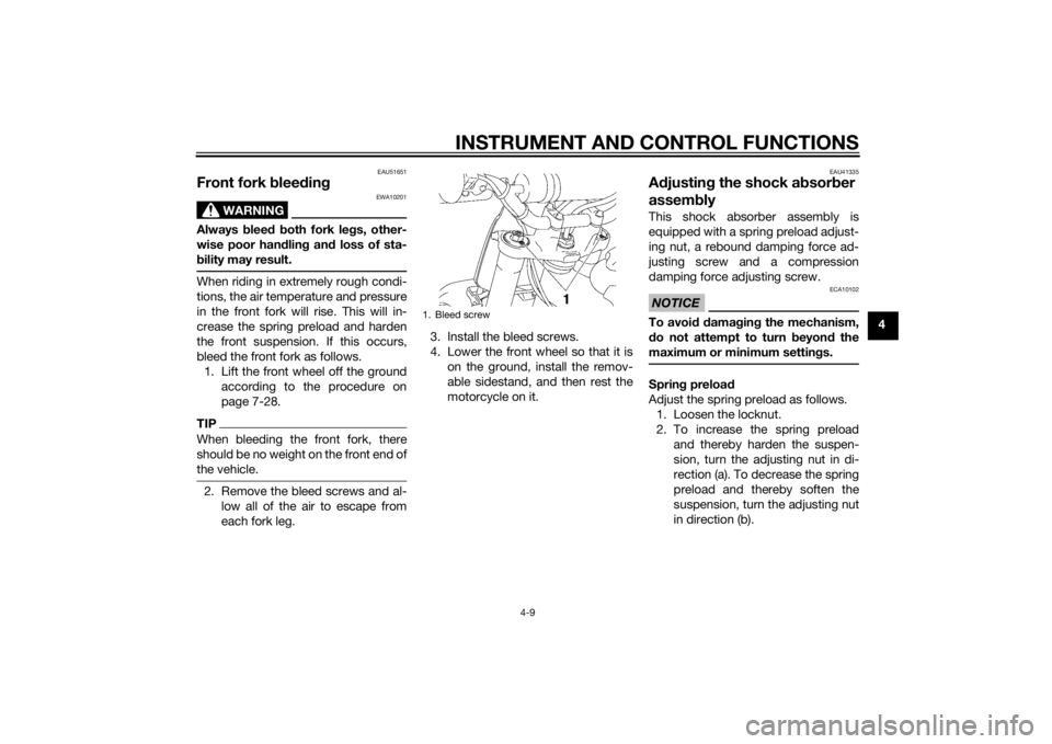
the vehicle.2. Remove the bleed screws and al-low all of the air to escape from
each fork leg. 3. Install the bleed screws.
4. Lower the front wheel so that it is
on the ground, install the remov-
able sidestand, and then rest the
motorcycle on it.
EAU41335
Adjustin g the shock a bsor ber
assem blyThis shock absorber assembly is
equipped with a spring preload adjust-
ing nut, a rebound damping force ad-
justing screw and a compression
damping force adjusting screw.NOTICE
ECA10102
To avoi d d amag ing the mechanism,
d o not attempt to turn beyon d the
maximum or minimum settin gs.Sprin g preloa d
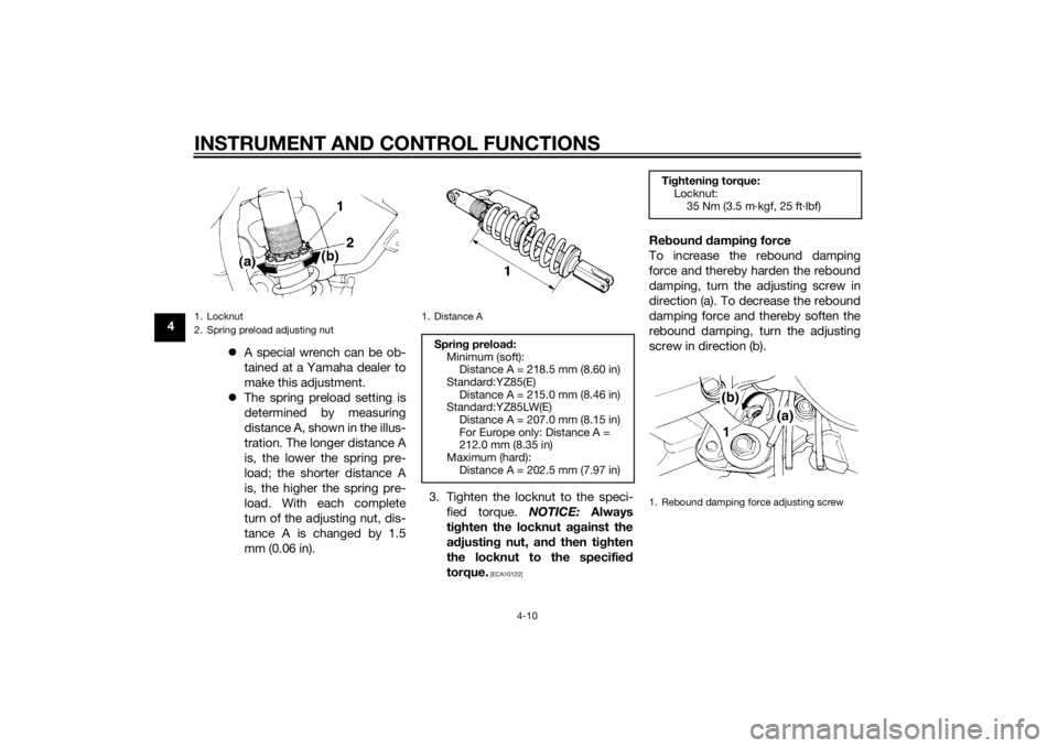
Adjust the spring preload as follows. 1. Loosen the locknut.
2. To increase the spring preload and thereby harden the suspen-
sion, turn the adjusting nut in di-
rection (a). To decrease the spring
preload and thereby soften the
suspension, turn the adjusting nut
in direction (b).
1. Bleed screw
U1SN82E0.book Page 9 Friday, June 7, 2013 3:51 PM
Page 36 of 88
INSTRUMENT AND CONTROL FUNCTIONS
4-10
4A special wrench can be ob-
tained at a Yamaha dealer to
make this adjustment.
The spring preload setting is
determined by measuring
distance A, shown in the illus-
tration. The longer distance A
is, the lower the spring pre-
load; the shorter distance A
is, the higher the spring pre-
load. With each complete
turn of the adjusting nut, dis-
tance A is changed by 1.5
mm (0.06 in). 3. Tighten the locknut to the speci-
fied torque. NOTICE: Always
ti g hten the locknut ag ainst the
a d justin g nut, and then tighten
the locknut to the specified
torque.
[ECA10122]
Re boun d d ampin g force
To increase the rebound damping
force and thereby harden the rebound
damping, turn the adjusting screw in
direction (a). To decrease the rebound
damping force and thereby soften the
rebound damping, turn the adjusting
screw in direction (b).
1. Locknut
2. Spring preload adjusting nut
1. Distance ASprin g preloa d:
Minimum (soft): Distance A = 218.5 mm (8.60 in)
Standard:YZ85(E) Distance A = 215.0 mm (8.46 in)
Standard:YZ85LW(E)
Distance A = 207.0 mm (8.15 in)
For Europe only: Distance A =
212.0 mm (8.35 in)
Maximum (hard): Distance A = 202.5 mm (7.97 in)
Tightenin g torque:
Locknut:
35 Nm (3.5 m·kgf, 25 ft·lbf)1. Rebound damping force adjusting screw
U1SN82E0.book Page 10 Friday, June 7, 2013 3:51 PM
Page 37 of 88
INSTRUMENT AND CONTROL FUNCTIONS
4-11
4
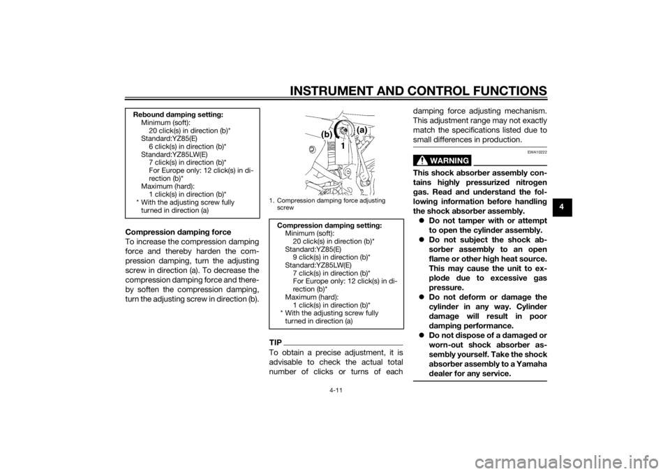
Compression dampin g force
To increase the compression damping
force and thereby harden the com-
pression damping, turn the adjusting
screw in direction (a). To decrease the
compression damping force and there-
by soften the compression damping,
turn the adjusting screw in direction (b).
TIPTo obtain a precise adjustment, it is
advisable to check the actual total
number of clicks or turns of each damping force adjusting mechanism.
This adjustment range may not exactly
match the specifications listed due to
small differences in production.
WARNING
EWA10222
This shock a
bsor ber assem bly con-
tains hig hly pressurize d nitro gen
g as. Rea d an d un derstan d the fol-
lowin g information before han dlin g
the shock a bsor ber assem bly.
Do not tamper with or attempt
to open the cylind er assembly.
Do not su bject the shock a b-
sor ber assem bly to an open
flame or other hi gh heat source.
This may cause the unit to ex-
plo de due to excessive gas
pressure.
Do not deform or damag e the
cylin der in any way. Cylin der
d ama ge will result in poor
d ampin g performance.
Do not dispose of a damag ed or
worn-out shock a bsor ber as-
sem bly
yourself. Take the shock
a b sor ber assem bly to a Yamaha
d ealer for any service.
Re boun d d ampin g settin g:
Minimum (soft):
20 click(s) in direction (b)*
Standard:YZ85(E)
6 click(s) in direction (b)*
Standard:YZ85LW(E) 7 click(s) in direction (b)*
For Europe only: 12 click(s) in di-
rection (b)*
Maximum (hard):
1 click(s) in direction (b)*
* With the adjusting screw fully turned in direction (a)
1. Compression damping force adjusting
screw
Compression dampin g setting :
Minimum (soft): 20 click(s) in direction (b)*
Standard:YZ85(E) 9 click(s) in direction (b)*
Standard:YZ85LW(E)
7 click(s) in direction (b)*
For Europe only: 12 click(s) in di-
rection (b)*
Maximum (hard): 1 click(s) in direction (b)*
* With the adjusting screw fully
turned in direction (a)
U1SN82E0.book Page 11 Friday, June 7, 2013 3:51 PM
Page 38 of 88
INSTRUMENT AND CONTROL FUNCTIONS
4-12
4
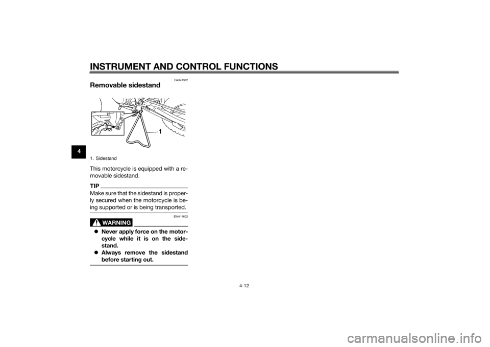
EAU41382
Removable si destan dThis motorcycle is equipped with a re-
movable sidestand.TIPMake sure that the sidestand is proper-
ly secured when the motorcycle is be-
ing supported or is being transported.
WARNING
EWA14602
Never apply force on the motor-
cycle while it is on the si de-
stan d.
Always remove the si destan d
b efore startin g out.1. SidestandU1SN82E0.book Page 12 Friday, June 7, 2013 3:51 PM
Page 39 of 88
FOR YOUR SAFETY – PRE-OPERATION CHECKS
5-1
5
EAU15598
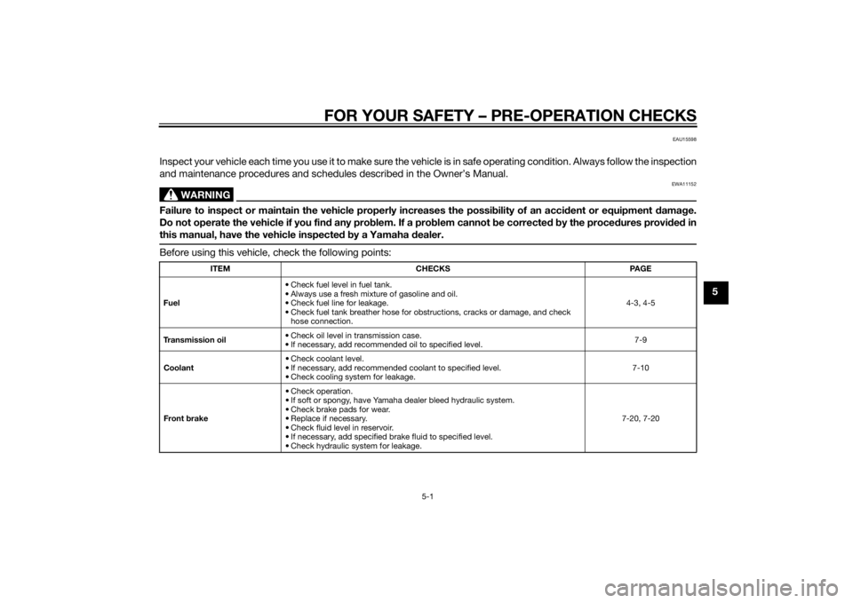
Inspect your vehicle each time you use it to make sure the vehicle is in safe operating condition. Always follow the inspection
and maintenance procedures and schedules described in the Owner’s Manual.
WARNING
EWA11152
Failure to inspect or maintain the vehicle properly increases the possibility of an acci dent or equipment damag e.
Do not operate the vehicle if you fin d any pro blem. If a pro blem cannot be corrected b y the proce dures provi ded in
this manual, have the vehicle inspecte d b y a Yamaha dealer.Before using this vehicle, check the following points:
ITEM CHECKS PAGE
Fuel • Check fuel level in fuel tank.
• Always use a fresh mixture of gasoline and oil.
• Check fuel line for leakage.
• Check fuel tank breather hose for obstructions, cracks or damage, and check
hose connection. 4-3, 4-5
Transmission oil • Check oil level in transmission case.
• If necessary, add recommended oil to specified level. 7-9
Coolant • Check coolant level.
• If necessary, add recommended coolant to specified level.
• Check cooling system for leakage. 7-10
Front brake • Check operation.
• If soft or spongy, have Yamaha dealer bleed hydraulic system.
• Check brake pads for wear.
• Replace if necessary.
• Check fluid level in reservoir.
• If necessary, add specified brake fluid to specified level.
• Check hydraulic system for leakage. 7-20, 7-20
U1SN82E0.book Page 1 Friday, June 7, 2013 3:51 PM
Page 40 of 88

FOR YOUR SAFETY – PRE-OPERATION CHECKS
5-2
5
Rear brake • Check operation.
• If soft or spongy, have Yamaha dealer bleed hydraulic system.
• Check brake pads for wear.
• Replace if necessary.
• Check fluid level in reservoir.
• If necessary, add specified brake fluid to specified level.
• Check hydraulic system for leakage. 7-20, 7-20
Clutch • Check operation.
• Lubricate cable if necessary.
• Check lever free play.
• Adjust if necessary.
7-18
Throttle g rip • Make sure that operation is smooth.
• Check throttle grip free play.
• If necessary, have Yamaha dealer adjust throttle grip free play and lubricate ca-
ble and grip housing. 7-15, 7-24
Drive chain • Check chain slack.
• Adjust if necessary.
• Check chain condition.
• Lubricate if necessary. 7-22, 7-23
Wheels an d tires •Check for damage.
• Check tire condition and tread depth.
• Check air pressure.
• Correct if necessary.
• Check for loose spokes and tighten if necessary. 7-15, 7-17
Shift pe dal • Make sure that operation is smooth.
• Correct if necessary.
7-19
Brake ped al • Make sure that operation is smooth.
• Lubricate pedal pivoting point if necessary. 7-25
Brake an d clutch levers • Make sure that operation is smooth.
• Lubricate lever pivoting points if necessary.
7-24
Steerin g • Check that the handlebar can be turned smoothly and has no excessive play. 7-27
ITEM
CHECKS PAGE
U1SN82E0.book Page 2 Friday, June 7, 2013 3:51 PM