ACURA NSX 1991 Service Repair Manual
Manufacturer: ACURA, Model Year: 1991, Model line: NSX, Model: ACURA NSX 1991Pages: 1640, PDF Size: 60.48 MB
Page 271 of 1640
Throttle Bod y
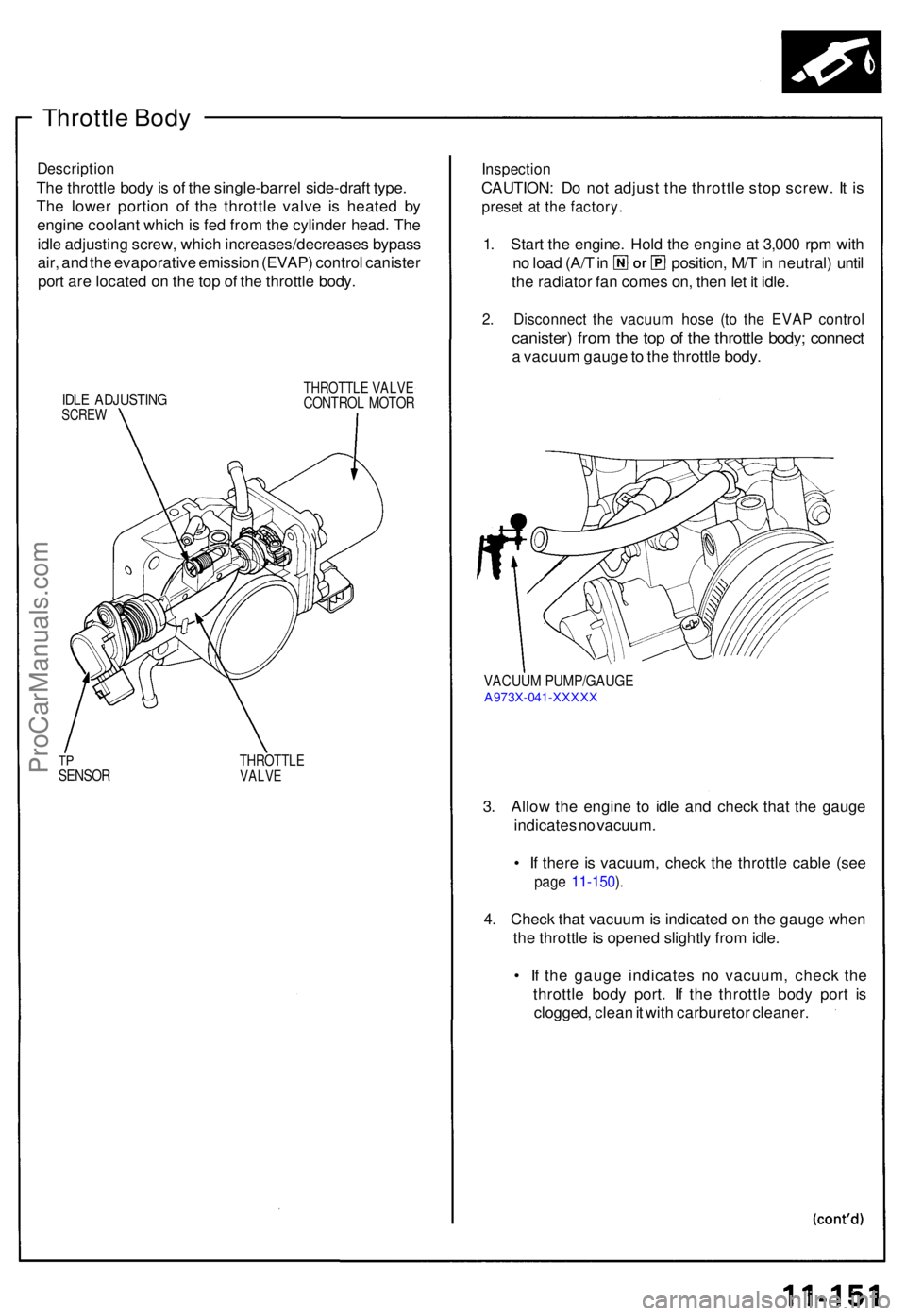
Descriptio n
The throttl e bod y is o f th e single-barre l side-draf t type .
Th e lowe r portio n o f th e throttl e valv e i s heate d b y
engin e coolan t whic h is fe d fro m th e cylinde r head . Th e
idl e adjustin g screw , whic h increases/decrease s bypas s
air , an d th e evaporativ e emissio n (EVAP ) contro l caniste r
por t ar e locate d o n th e to p o f th e throttl e body .
IDLE ADJUSTIN GSCREW
THROTTL E VALV ECONTRO L MOTO R
TPSENSO RTHROTTL EVALVE
Inspectio n
CAUTION : D o no t adjus t th e throttl e sto p screw . I t i s
prese t a t th e factory .
1. Star t th e engine . Hol d th e engin e a t 3,00 0 rp m wit h
no loa d (A/ T in position , M/ T in neutral ) unti l
th e radiato r fa n come s on , the n le t i t idle .
2. Disconnec t th e vacuu m hos e (t o th e EVA P contro l
canister ) fro m th e to p o f th e throttl e body ; connec t
a vacuu m gaug e to th e throttl e body .
VACUU M PUMP/GAUG EA973X-04 1-XXXX X
3. Allo w th e engin e t o idl e an d chec k tha t th e gaug e
indicate s n o vacuum .
• I f ther e i s vacuum , chec k th e throttl e cabl e (se e
page 11-150 ).
4 . Chec k tha t vacuu m is indicate d o n th e gaug e whe n
th e throttl e is opene d slightl y fro m idle .
• I f th e gaug e indicate s n o vacuum , chec k th e
throttl e bod y port . I f th e throttl e bod y por t i s
clogged , clea n it wit h carbureto r cleaner .
ProCarManuals.com
Page 272 of 1640
Intake Air System
Throttle Body
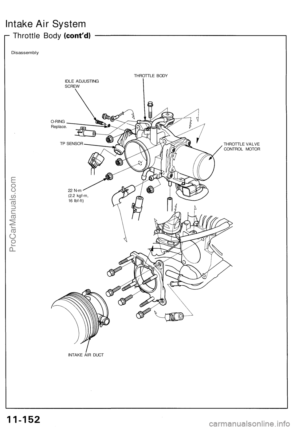
Disassembly
THROTTLE BODY
IDLE ADJUSTING
SCREW
O-RING
Replace.
THROTTLE VALVE
CONTROL MOTOR
INTAKE AIR DUCT
TP SENSOR
22 N-m
(2.2 kgf-m,
16 Ibf-ft)ProCarManuals.com
Page 273 of 1640
Fuel Injection Air (FIA) Control System
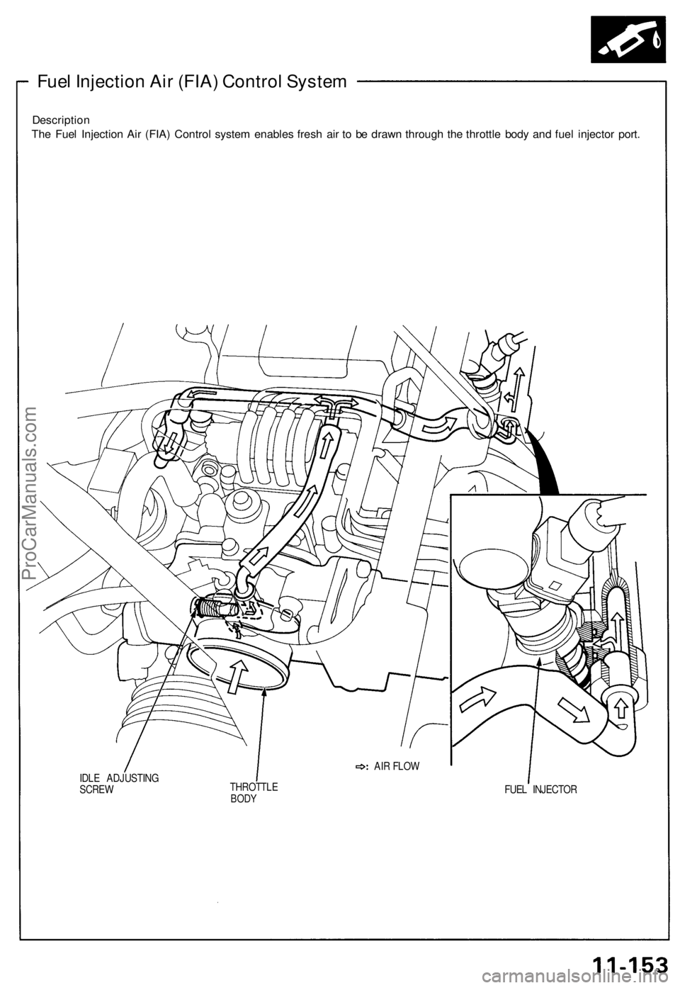
Description
The Fuel Injection Air (FIA) Control system enables fresh air to be drawn through the throttle body and fuel injector port.
IDLE ADJUSTING
SCREW
THROTTLE
BODY
FUEL INJECTOR
AIR FLOWProCarManuals.com
Page 274 of 1640
Intake Air System
Intake Air Bypass (IAB) Control System
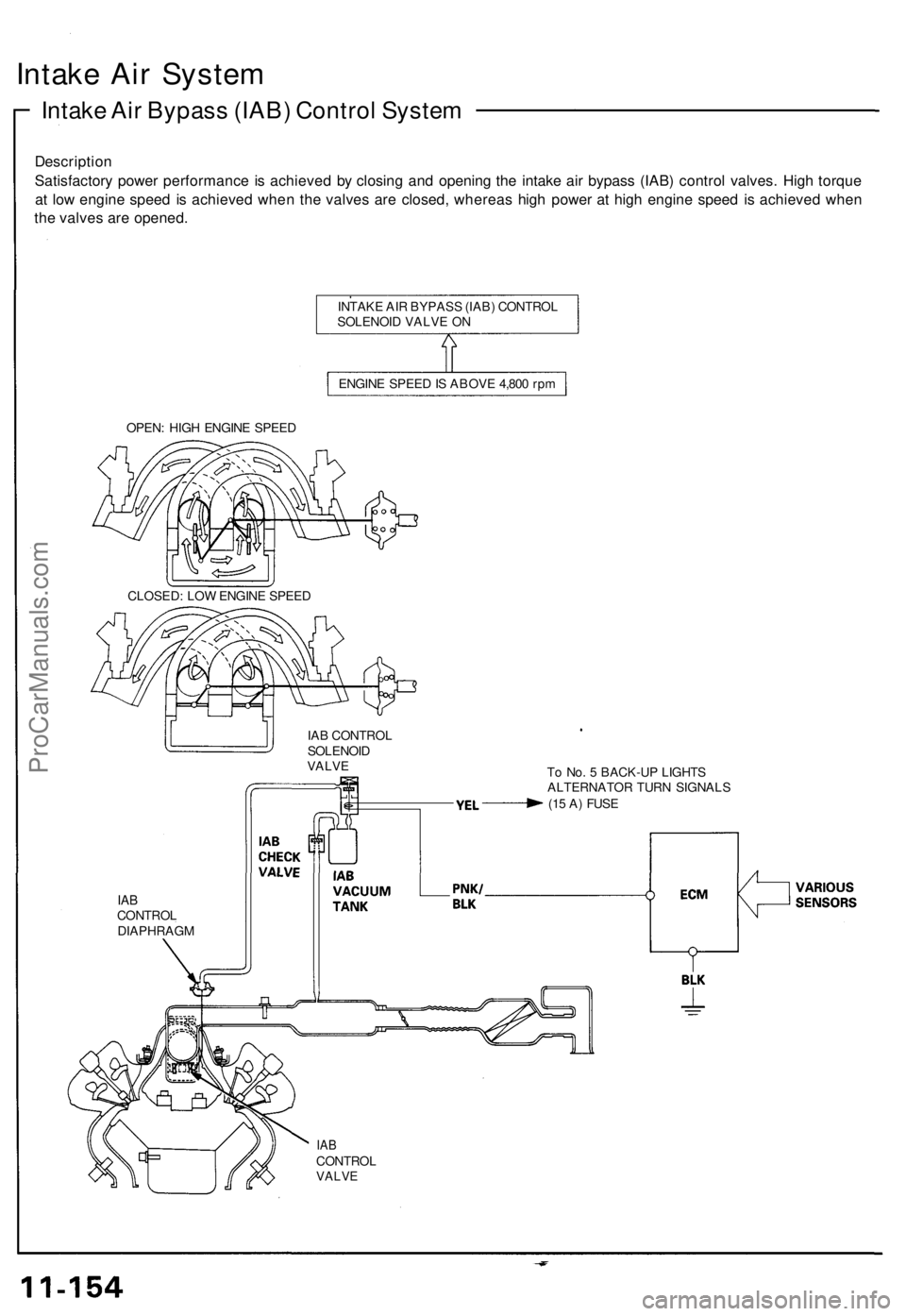
Description
Satisfactory power performance is achieved by closing and opening the intake air bypass (IAB) control valves. High torque
at low engine speed is achieved when the valves are closed, whereas high power at high engine speed is achieved when
the valves are opened.
INTAKE AIR BYPASS (IAB) CONTROL
SOLENOID VALVE ON
ENGINE SPEED IS ABOVE 4,800 rpm
OPEN: HIGH ENGINE SPEED
IAB CONTROL
SOLENOID
VALVE
To No. 5 BACK-UP LIGHTS
ALTERNATOR TURN SIGNALS
(15 A) FUSE
IAB
CONTROL
DIAPHRAGM
IAB
CONTROL
VALVE
CLOSED: LOW ENGINE SPEEDProCarManuals.com
Page 275 of 1640
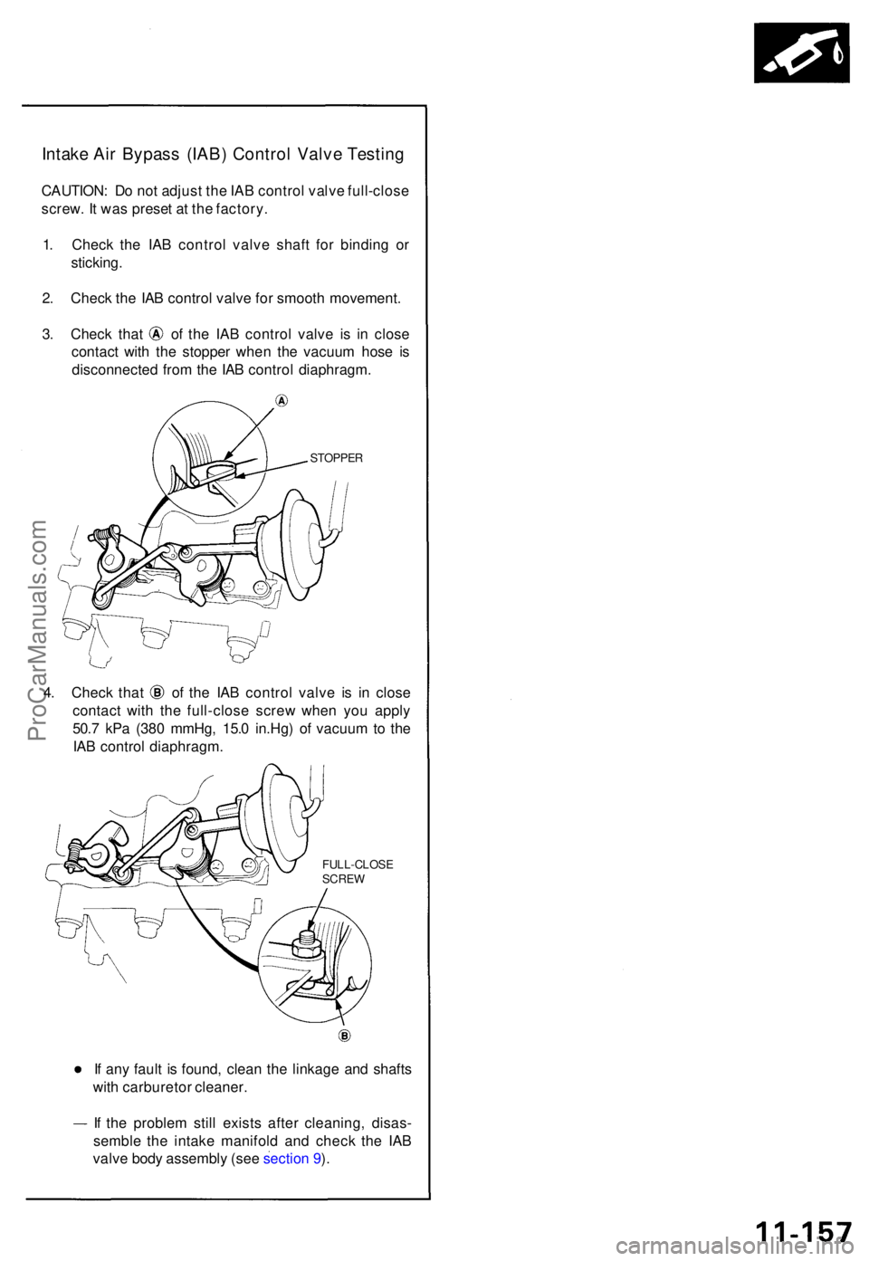
Intake Ai r Bypas s (IAB ) Contro l Valv e Testin g
CAUTION : D o no t adjus t th e IA B contro l valv e full-clos e
screw . I t wa s prese t a t th e factory .
1 . Chec k th e IA B contro l valv e shaf t fo r bindin g o r
sticking .
2 . Chec k th e IA B contro l valv e fo r smoot h movement .
3. Chec k tha t o f th e IA B contro l valv e i s i n clos e
contac t wit h th e stoppe r whe n th e vacuu m hos e i s
disconnecte d fro m th e IA B contro l diaphragm .
STOPPER
4. Chec k tha t of the IA B contro l valv e i s i n clos e
contac t wit h th e full-clos e scre w whe n yo u appl y
50. 7 kP a (38 0 mmHg , 15. 0 in.Hg ) o f vacuu m to th e
IA B contro l diaphragm .
FULL-CLOS E
SCRE W
If an y faul t i s found , clea n th e linkag e an d shaft s
wit h carbureto r cleaner .
I f th e proble m stil l exist s afte r cleaning , disas -
sembl e th e intak e manifol d an d chec k th e IA B
valv e bod y assembl y (se e sectio n 9 ).
ProCarManuals.com
Page 276 of 1640
Emission Contro l Syste m
System Descriptio n
The emissio n contro l syste m include s tw o Thre e Wa y
Catalyti c Converter s (TWCs) , Exhaus t Ga s Recirculatio n
(EGR ) system , Positiv e Crankcas e Ventilatio n (PCV ) sys -
te m an d Evaporativ e Emissio n (EVAP ) Contro l system .
Th e emissio n contro l syste m is designe d t o mee t federa l
an d stat e emissio n standards .
Tailpipe Emissio n
Inspectio n
Do no t smok e durin g thi s procedure . Kee p
an y ope n flam e awa y fro m you r wor k area .
1 . Star t th e engine . Hol d th e engin e a t 3,00 0 rp m wit h
no loa d (A/ T in position , M/ T in neutral ) unti l
the radiato r fa n come s on , the n le t i t idle .
2 . Connec t a tachometer .
3 . Chec k an d adjus t th e idl e speed , i f necessar y (se e
pag e 11-128 ).
4 . War m u p an d calibrat e th e C O mete r accordin g t o
th e mete r manufacturer' s instructions .
5 . Chec k idl e C O wit h th e headlights , heate r blower ,
rea r windo w defogger , coolin g fan , an d ai r condi -
tione r off .
NOTE : (Canada ) Pul l th e parkin g brak e leve r up .
Star t th e engine , the n chec k tha t th e headlight s ar e
off.
CO mete r shoul d indicat e 0.1 % maximum .
ProCarManuals.com
Page 277 of 1640
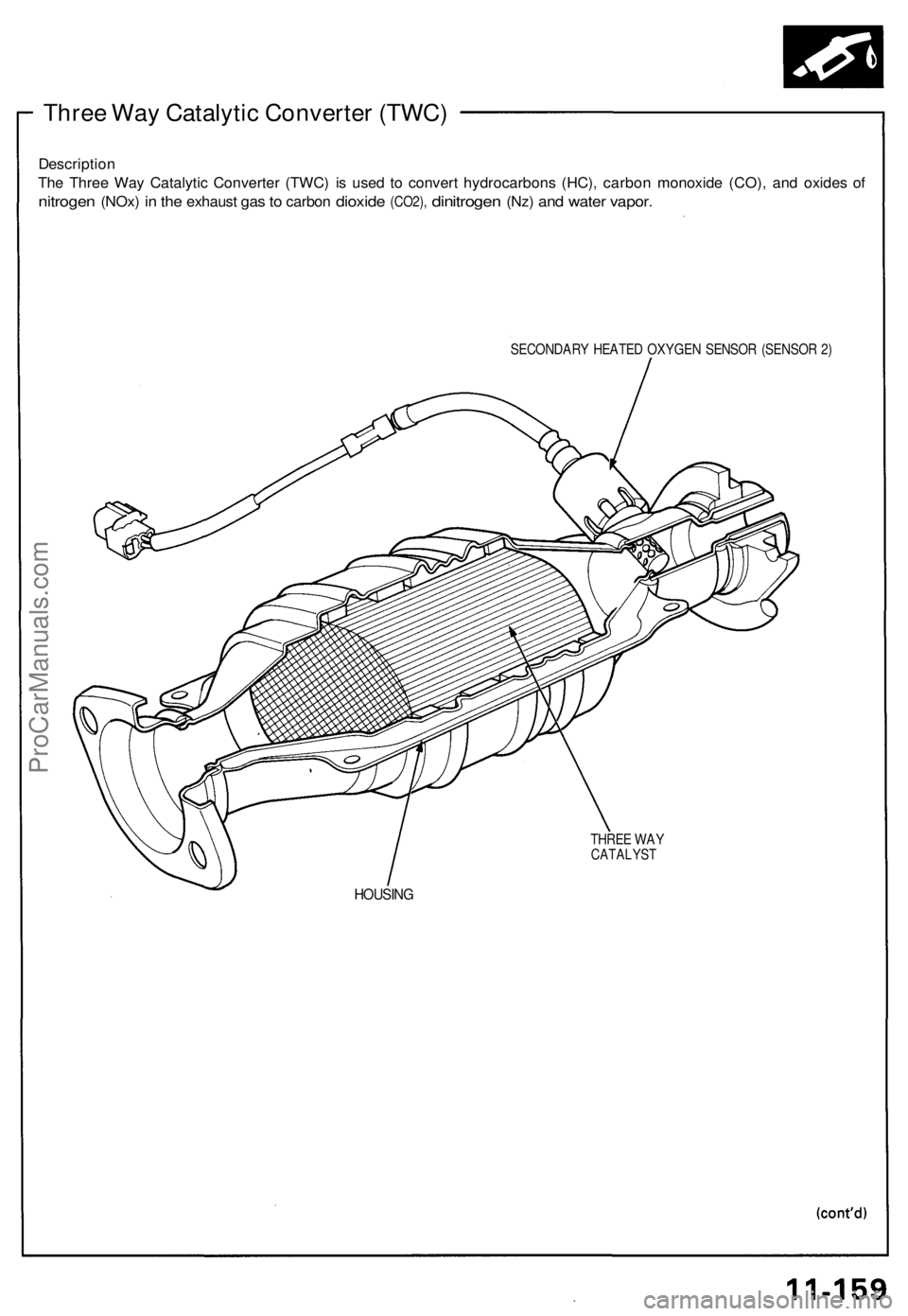
Three Way Catalytic Converter (TWC)
Description
The Three Way Catalytic Converter (TWC) is used to convert hydrocarbons (HC), carbon monoxide (CO), and oxides of
nitrogen
(NOx)
in the
exhaust
gas to
carbon
dioxide
(CO2),
dinitrogen
(Nz)
and
water
vapor.
SECONDARY HEATED OXYGEN SENSOR (SENSOR 2)
THREE WAY
CATALYST
HOUSINGProCarManuals.com
Page 278 of 1640
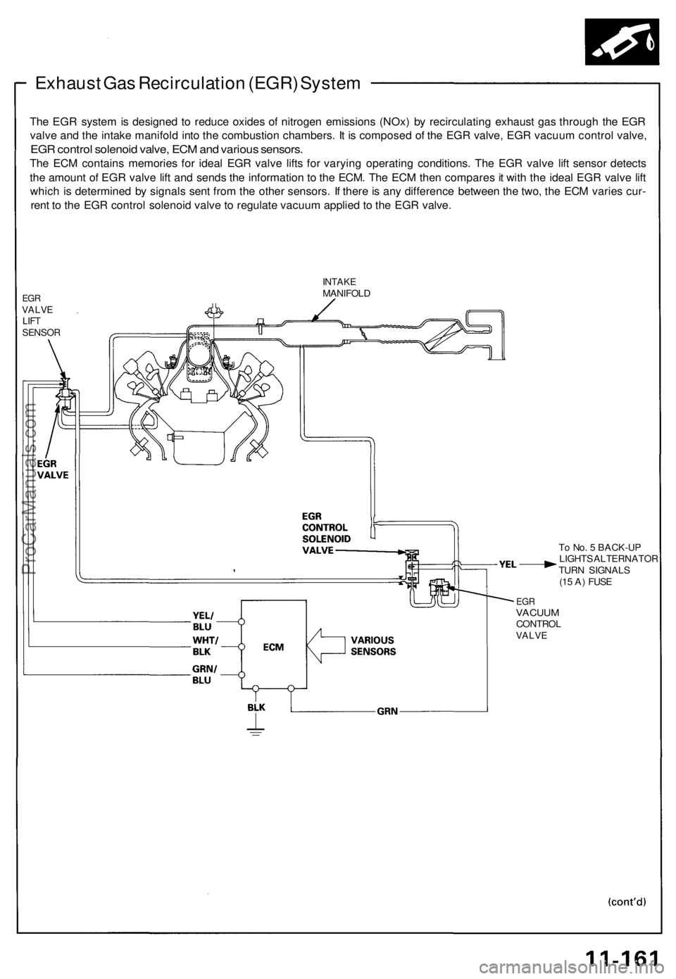
Exhaust Ga s Recirculatio n (EGR ) Syste m
The EG R syste m is designe d t o reduc e oxide s o f nitroge n emission s (NOx ) b y recirculatin g exhaus t ga s throug h th e EG R
valv e an d th e intak e manifol d int o th e combustio n chambers . I t i s compose d o f th e EG R valve , EG R vacuu m contro l valve ,
EGR contro l solenoi d valve , EC M an d variou s sensors .
The EC M contain s memorie s fo r idea l EG R valv e lift s fo r varyin g operatin g conditions . Th e EG R valv e lif t senso r detect s
th e amoun t o f EG R valv e lif t an d send s th e informatio n t o th e ECM . Th e EC M the n compare s it wit h th e idea l EG R valv e lif t
whic h i s determine d b y signal s sen t fro m th e othe r sensors . I f ther e is an y differenc e betwee n th e two , th e EC M varie s cur -
ren t t o th e EG R contro l solenoi d valv e to regulat e vacuu m applie d t o th e EG R valve .
EGRVALV ELIFTSENSO R
INTAKEMANIFOL D
To No . 5 BACK-U P
LIGHT S ALTERNATO R
TUR N SIGNAL S
(1 5 A ) FUS E
EGRVACUU MCONTRO LVALVE
ProCarManuals.com
Page 279 of 1640
Emission Control System
Positive Crankcas e Ventilatio n (PCV ) Syste m
Descriptio n
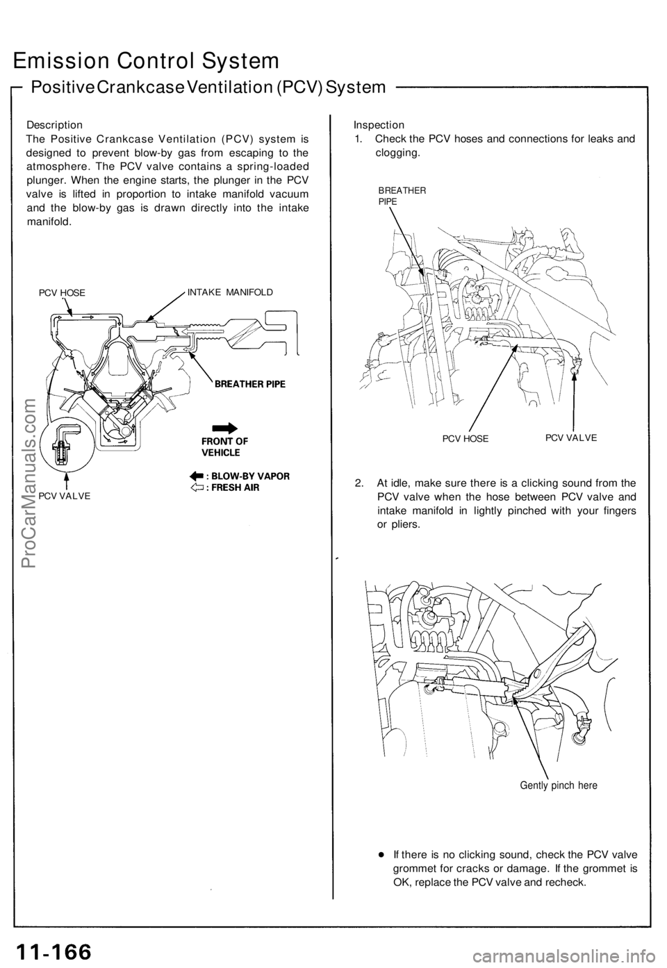
Th e Positiv e Crankcas e Ventilatio n (PCV ) syste m is
designe d t o preven t blow-b y ga s fro m escapin g t o th e
atmosphere . Th e PCV valve contain s a spring-loade d
plunger . Whe n th e engin e starts , th e plunge r i n th e PC V
valv e i s lifte d i n proportio n t o intak e manifol d vacuu m
an d th e blow-b y ga s i s draw n directl y int o th e intak e
manifold .
PCV HOS EINTAK E MANIFOL D
PCV VALV E
Inspectio n
1. Chec k th e PC V hose s an d connection s fo r leak s an d
clogging .
BREATHE RPIPE
PCV HOS E PC
V VALV E
2. A t idle , mak e sur e ther e i s a clickin g soun d fro m th e
PC V valv e whe n th e hos e betwee n PC V valv e an d
intak e manifol d i n lightl y pinche d wit h you r finger s
o r pliers .
Gently pinc h her e
If ther e i s n o clickin g sound , chec k th e PC V valv e
gromme t fo r crack s o r damage . I f th e gromme t i s
OK , replac e th e PC V valv e an d recheck .
ProCarManuals.com
Page 280 of 1640
Evaporative Emission (EVAP) Controls
Description
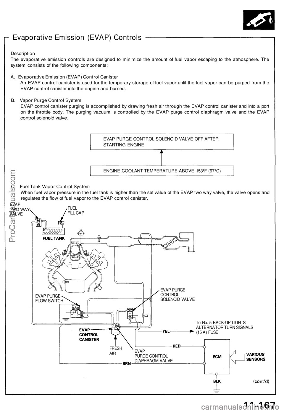
The evaporative emission controls are designed to minimize the amount of fuel vapor escaping to the atmosphere. The
system consists of the following components:
A. Evaporative Emission (EVAP) Control Canister
An EVAP control canister is used for the temporary storage of fuel vapor until the fuel vapor can be purged from the
EVAP control canister into the engine and burned.
B. Vapor Purge Control System
EVAP control canister purging is accomplished by drawing fresh air through the EVAP control canister and into a port
on the throttle body. The purging vacuum is controlled by the EVAP purge control diaphragm valve and the EVAP
control solenoid valve.
EVAP PURGE CONTROL SOLENOID VALVE OFF AFTER
STARTING ENGINE
ENGINE COOLANT TEMPERATURE ABOVE 153°F (67°C)
To No. 5 BACK-UP LIGHTS
ALTERNATOR TURN SIGNALS
(15 A) FUSE
FRESH
AIR
EVAP
PURGE CONTROL
DIAPHRAGM VALVE
EVAP PURGE
CONTROL
SOLENOID VALVE
EVAP PURGE
FLOW SWITCH
C. Fuel Tank Vapor Control System
When fuel vapor pressure in the fuel tank is higher than the set value of the EVAP two way valve, the valve opens and
regulates the flow of fuel vapor to the EVAP control canister.
EVAP
TWO WAY
VALVE
FUEL
FILL CAPProCarManuals.com