ACURA NSX 1991 Service Repair Manual
Manufacturer: ACURA, Model Year: 1991, Model line: NSX, Model: ACURA NSX 1991Pages: 1640, PDF Size: 60.48 MB
Page 231 of 1640
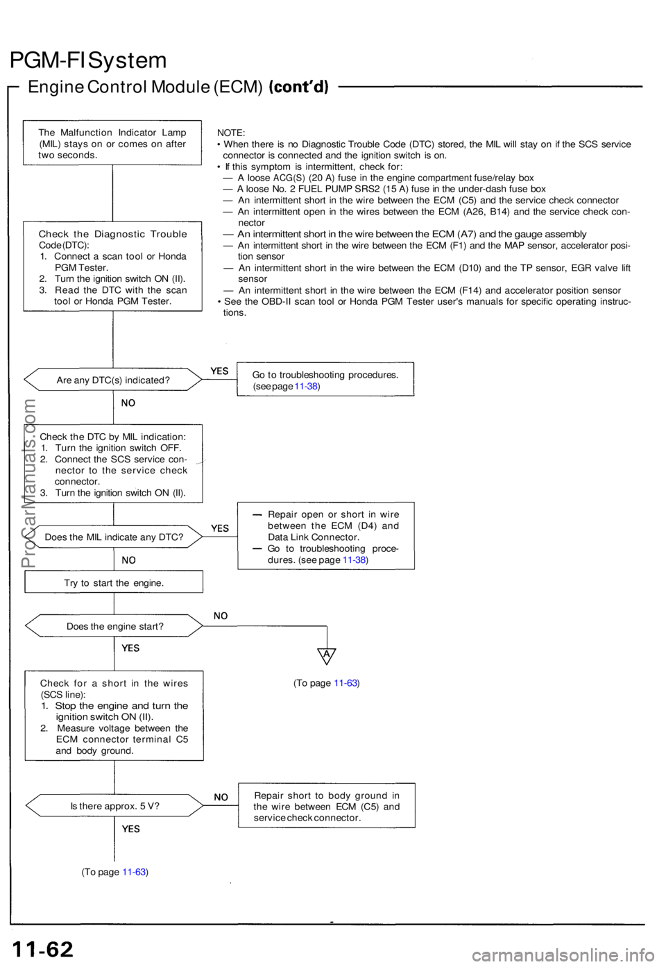
PGM-FI Syste m
Engine Contro l Modul e (ECM )
The Malfunctio n Indicato r Lam p
(MIL ) stay s o n o r come s o n afte r
tw o seconds .
Check th e Diagnosti c Troubl eCode (DTC) :
1 . Connec t a sca n too l o r Hond a
PG M Tester .
2 . Tur n th e ignitio n switc h O N (II) .
3 . Rea d th e DT C wit h th e sca n
too l o r Hond a PG M Tester .
NOTE:• Whe n ther e is n o Diagnosti c Troubl e Cod e (DTC ) stored , th e MI L wil l sta y o n i f th e SC S servic e
connecto r i s connecte d an d th e ignitio n switc h i s on .
• I f thi s sympto m is intermittent , chec k for :
— A loos e ACG(S ) (20 A ) fus e in th e engin e compartment fuse/rela y box— A loos e No . 2 FUE L PUM P SRS 2 (1 5 A ) fus e in th e under-das h fus e bo x
— A n intermitten t shor t i n th e wir e betwee n th e EC M (C5 ) an d th e servic e chec k connecto r
— A n intermitten t ope n i n th e wire s betwee n th e EC M (A26 , B14 ) an d th e servic e chec k con -
necto r
— A n intermitten t shor t i n th e wir e betwee n th e EC M (A7 ) an d th e gaug e assembl y— A n intermitten t shor t i n th e wir e betwee n th e EC M (F1 ) an d th e MA P sensor , accelerato r posi -
tio n senso r
— A n intermitten t shor t i n th e wir e betwee n th e EC M (D10 ) an d th e T P sensor , EG R valv e lif t
senso r— A n intermitten t shor t i n th e wir e betwee n th e EC M (F14 ) an d accelerato r positio n senso r
• Se e th e OBD-I I sca n too l o r Hond a PG M Teste r user' s manual s fo r specifi c operatin g instruc -
tions .
Ar e an y DTC(s ) indicated ? G
o to troubleshootin g procedures .
(se e pag e 11-38 )
Chec k th e DT C b y MI L indication :
1 . Tur n th e ignitio n switc h OFF .
2 . Connec t th e SC S servic e con -
necto r t o th e servic e chec k
connector .
3 . Tur n th e ignitio n switc h O N (II) .
Doe s th e MI L indicat e an y DTC ? Repai
r ope n o r shor t i n wir e
betwee n th e EC M (D4 ) an d
Dat a Lin k Connector .
G o t o troubleshootin g proce -
dures . (se e pag e 11-38 )
Tr y t o star t th e engine .
Doe s th e engin e start ?
Chec k fo r a shor t i n th e wire s
(SC S line) :
1. Sto p th e engin e an d tur n th eignitio n switc h O N (II) .2. Measur e voltag e betwee n th e
EC M connecto r termina l C 5
an d bod y ground . (T
o pag e 11-63 )
I s ther e approx . 5 V ?
(T o pag e 11-63 ) Repai
r shor t t o bod y groun d i n
th e wir e betwee n EC M (C5 ) an d
servic e chec k connector .
ProCarManuals.com
Page 232 of 1640
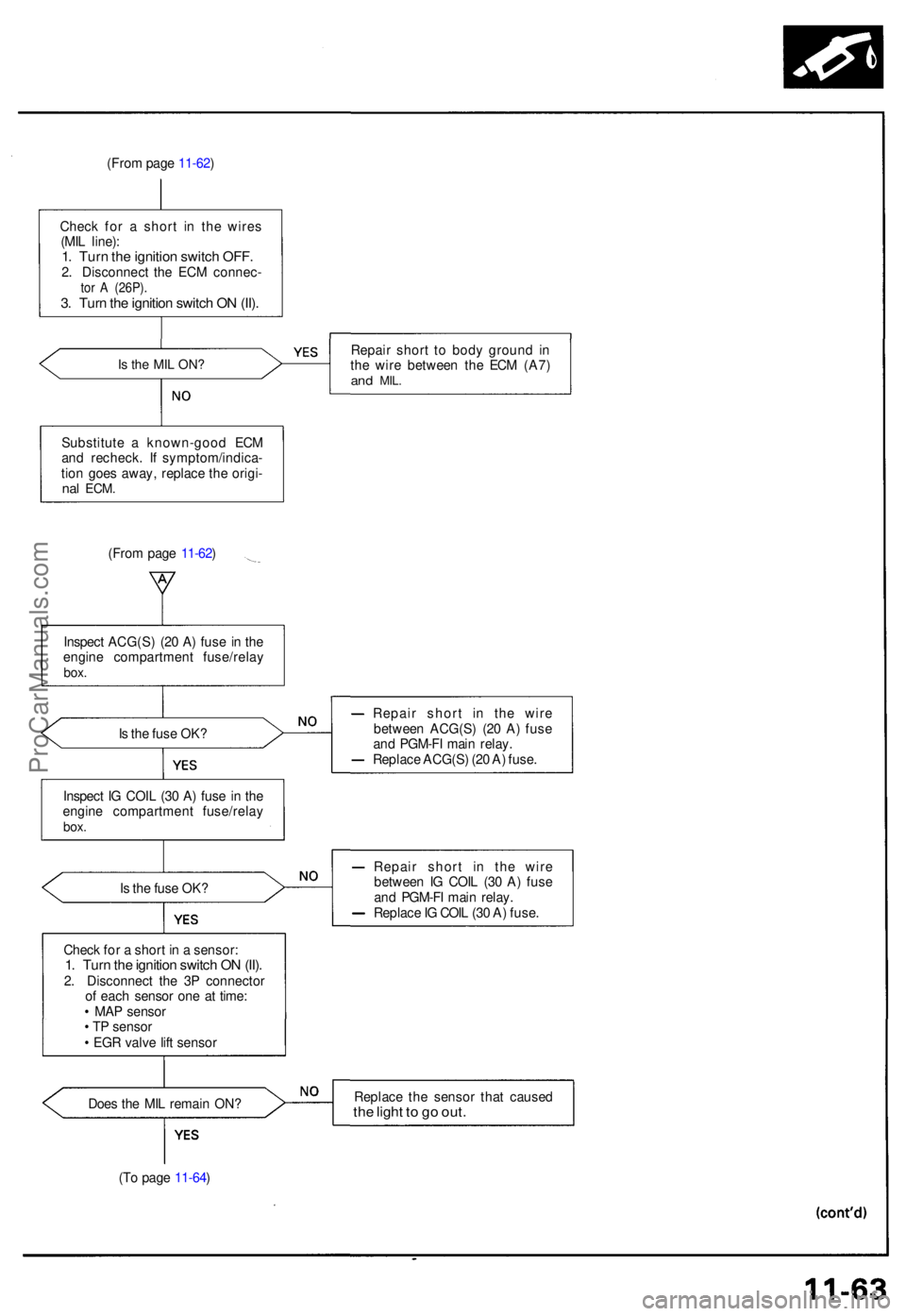
(From pag e 11-62 )
Chec k fo r a shor t i n th e wire s
(MI L line) :
1. Tur n th e ignitio n switc h OFF .2. Disconnec t th e EC M connec -tor A (26P) .3. Tur n th e ignitio n switc h O N (II) .
Is th e MI L ON ?Repai r shor t t o bod y groun d i n
th e wir e betwee n th e EC M (A7 )
and MIL .
Substitut e a known-goo d EC M
an d recheck . I f symptom/indica -
tio n goe s away , replac e th e origi -
nal ECM .
(From pag e 11-62 )
Inspec t ACG(S ) (2 0 A ) fus e i n th e
engin e compartmen t fuse/rela y
box.
Is th e fus e OK ? Repai
r shor t i n th e wir e
betwee n ACG(S ) (2 0 A ) fus e
an d PGM-F I mai n relay .
Replac e ACG(S ) (2 0 A ) fuse .
Inspec t I G COI L (3 0 A ) fus e i n th e
engin e compartmen t fuse/rela y
box.
Is th e fus e OK ? Repai
r shor t i n th e wir e
betwee n I G COI L (3 0 A ) fus e
an d PGM-F I mai n relay .
Replac e IG COI L (3 0 A ) fuse .
Chec k fo r a shor t i n a sensor :
1. Tur n th e ignitio n switc h O N (II) .2. Disconnec t th e 3 P connecto r
o f eac h senso r on e a t time :
• MA P senso r
• T P senso r
• EG R valv e lif t senso r
Doe s th e MI L remai n ON ? Replac
e th e senso r tha t cause d
the ligh t t o g o out .
(To pag e 11-64 )
ProCarManuals.com
Page 233 of 1640
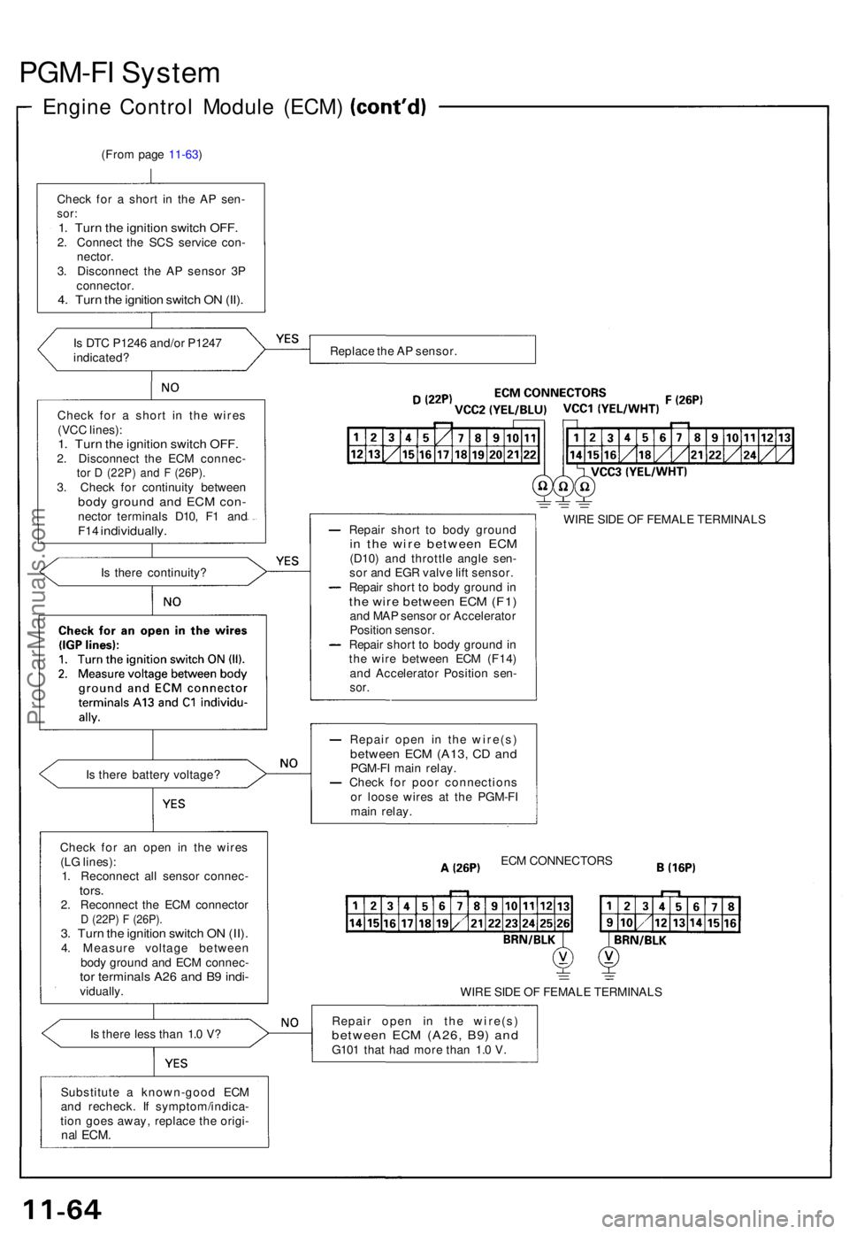
PGM-FI Syste m
Engine Contro l Modul e (ECM )
(From pag e 11-63 )
Chec k fo r a shor t i n th e A P sen -
sor:1. Tur n th e ignitio n switc h OFF .2. Connec t th e SC S servic e con -
nector .
3 . Disconnec t th e A P senso r 3 P
connector .
4. Tur n th e ignitio n switc h O N (II) .
Is DT C P124 6 and/o r P124 7
indicated ?
Chec k fo r a shor t i n th e wire s
(VC C lines) :
1. Tur n th e ignitio n switc h OFF .2. Disconnec t th e EC M connec -tor D (22P ) an d F (26P) .3. Chec k fo r continuit y betwee nbody groun d an d EC M con -necto r terminal s D10 , F 1 an dF14 individually .
Is ther e continuity ?
I s ther e batter y voltage ?
Chec k fo r a n ope n i n th e wire s
(L G lines) :
1 . Reconnec t al l senso r connec -
tors.2. Reconnec t th e EC M connecto rD (22P ) F (26P) .3. Tur n th e ignitio n switc h O N (II) .4. Measur e voltag e betwee n
bod y groun d an d EC M connec -
tor terminal s A2 6 an d B 9 indi -vidually .
I s ther e les s tha n 1. 0 V ?
Substitut e a known-goo d EC M
an d recheck . I f symptom/indica -
tio n goe s away , replac e th e origi -
nal ECM .
Replac e th e A P sensor .
Repai r shor t t o bod y groun d
in th e wir e betwee n EC M(D10 ) an d throttl e angl e sen -
so r an d EG R valv e lif t sensor .
Repai r shor t t o bod y groun d in
th e wir e betwee n EC M (F1 )and MA P senso r o r Accelerato r
Positio n sensor .
Repai r shor t t o bod y groun d in
th e wir e betwee n EC M (F14 )
an d Accelerato r Positio n sen -
sor.
WIR E SID E O F FEMAL E TERMINAL S
Repai r ope n i n th e wire(s )
between EC M (A13 , C D an dPGM-F I mai n relay .
Chec k fo r poo r connection s
o r loos e wire s a t th e PGM-F I
mai n relay .
ECM CONNECTOR S
WIR E SID E O F FEMAL E TERMINAL S
Repai r ope n i n th e wire(s )
between EC M (A26 , B9 ) an dG10 1 tha t ha d mor e tha n 1. 0 V .
ProCarManuals.com
Page 234 of 1640
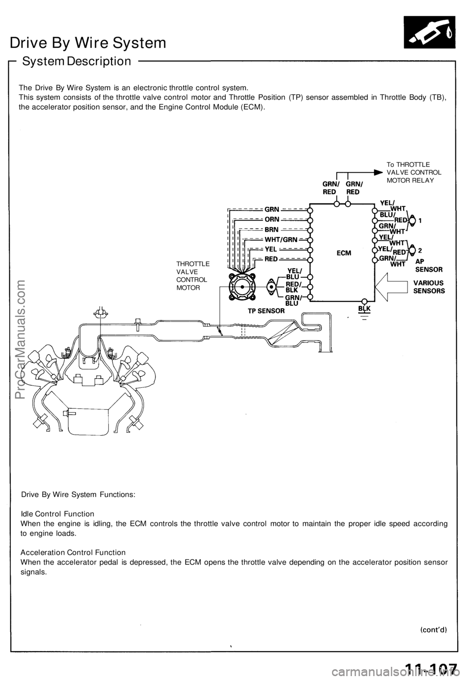
Drive By Wire System
System Description
The Drive By Wire System is an electronic throttle control system.
This system consists of the throttle valve control motor and Throttle Position (TP) sensor assembled in Throttle Body (TB),
the accelerator position sensor, and the Engine Control Module (ECM).
To THROTTLE
VALVE CONTROL
MOTOR RELAY
THROTTLE
VALVE
CONTROL
MOTOR
Drive By Wire System Functions:
Idle Control Function
When the engine is idling, the ECM controls the throttle valve control motor to maintain the proper idle speed according
to engine loads.
Acceleration Control Function
When the accelerator pedal is depressed, the ECM opens the throttle valve depending on the accelerator position sensor
signals.ProCarManuals.com
Page 235 of 1640
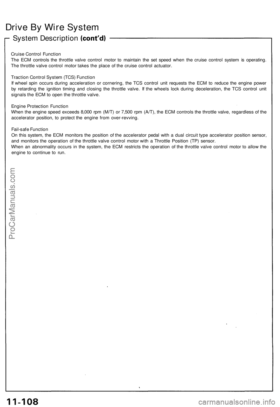
Drive B y Wir e Syste m
System Descriptio n
Cruise Contro l Functio n
Th e EC M control s th e throttl e valv e contro l moto r t o maintai n th e se t spee d whe n th e cruis e contro l syste m is operating .
Th e throttl e valv e contro l moto r take s th e plac e o f th e cruis e contro l actuator .
Tractio n Contro l Syste m (TCS ) Functio n
I f whee l spi n occur s durin g acceleratio n o r cornering , th e TC S contro l uni t request s th e EC M to reduc e th e engin e powe r
b y retardin g th e ignitio n timin g an d closin g th e throttl e valve . I f th e wheel s loc k during deceleration , th e TC S contro l uni t
signal s th e EC M to ope n th e throttl e valve .
Engin e Protectio n Functio n
Whe n th e engin e spee d exceed s 8,00 0 rp m (M/T ) o r 7,50 0 rp m (A/T) , th e EC M control s th e throttl e valve , regardles s o f th e
accelerato r position , t o protec t th e engin e fro m over-revving .
Fail-saf e Functio n
O n thi s system , th e EC M monitor s th e positio n o f th e accelerato r peda l wit h a dua l circui t typ e accelerato r positio n sensor ,
an d monitor s th e operatio n o f th e throttl e valv e contro l moto r wit h a Throttl e Positio n (TP ) sensor .
Whe n a n abnormalit y occur s i n th e system , th e EC M restrict s th e operatio n o f th e throttl e valv e contro l moto r t o allo w th e
engin e t o continu e t o run .
ProCarManuals.com
Page 236 of 1640
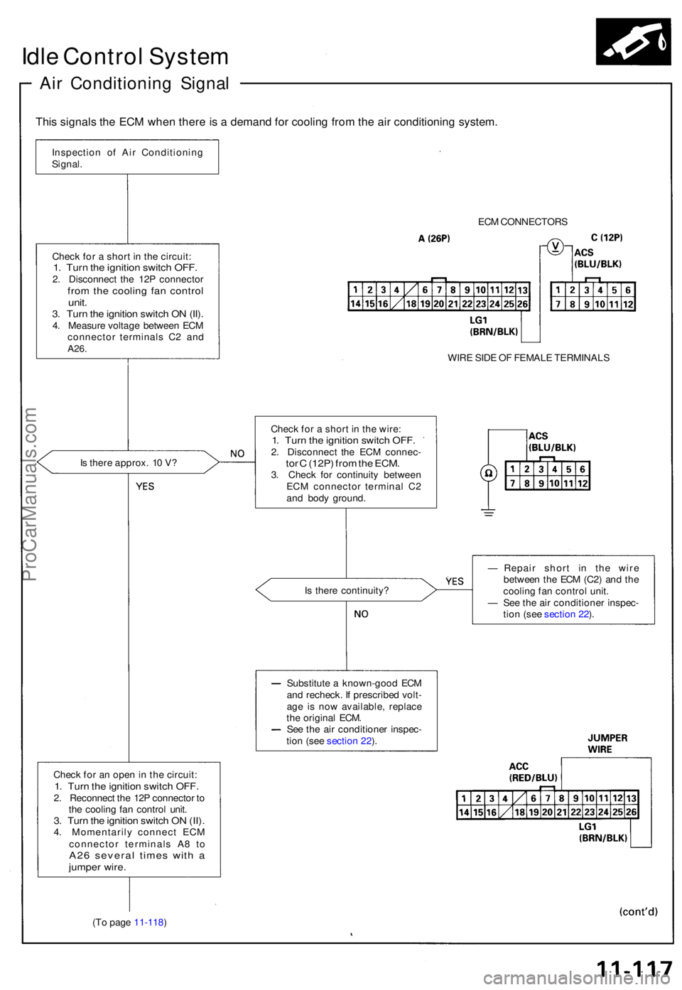
Idle Contro l Syste m
Air Conditionin g Signa l
This signal s th e EC M whe n ther e is a deman d fo r coolin g fro m th e ai r conditionin g system .
Inspectio n o f Ai r Conditionin g
Signal .
ECM CONNECTOR S
Chec k fo r a shor t i n th e circuit :
1. Tur n th e ignitio n switc h OFF .2. Disconnec t th e 12 P connecto rfrom th e coolin g fa n contro lunit.3. Tur n th e ignitio n switc h O N (II) .4. Measur e voltag e betwee n EC M
connecto r terminal s C 2 an d
A26 .WIR E SID E O F FEMAL E TERMINAL S
I s ther e approx . 1 0 V ? Chec
k fo r a shor t i n th e wire :
1. Tur n th e ignitio n switc h OFF .2. Disconnec t th e EC M connec -tor C (12P ) fro m th e ECM .3. Chec k fo r continuit y betwee n
EC M connecto r termina l C 2
an d bod y ground .
I s ther e continuity ? —
Repai r shor t i n th e wir e
betwee n th e EC M (C2 ) an d th e
coolin g fa n contro l unit .
— Se e th e ai r conditione r inspec -
tio n (se e sectio n 22 ).
Substitut e a known-goo d EC M
an d recheck . I f prescribe d volt -
ag e i s no w available , replac e
th e origina l ECM .
Se e th e ai r conditione r inspec -
tio n (se e sectio n 22 ).
Chec k fo r a n ope n in th e circuit :
1. Tur n th e ignitio n switc h OFF .2. Reconnec t th e 12 P connecto r t o
th e coolin g fa n contro l unit .
3. Tur n th e ignitio n switc h O N (II) .4. Momentaril y connec t EC M
connecto r terminal s A 8 t o
A2 6 severa l time s wit h ajumpe r wire .
(To pag e 11-118 )
ProCarManuals.com
Page 237 of 1640
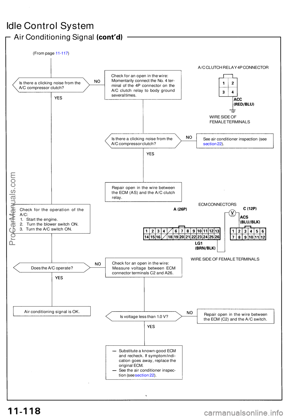
Idle Contro l Syste m
Air Conditionin g Signa l
(From pag e 11-117 )
I s ther e a clickin g nois e fro m th e
A/ C compresso r clutch ?
Chec k fo r th e operatio n o f th e
A/C :1. Star t th e engine .
2 . Tur n th e blowe r switc h ON .
3 . Tur n th e A/ C switc h ON .
Doe s th e A/ C operate ?
Ai r conditionin g signa l i s OK . A/
C CLUTC H RELA Y 4P CONNECTO R
Chec k fo r a n ope n in th e wire :
Momentaril y connec t th e No . 4 ter -
mina l o f th e 4 P connecto r o n th e
A/ C clutc h rela y t o bod y groun d
severa l times .
WIRE SID E O F
FEMAL E TERMINAL S
I s ther e a clickin g nois e fro m th e
A/ C compresso r clutch ? Se
e ai r conditione r inspectio n (se e
sectio n 22 ).
Repai r ope n in th e wir e betwee n
th e EC M (AS ) an d th e A/ C clutc h
relay.
ECM CONNECTOR S
Chec k fo r a n ope n in th e wire :
Measur e voltag e betwee n EC M
connecto r terminal s C 2 an d A26 . WIR
E SID E O F FEMAL E TERMINAL S
I s voltag e les s tha n 1. 0 V ? Repai
r ope n in th e wir e betwee n
th e EC M (C2 ) an d th e A/ C switch .
Substitut e a known-goo d EC M
an d recheck . I f symptom/indi -
catio n goe s away , replac e th e
origina l ECM .
Se e th e ai r conditione r inspec -
tio n (se e sectio n 22 ).
ProCarManuals.com
Page 238 of 1640
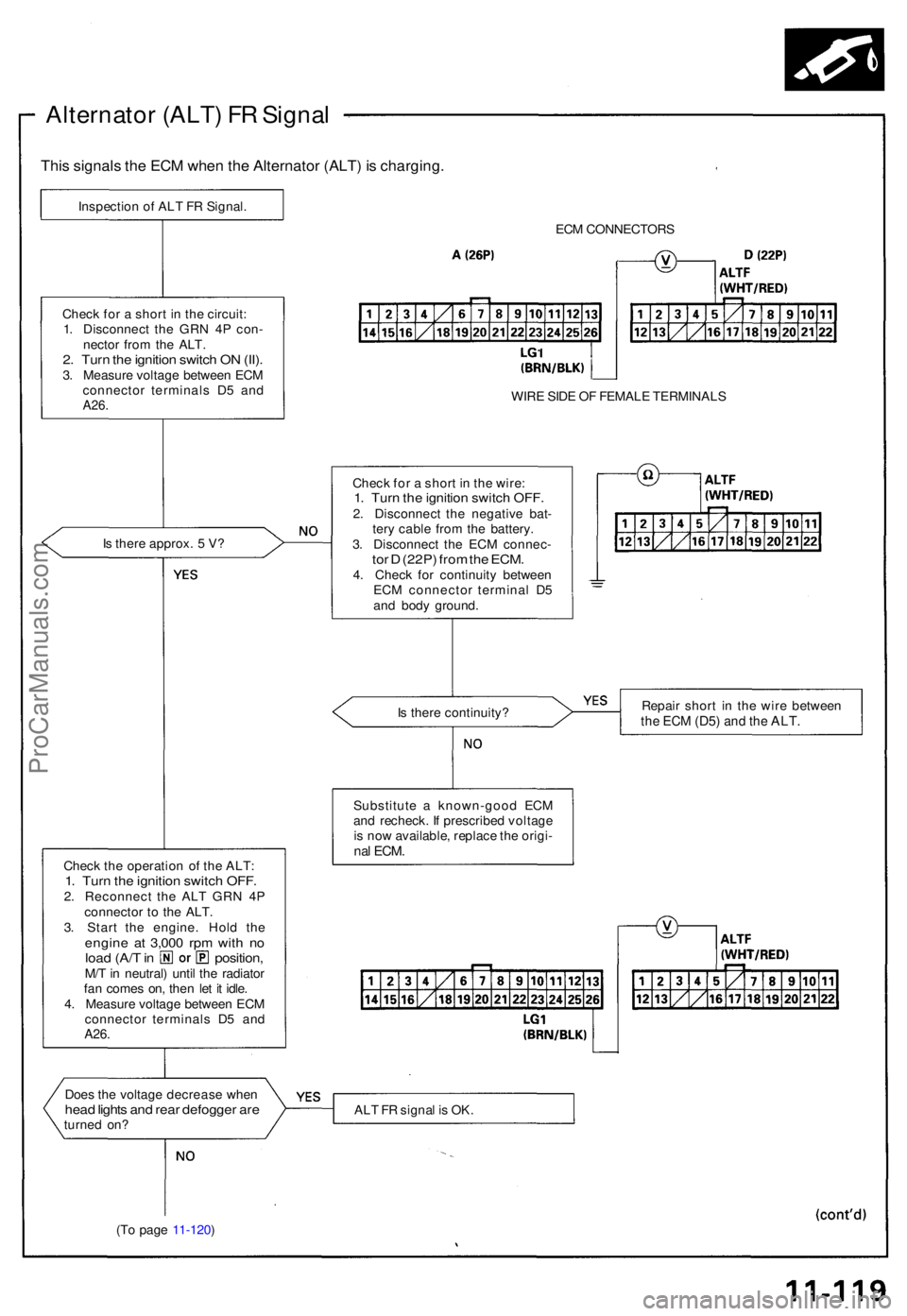
Alternator (ALT ) F R Signa l
This signal s th e EC M whe n th e Alternato r (ALT ) i s charging .
Inspection o f AL T F R Signal .
ECM CONNECTOR S
WIR E SID E O F FEMAL E TERMINAL S
Chec k fo r a shor t i n th e wire :
1. Tur n th e ignitio n switc h OFF .2. Disconnec t th e negativ e bat -
ter y cabl e fro m th e battery .
3 . Disconnec t th e EC M connec -
tor D (22P ) fro m th e ECM .4. Chec k fo r continuit y betwee n
EC M connecto r termina l D 5
an d bod y ground .
I
s ther e approx . 5 V ?
Chec
k fo r a shor t i n th e circuit :
1 . Disconnec t th e GR N 4 P con -
necto r fro m th e ALT .
2. Tur n th e ignitio n switc h O N (II) .3. Measur e voltag e betwee n EC M
connecto r terminal s D 5 an d
A26 .
Is ther e continuity ? Repai
r shor t i n th e wir e betwee nthe EC M (D5 ) and th e ALT .
Substitut e a known-goo d EC M
an d recheck . I f prescribe d voltag e
i s no w available , replac e th e origi -
nal ECM .Chec k th e operatio n o f th e ALT :1. Tur n th e ignitio n switc h OFF .2. Reconnec t th e AL T GR N 4 P
connecto r t o th e ALT .
3 . Star t th e engine . Hol d th e
engin e a t 3,00 0 rp m wit h n oloa d (A/ T in position ,M/T in neutral ) unti l th e radiato r
fa n come s on , the n le t i t idle .
4 . Measur e voltag e betwee n EC M
connecto r terminal s D 5 an d
A26.
Doe s th e voltag e decreas e whe nhead light s an d rea r defogge r ar eturne d on ? AL
T F R signa l i s OK .
(T o pag e 11-120 )
ProCarManuals.com
Page 239 of 1640
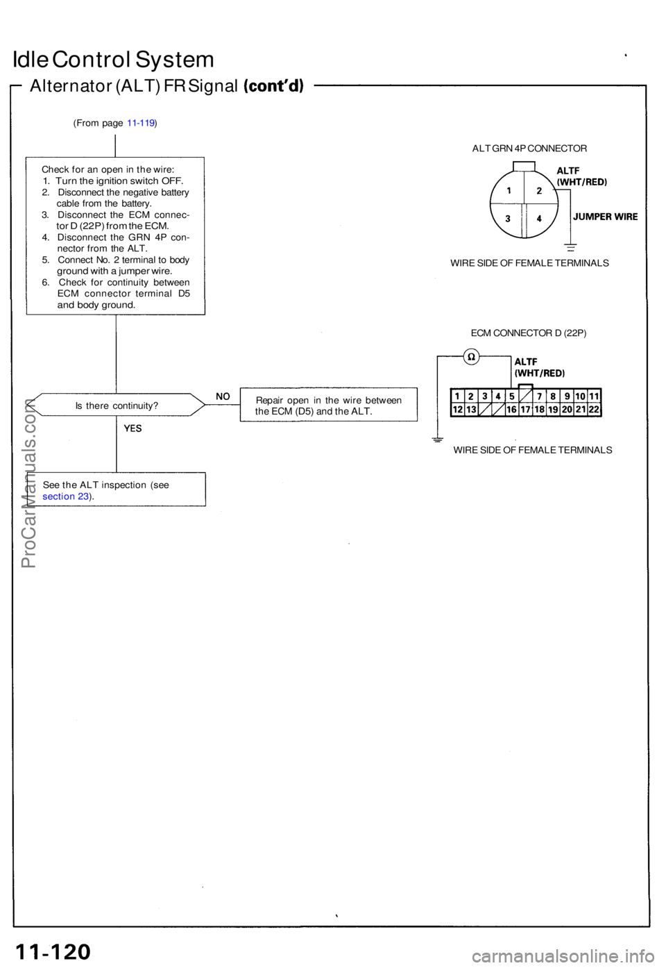
Idle Contro l Syste m
Alternato r (ALT ) F R Signa l
(From pag e 11-119 )
ALT GR N 4P CONNECTO R
Chec k fo r a n ope n in th e wire :
1. Tur n th e ignitio n switc h OFF .2. Disconnec t th e negativ e batter y
cabl e fro m th e battery .
3 . Disconnec t th e EC M connec -
tor D (22P ) fro m th e ECM .4. Disconnec t th e GR N 4 P con -
necto r fro m th e ALT .
5 . Connec t No . 2 termina l t o bod y
groun d wit h a jumpe r wire .6. Chec k fo r continuit y betwee n
EC M connecto r termina l D 5
and bod y ground .
WIRE SID E O F FEMAL E TERMINAL S
EC M CONNECTO R D (22P )
I s ther e continuity ? Repai
r ope n i n th e wir e betwee n
the EC M (D5 ) and th e ALT .
WIRE SID E O F FEMAL E TERMINAL S
Se e th e AL T inspectio n (se e
sectio n 23 ).
ProCarManuals.com
Page 240 of 1640
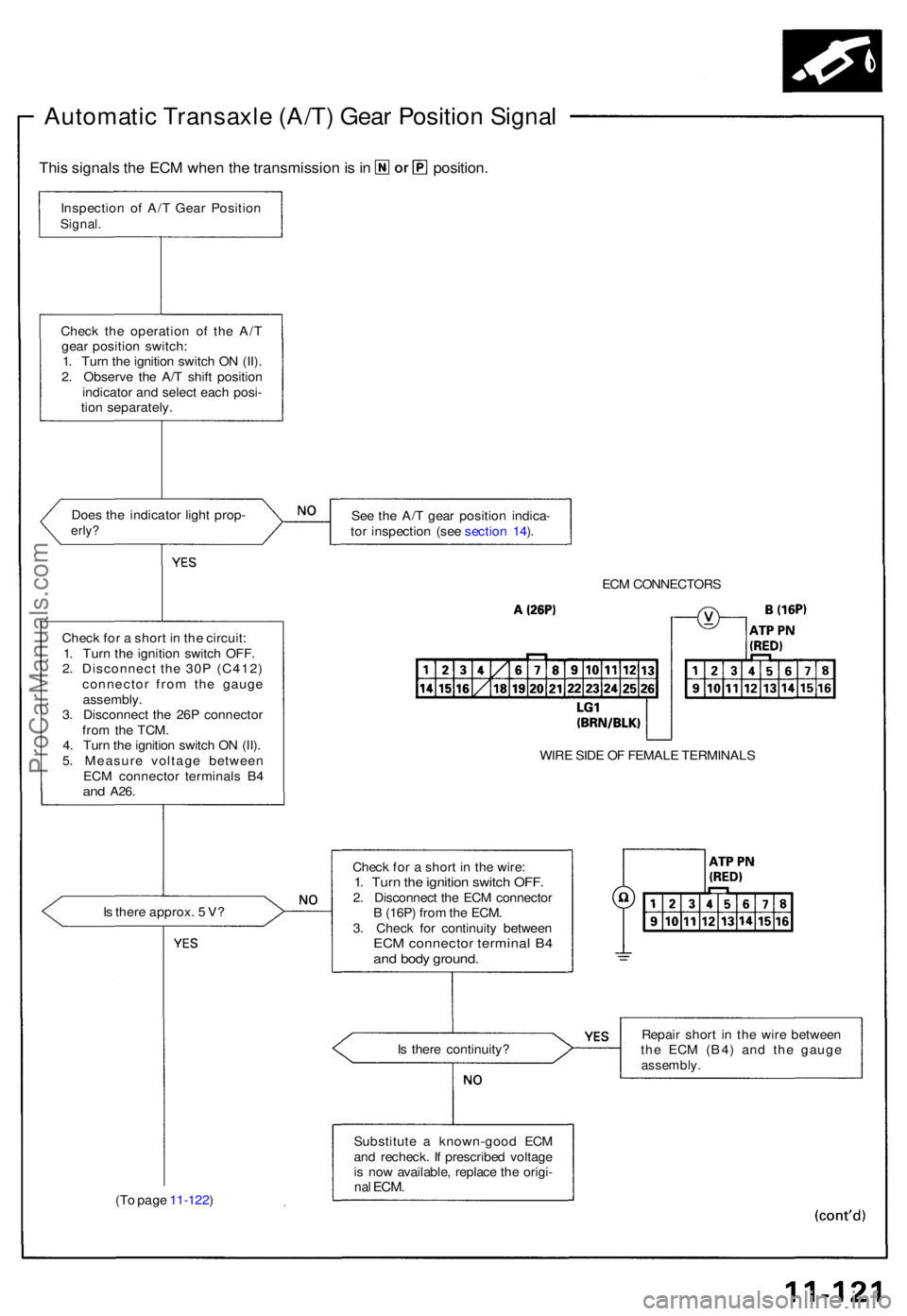
Inspection o f A/ T Gea r Positio nSignal.
This signal s th e EC M whe n th e transmissio n is in position.
Automati c Transaxl e (A/T ) Gea r Positio n Signa l
Check th e operatio n o f th e A/ T
gea r positio n switch :
1 . Tur n th e ignitio n switc h O N (II) .
2 . Observ e th e A/ T shif t positio n
indicato r an d selec t eac h posi -
tio n separately .
Doe s th e indicato r ligh t prop -
erly?See th e A/ T gea r positio n indica -
to r inspectio n (se e sectio n 14 ).
ECM CONNECTOR S
WIR E SID E O F FEMAL E TERMINAL S
Chec k fo r a shor t i n th e wire :
1. Tur n th e ignitio n switc h OFF .2. Disconnec t th e EC M connecto r
B (16P ) fro m th e ECM .
3 . Chec k fo r continuit y betwee n
ECM connecto r termina l B 4an d bod y ground .
Is ther e approx . 5 V ?
Chec
k fo r a shor t i n th e circuit :
1 . Tur n th e ignitio n switc h OFF .
2 . Disconnec t th e 30 P (C412 )
connecto r fro m th e gaug e
assembly .
3 . Disconnec t th e 26 P connecto r
fro m th e TCM .
4 . Tur n th e ignitio n switc h O N (II) .
5 . Measur e voltag e betwee n
EC M connecto r terminal s B 4
and A26 .
Is ther e continuity ? Repai
r shor t i n th e wir e betwee n
th e EC M (B4 ) an d th e gaug eassembly .
Substitute a known-goo d EC M
an d recheck . I f prescribe d voltag e
i s no w available , replac e th e origi -
nal ECM .(To pag e 11-122 )
ProCarManuals.com