ACURA NSX 1991 Service Repair Manual
Manufacturer: ACURA, Model Year: 1991, Model line: NSX, Model: ACURA NSX 1991Pages: 1640, PDF Size: 60.48 MB
Page 251 of 1640
Fuel Suppl y Syste m
Fuel Pressur e
Relieving
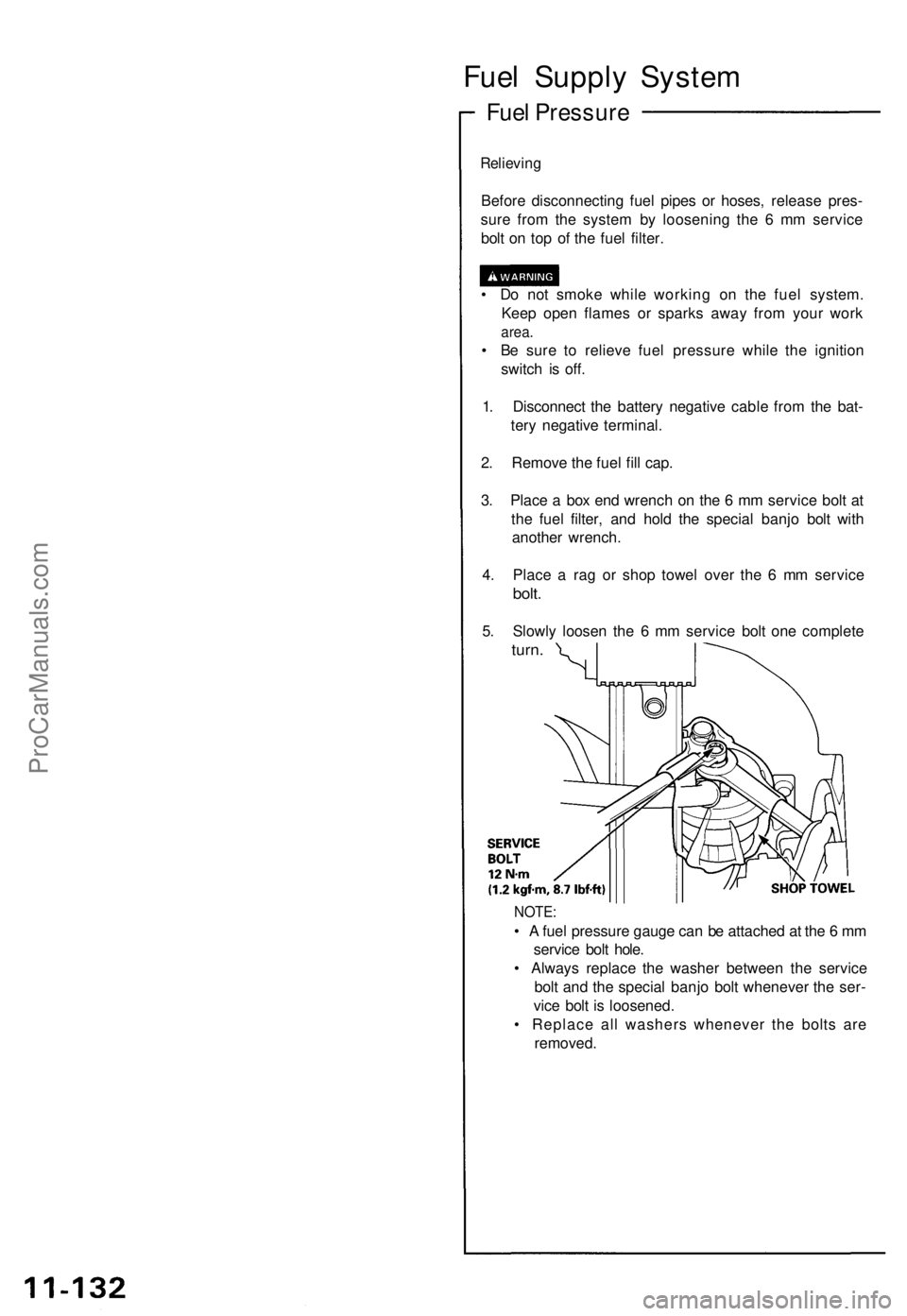
Before disconnectin g fue l pipe s o r hoses , releas e pres -
sur e fro m th e syste m b y loosenin g th e 6 m m servic e
bol t o n to p o f th e fue l filter .
• D o no t smok e whil e workin g o n th e fue l system .
Kee p ope n flame s o r spark s awa y fro m you r wor k
area.
• B e sur e t o reliev e fue l pressur e whil e th e ignitio n
switc h i s off .
1 . Disconnec t th e batter y negativ e cabl e fro m th e bat -
ter y negativ e terminal .
2 . Remov e th e fue l fil l cap .
3 . Plac e a bo x en d wrenc h o n th e 6 m m servic e bol t a t
th e fue l filter , an d hol d th e specia l banj o bol t wit h
anothe r wrench .
4 . Plac e a ra g o r sho p towe l ove r th e 6 m m servic e
bolt.
5. Slowl y loose n th e 6 m m servic e bol t on e complet e
turn.
NOTE :
• A fue l pressur e gaug e ca n b e attache d a t th e 6 m m
servic e bol t hole .
• Alway s replac e th e washe r betwee n th e servic e
bol t an d th e specia l banj o bol t wheneve r th e ser -
vic e bol t i s loosened .
• Replac e al l washer s wheneve r th e bolt s ar e
removed .
ProCarManuals.com
Page 252 of 1640
Inspection
1 . Reliev e fue l pressur e (se e pag e 11-132 )
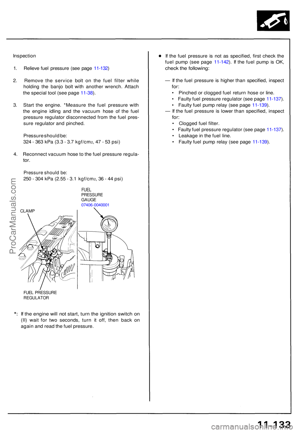
2 . Remov e th e servic e bol t o n th e fue l filte r whil e
holdin g th e banj o bol t wit h anothe r wrench . Attac h
th e specia l too l (se e pag e 11-38 ).
3 . Star t th e engine . *Measur e th e fue l pressur e wit h
th e engin e idlin g an d th e vacuu m hos e o f th e fue l
pressur e regulato r disconnecte d fro m th e fue l pres -
sur e regulato r an d pinched .
Pressur e shoul d be :
32 4 - 36 3 kP a (3. 3 - 3. 7 kgf/cm
2, 4 7 - 5 3 psi )
4 . Reconnec t vacuu m hos e to th e fue l pressur e regula -
tor.
Pressur e shoul d be :
250 - 30 4 kP a (2.5 5 - 3. 1 kgf/cm2, 3 6 - 4 4 psi )
FUE LPRESSUR EGAUGE07406-004000 1
CLAMP
FUEL PRESSUR EREGULATO R
If th e engin e wil l no t start , tur n th e ignitio n switc h o n
(II ) wai t fo r tw o seconds , tur n i t off , the n bac k o n
agai n an d rea d th e fue l pressure . I
f th e fue l pressur e i s no t a s specified , firs t chec k th e
fue l pum p (se e pag e 11-142 ). I f th e fue l pum p i s OK ,
chec k th e following :
— If th e fue l pressur e is highe r tha n specified , inspec t
for:
• Pinche d o r clogge d fue l retur n hos e o r line .
• Fault y fue l pressur e regulato r (se e pag e 11-137 ).
• Fault y fue l pum p rela y (se e pag e 11-139 ).
— If th e fue l pressur e is lowe r tha n specified , inspec t
for:
• Clogge d fue l filter .
• Fault y fue l pressur e regulato r (se e pag e 11-137 ).
• Leakage in th e fue l line .
• Fault y fue l pum p rela y (se e pag e 11-139 ).
ProCarManuals.com
Page 253 of 1640
Fuel Suppl y Syste m
Fuel Injector s
Replacemen t
Do no t smok e durin g th e work . Kee p ope n flame s awa y fro m you r wor k area .
1 . Reliev e fue l pressur e (se e pag e 11-132 ).
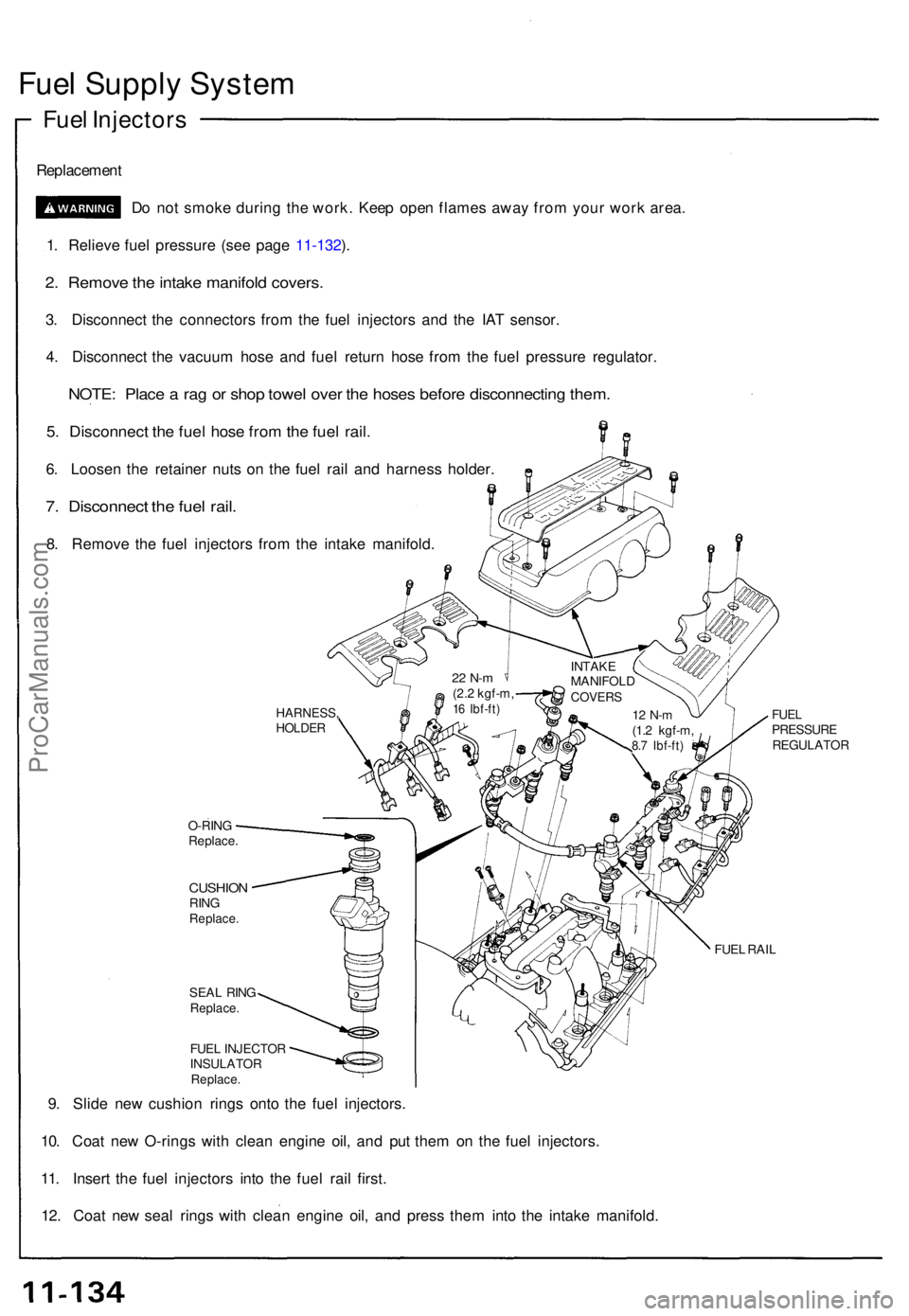
2 . Remov e th e intak e manifol d covers .
3. Disconnec t th e connector s fro m th e fue l injector s an d th e IA T sensor .
4 . Disconnec t th e vacuu m hos e an d fue l retur n hos e fro m th e fue l pressur e regulator .
NOTE: Plac e a ra g o r sho p towe l ove r th e hose s befor e disconnectin g them .
5. Disconnec t th e fue l hos e fro m th e fue l rail .
6. Loose n th e retaine r nut s o n th e fue l rai l an d harnes s holder .
7. Disconnec t th e fue l rail .
8. Remov e th e fue l injector s fro m th e intak e manifold .
O-RINGReplace .
CUSHIONRINGReplace .
SEAL RIN GReplace .
FUEL INJECTO R
INSULATO R
Replace.
9. Slid e ne w cushio n ring s ont o th e fue l injectors .
10 . Coa t ne w O-ring s wit h clea n engin e oil , an d pu t the m o n th e fue l injectors .
11 . Inser t th e fue l injector s int o th e fue l rai l first .
12 . Coa t ne w sea l ring s wit h clea n engin e oil , an d pres s the m int o th e intak e manifold .
FUELPRESSUR EREGULATO R
FUEL RAI L
HARNESS ,HOLDER
22 N- m(2.2 kgf-m ,16 Ibf-ft )
INTAK E
MANIFOL D
COVERS
12 N- m(1.2 kgf-m ,8.7 Ibf-ft )
ProCarManuals.com
Page 254 of 1640
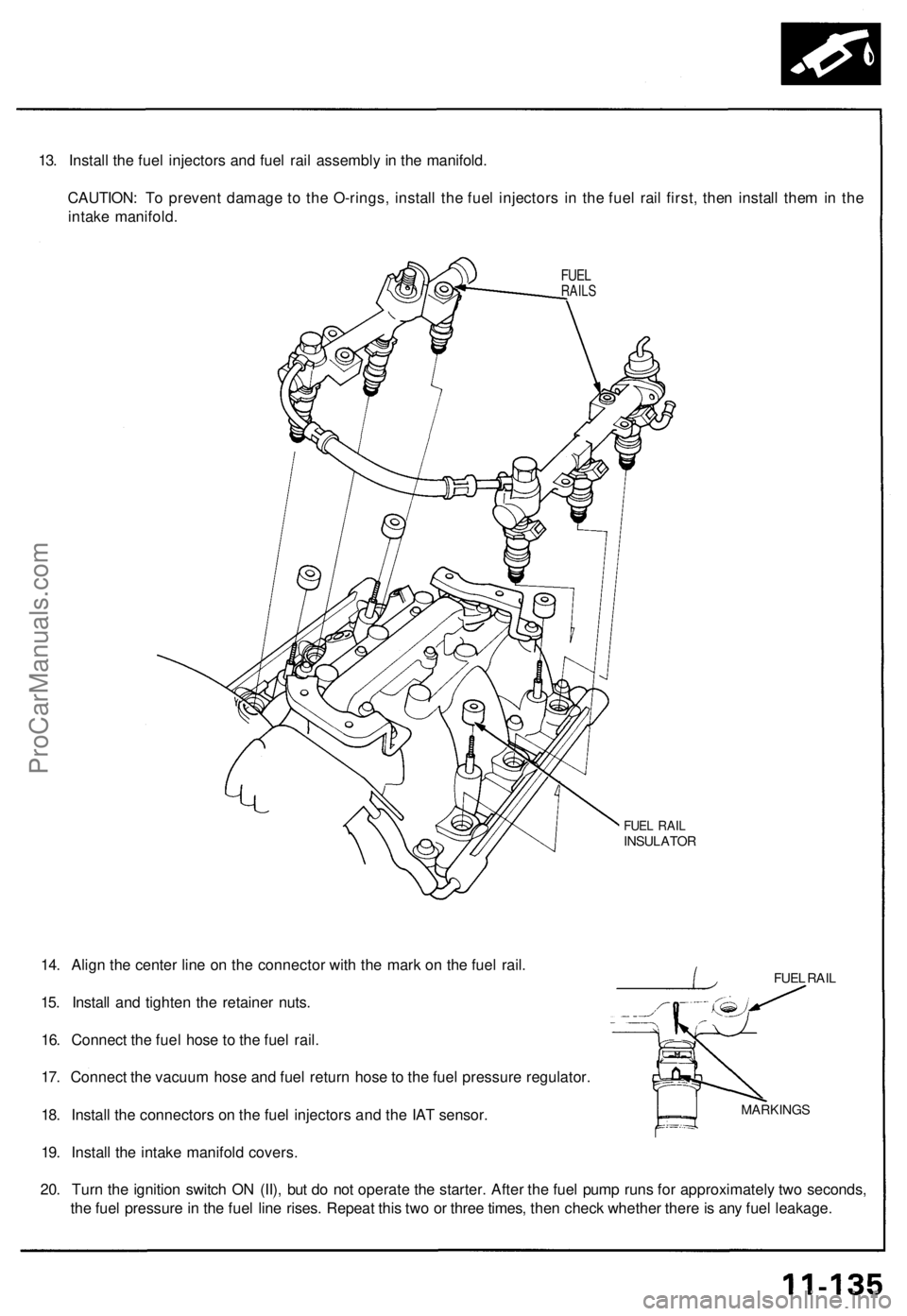
13. Install the fuel injectors and fuel rail assembly in the manifold.
CAUTION: To prevent damage to the O-rings, install the fuel injectors in the fuel rail first, then install them in the
intake manifold.
FUEL
RAILS
FUEL RAIL
INSULATOR
FUEL RAIL
14. Align the center line on the connector with the mark on the fuel rail.
15. Install and tighten the retainer nuts.
16. Connect the fuel hose to the fuel rail.
17. Connect the vacuum hose and fuel return hose to the fuel pressure regulator.
18. Install the connectors on the fuel injectors and the IAT sensor.
19. Install the intake manifold covers.
20. Turn the ignition switch ON (II), but do not operate the starter. After the fuel pump runs for approximately two seconds,
the fuel pressure in the fuel line rises. Repeat this two or three times, then check whether there is any fuel leakage.
MARKINGSProCarManuals.com
Page 255 of 1640
Fuel Supply System
Fuel Injector Resistor
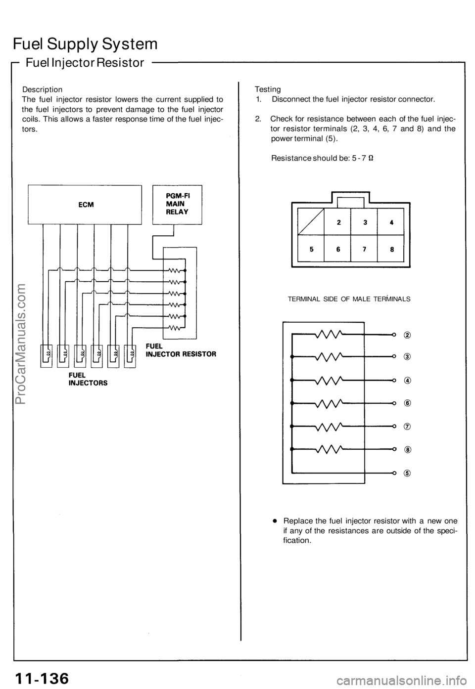
Description
The fuel injector resistor lowers the current supplied to
the fuel injectors to prevent damage to the fuel injector
coils. This allows a faster response time of the fuel injec-
tors.
Testing
1. Disconnect the fuel injector resistor connector.
2. Check for resistance between each of the fuel injec-
tor resistor terminals (2, 3, 4, 6, 7 and 8) and the
power terminal (5).
Resistance should be: 5 - 7
TERMINAL SIDE OF MALE TERMINALS
Replace the fuel injector resistor with a new one
if any of the resistances are outside of the speci-
fication.ProCarManuals.com
Page 256 of 1640
Fuel Pressur e Regulato r
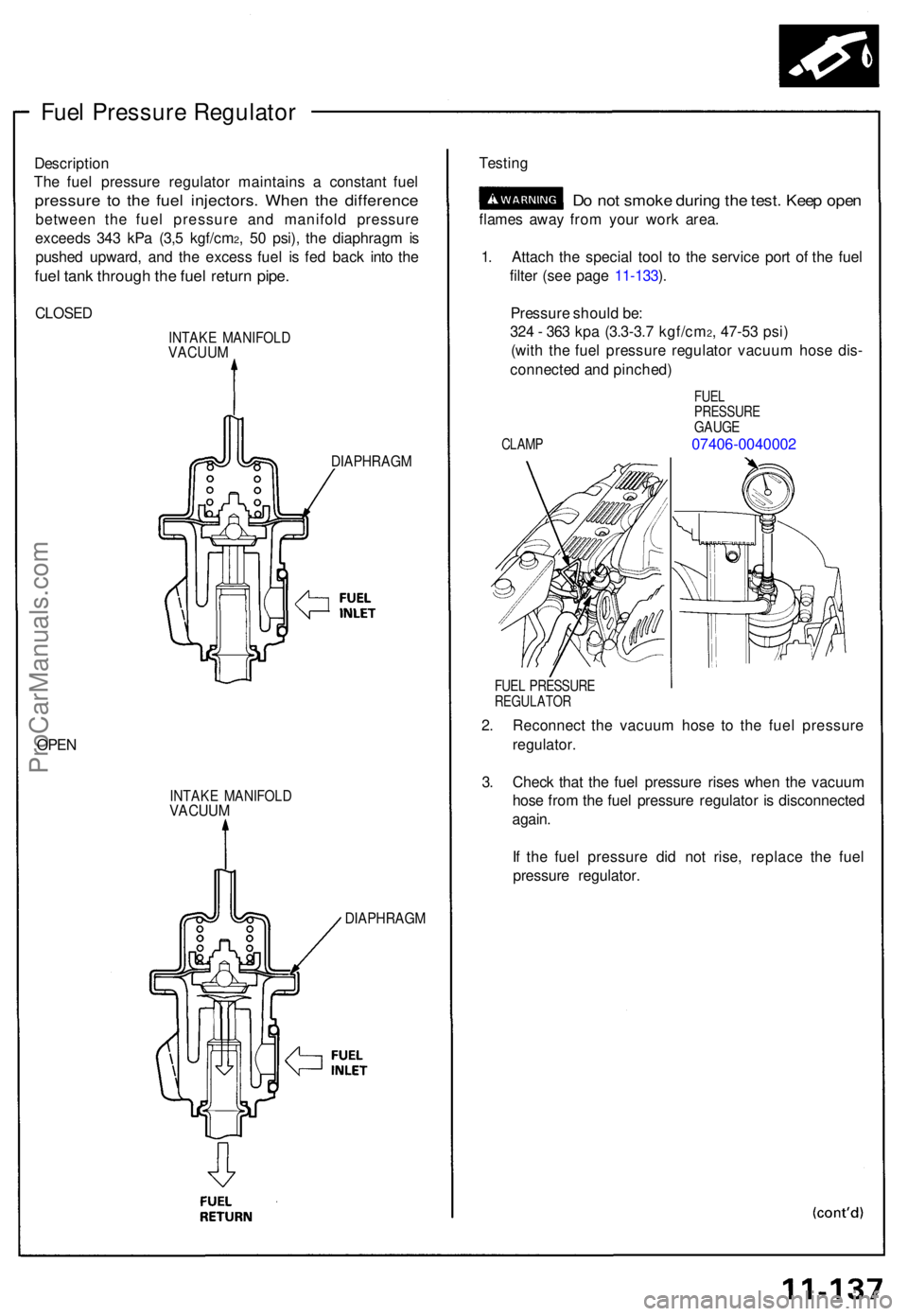
Descriptio n
Th e fue l pressur e regulato r maintain s a constan t fue l
pressur e t o th e fue l injectors . Whe n th e differenc e
between th e fue l pressur e an d manifol d pressur e
exceed s 34 3 kP a (3, 5 kgf/cm
2, 5 0 psi) , th e diaphrag m is
pushe d upward , an d th e exces s fue l i s fe d bac k int o th e
fue l tan k throug h th e fue l retur n pipe .
CLOSE D
INTAKE MANIFOL DVACUUM
DIAPHRAG M
OPEN
INTAK E MANIFOL DVACUUM
DIAPHRAG M
Testing
Do no t smok e durin g th e test . Kee p ope n
flame s awa y fro m you r wor k area .
1 . Attac h th e specia l too l t o th e servic e por t o f th e fue l
filte r (se e pag e 11-133 ).
Pressur e shoul d be :
32 4 - 36 3 kp a (3. 3-3. 7 kgf/cm
2, 4 7-5 3 psi )
(wit h th e fue l pressur e regulato r vacuu m hos e dis -
connecte d an d pinched )
FUELPRESSUR EGAUGE
CLAMP 07406-0040002
FUEL PRESSUR EREGULATO R
2. Reconnec t th e vacuu m hos e t o th e fue l pressur e
regulator .
3 . Chec k tha t th e fue l pressur e rise s whe n th e vacuu m
hos e fro m th e fue l pressur e regulator is disconnecte d
again .
I f th e fue l pressur e di d no t rise , replac e th e fue l
pressur e regulator .
ProCarManuals.com
Page 257 of 1640
Fuel Suppl y Syste m
Fuel Pressur e Regulato r (cont'd )
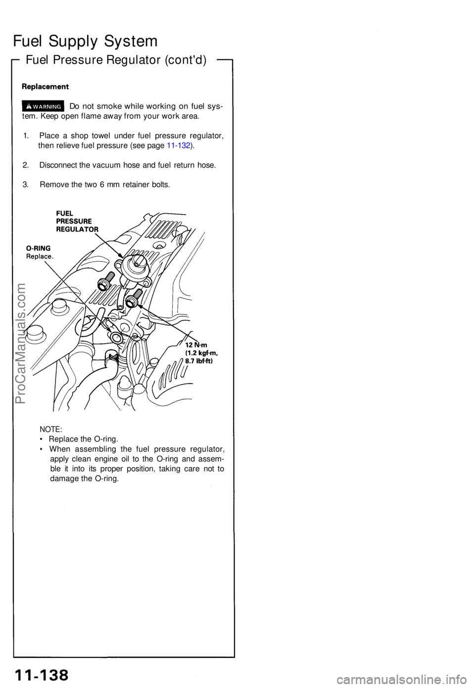
1. Plac e a sho p towe l unde r fue l pressur e regulator ,
the n reliev e fue l pressur e (se e pag e 11-132 ).
2 . Disconnec t th e vacuu m hos e an d fue l retur n hose .
3 . Remov e th e tw o 6 m m retaine r bolts .
NOTE :
• Replac e th e O-ring .
• Whe n assemblin g th e fue l pressur e regulator ,
appl y clea n engin e oi l t o th e O-rin g an d assem -
bl e i t int o it s prope r position , takin g car e no t t o
damag e th e O-ring .
Do no t smok e whil e workin g o n fue l sys -
tem. Kee p ope n flam e awa y fro m you r wor k area .
ProCarManuals.com
Page 258 of 1640
Fuel Suppl y Syste m
Fuel Filte r
Do no t smok e whil e workin g o n fue l sys -
tem . Kee p ope n flam e awa y fro m you r wor k area .
Th e fue l filte r shoul d b e replace d ever y 4 year s o r 60,00 0
mile s (96,00 0 km) , whicheve r come s first , o r wheneve r
th e fue l pressur e drop s belo w th e specifie d valu e [32 4 -
36 3 kP a (3. 3 - 3. 7 kgf/cm
2, 4 7 - 5 3 psi ) wit h th e fue l pres -
sur e regulato r vacuu m hos e disconnected ] afte r makin g
sur e tha t th e fue l pum p an d th e fue l pressur e regulato r
are OK .
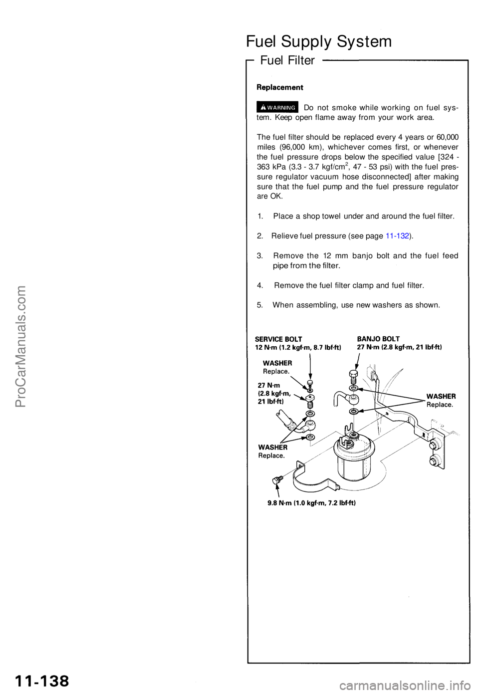
1. Plac e a sho p towe l unde r an d aroun d th e fue l filter .
2 . Reliev e fue l pressur e (se e pag e 11-132 ).
3 . Remov e th e 1 2 m m banj o bol t an d th e fue l fee d
pipe fro m th e filter .
4. Remov e th e fue l filte r clam p an d fue l filter .
5 . Whe n assembling , us e ne w washer s a s shown .
ProCarManuals.com
Page 259 of 1640
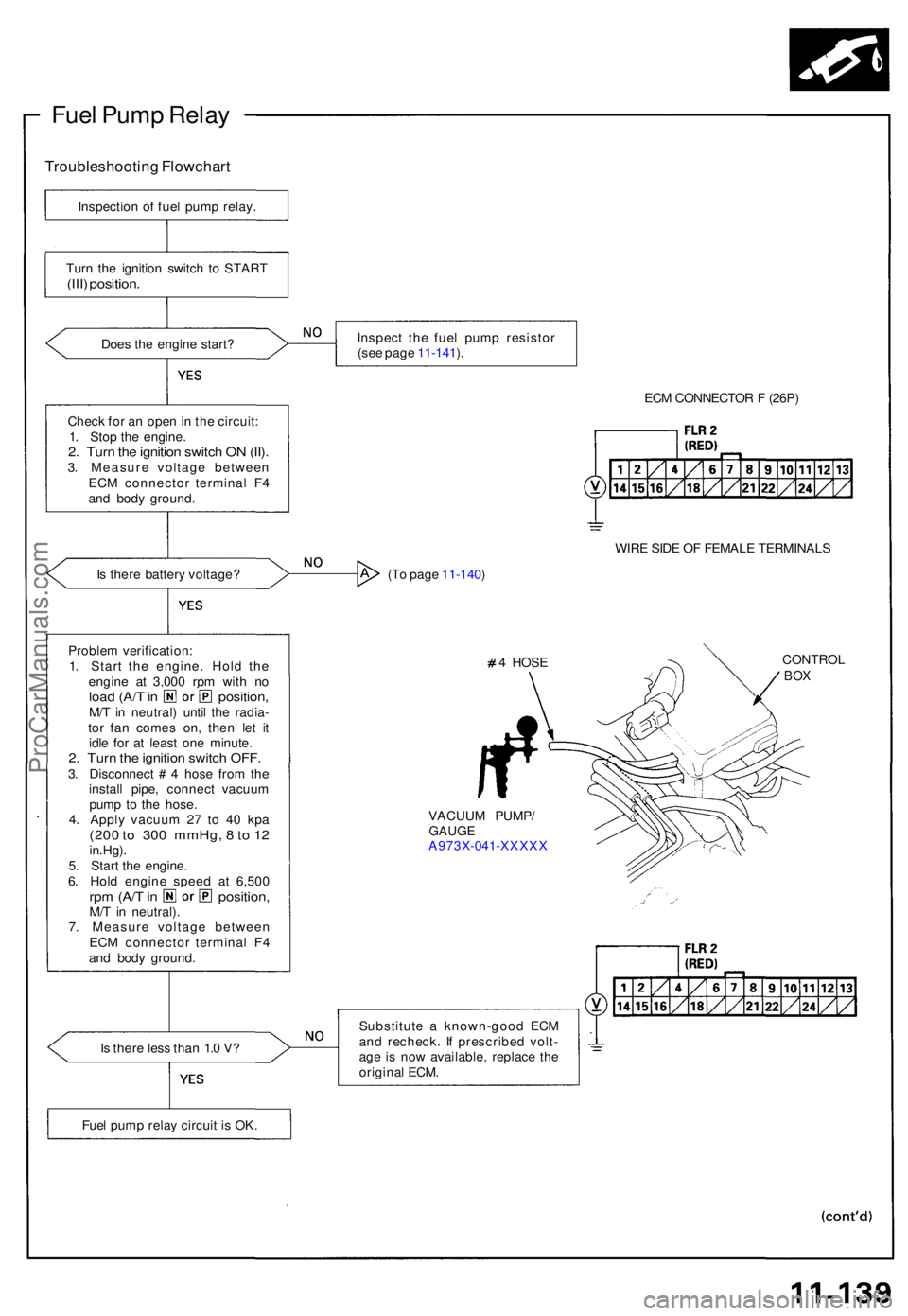
Fuel Pum p Rela y
Troubleshootin g Flowchar t
Inspection o f fue l pum p relay .
Tur n th e ignitio n switc h t o STAR T
(III) position .
Does th e engin e start ?
Chec k fo r a n ope n in th e circuit :
1 . Sto p th e engine .
2. Tur n th e ignitio n switc h O N (II) .3. Measur e voltag e betwee n
EC M connecto r termina l F 4
an d bod y ground .
I s ther e batter y voltage ?
Proble m verification :
1 . Star t th e engine . Hol d th e
engin e a t 3,00 0 rp m wit h n o
loa d (A/ T in position ,M/T in neutral ) unti l th e radia -
to r fa n come s on , the n le t i t
idl e fo r a t leas t on e minute .
2. Tur n th e ignitio n switc h OFF .3. Disconnec t # 4 hos e fro m th e
instal l pipe , connec t vacuu m
pum p t o th e hose .
4 . Appl y vacuu m 2 7 t o 4 0 kp a
(200 t o 300 mmHg , 8 to 1 2in.Hg) .
5 . Star t th e engine .
6 . Hol d engin e spee d a t 6,50 0
rpm (A/ T in position ,M/T in neutral) .
7 . Measur e voltag e betwee n
EC M connecto r termina l F 4
an d bod y ground .
I s ther e les s tha n 1. 0 V ? Inspec
t th e fue l pum p resisto r
(se e pag e 11-141 ).
ECM CONNECTO R F (26P )
WIR E SID E O F FEMAL E TERMINAL S
(T o pag e 11-140 )
4 HOS E
CONTRO LBOX
VACUU M PUMP /GAUGEA973X-04 1-XXXX X
Substitut e a known-goo d EC M
an d recheck . I f prescribe d volt -
ag e i s no w available , replac e th e
origina l ECM .
Fue l pum p rela y circui t i s OK .
ProCarManuals.com
Page 260 of 1640
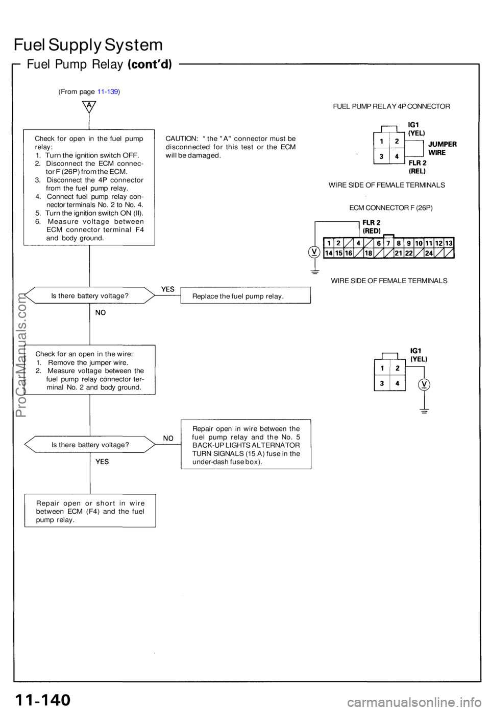
Fuel Suppl y Syste m
Fuel Pum p Rela y
(From pag e 11-139 )
FUEL PUM P RELA Y 4 P CONNECTO R
Chec k fo r ope n i n th e fue l pum p
relay:1. Tur n th e ignitio n switc h OFF .2. Disconnec t th e EC M connec -tor F (26P ) fro m th e ECM .3. Disconnec t th e 4 P connecto r
fro m th e fue l pum p relay .
4 . Connec t fue l pum p rela y con -
necto r terminal s No . 2 to No . 4 .
5. Tur n th e ignitio n switc h O N (II) .6. Measur e voltag e betwee n
EC M connecto r termina l F 4
an d bod y ground . CAUTION
: * th e "A " connecto r mus t b e
disconnecte d fo r thi s tes t o r th e EC M
will b e damaged .
WIRE SID E O F FEMAL E TERMINAL S
EC M CONNECTO R F (26P )
WIR E SID E O F FEMAL E TERMINAL S
I s ther e batter y voltage ?
Replace th e fue l pum p relay .
Chec k fo r a n ope n in th e wire :
1 . Remov e th e jumpe r wire .
2 . Measur e voltag e betwee n th e
fue l pum p rela y connecto r ter -
mina l No . 2 an d bod y ground .
I s ther e batter y voltage ? Repai
r ope n i n wir e betwee n th e
fue l pum p rela y an d th e No . 5
BACK-U P LIGHT S ALTERNATO R
TUR N SIGNAL S (1 5 A ) fus e in th e
under-das h fus e box) .
Repai r ope n o r shor t i n wir e
betwee n EC M (F4 ) an d th e fue l
pum p relay .
ProCarManuals.com