ACURA NSX 1991 Service Repair Manual
Manufacturer: ACURA, Model Year: 1991, Model line: NSX, Model: ACURA NSX 1991Pages: 1640, PDF Size: 60.48 MB
Page 241 of 1640
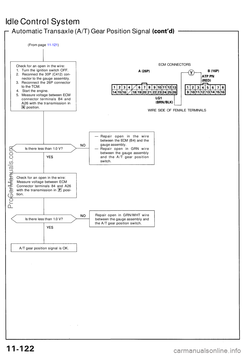
Idle Contro l Syste m
Automati c Transaxl e (A/T ) Gea r Positio n Signa l
(From pag e 11-121 )
Chec k fo r a n ope n in th e wire :
1 . Tur n th e ignitio n switc h OFF .
2. Reconnec t th e 30 P (C412 ) con -necto r t o th e gaug e assembly .
3 . Reconnec t th e 26 P connecto r
to th e TCM .4. Star t th e engine .
5 . Measur e voltag e betwee n EC M
connecto r terminal s B 4 an d
A26 wit h th e transmissio n i nposition . EC
M CONNECTOR S
WIR E SID E O F FEMAL E TERMINAL S
I s ther e les s tha n 1. 0 V ? —
Repai r ope n i n th e wir e
betwee n th e EC M (B4 ) an d th e
gaug e assembly .— Repai r ope n i n GR N wir e
betwee n th e gaug e assembl y
an d th e A/ T gea r positio n
switch .
Chec k fo r a n ope n in th e wire :
Measur e voltag e betwee n EC M
Connecto r terminal s 8 4 an d A2 6
with th e transmissio n i n posi -tion.
Is ther e les s tha n 1. 0 V ? Repai
r ope n i n GRN/WH T wir e
betwee n th e gaug e assembl y an d
th e A/ T gea r positio n switch .
A/ T gea r positio n signa l i s OK .
ProCarManuals.com
Page 242 of 1640
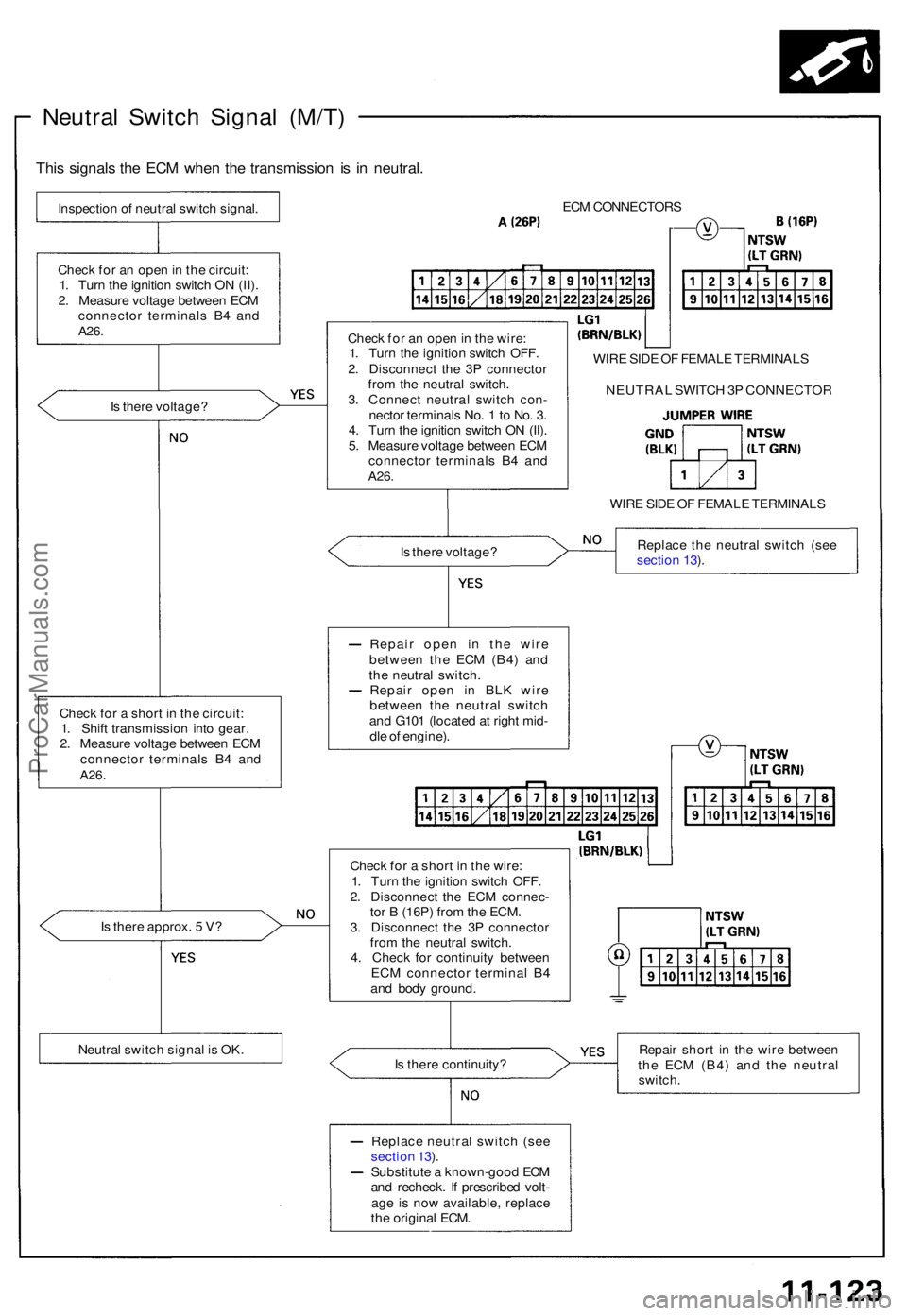
Neutral Switc h Signa l (M/T )
This signal s th e EC M whe n th e transmissio n i s i n neutral .
Inspectio n o f neutra l switc h signal .
Chec k fo r a n ope n in th e circuit :
1 . Tur n th e ignitio n switc h O N (II) .
2 . Measur e voltag e betwee n EC M
connecto r terminal s B 4 an d
A26 .
Is ther e voltage ?
Chec k fo r a shor t i n th e circuit :
1 . Shif t transmissio n int o gear .
2 . Measur e voltag e betwee n EC M
connecto r terminal s B 4 an d
A26 .
Is ther e approx . 5 V ?
Neutra l switc h signa l i s OK . EC
M CONNECTOR S
Chec k fo r a n ope n in th e wire :
1 . Tur n th e ignitio n switc h OFF .
2 . Disconnec t th e 3 P connecto r
fro m th e neutra l switch .
3 . Connec t neutra l switc h con -
necto r terminal s No . 1 to No . 3 .
4 . Tur n th e ignitio n switc h O N (II) .
5 . Measur e voltag e betwee n EC M
connecto r terminal s B 4 an d
A26 .
WIR E SID E O F FEMAL E TERMINAL S
WIR E SID E O F FEMAL E TERMINAL S
I s ther e voltage ? Replac
e th e neutra l switc h (se e
sectio n 13 ).
Repai r ope n i n th e wir e
betwee n th e EC M (B4 ) an d
th e neutra l switch .
Repai r ope n i n BL K wir e
betwee n th e neutra l switc h
an d G10 1 (locate d a t righ t mid -
dl e o f engine) .
Chec k fo r a shor t i n th e wire :
1 . Tur n th e ignitio n switc h OFF .
2 . Disconnec t th e EC M connec -
to r B (16P ) fro m th e ECM .
3 . Disconnec t th e 3 P connecto r
fro m th e neutra l switch .
4 . Chec k fo r continuit y betwee n
EC M connecto r termina l B 4
an d bod y ground .
I s ther e continuity ? Repai
r shor t i n th e wir e betwee n
th e EC M (B4 ) an d th e neutra l
switch .
Replac e neutra l switc h (se e
sectio n 13 ).
Substitut e a known-goo d EC M
an d recheck . I f prescribe d volt -
ag e i s no w available , replac e
th e origina l ECM . NEUTRA
L SWITC H 3 P CONNECTO R
ProCarManuals.com
Page 243 of 1640
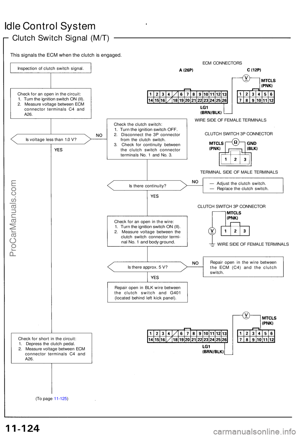
Idle Contro l Syste m
Clutch Switc h Signa l (M/T )
This signal s th e EC M whe n th e clutc h is engaged .
Inspection o f clutc h switc h signal .
Chec k fo r a n ope n in th e circuit :
1. Tur n th e ignitio n switc h O N (II) .2. Measur e voltag e betwee n EC M
connecto r terminal s C 4 an d
A26.
Is voltag e les s tha n 1. 0 V ?
Chec k fo r shor t i n th e circuit :
1 . Depres s th e clutc h pedal .
2 . Measur e voltag e betwee n EC M
connecto r terminal s C 4 an d
A26.
(To pag e 11-125 ) EC
M CONNECTOR S
Chec k th e clutc h switch :
1. Tur n th e ignitio n switc h OFF .2. Disconnec t th e 3 P connecto r
fro m th e clutc h switch .
3 . Chec k fo r continuit y betwee n
th e clutc h switc h connecto r
terminal s No . 1 an d No . 3 . WIR
E SID E O F FEMAL E TERMINAL S
CLUTC H SWITC H 3 P CONNECTO R
TERMINA L SID E O F MAL E TERMINAL S
I s ther e continuity ? —
Adjus t th e clutc h switch .
— Replac e th e clutc h switch .
CLUTC H SWITC H 3 P CONNECTO R
WIR E SID E O F FEMAL E TERMINAL S
I s ther e approx . 5 V ? Repai
r ope n i n th e wir e betwee n
th e EC M (C4 ) an d th e clutc h
switch .
Repai r ope n in BL K wir e betwee n
th e clutc h switc h an d G40 1
(locate d behin d lef t kic k panel) .
Chec
k fo r a n ope n in th e wire :
1. Tur n th e ignitio n switc h O N (II) .2. Measur e voltag e betwee n th e
clutc h switc h connecto r termi -
nal No . 1 an d bod y ground .
ProCarManuals.com
Page 244 of 1640
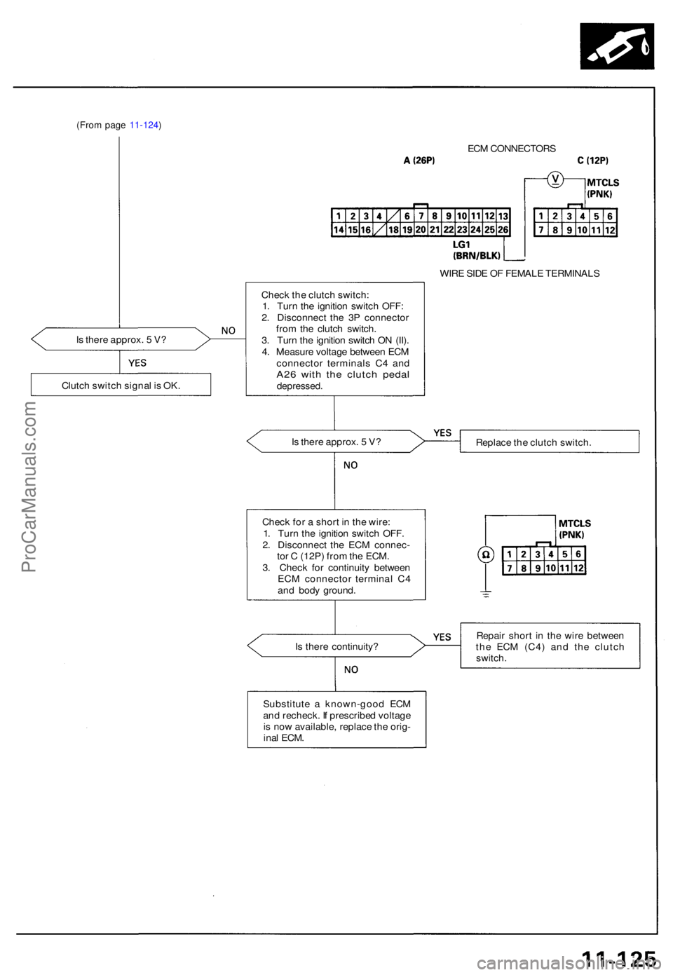
(From pag e 11-124 )
Is ther e approx . 5 V ? EC
M CONNECTOR S
Chec k th e clutc h switch :
1 . Tur n th e ignitio n switc h OFF :
2 . Disconnec t th e 3 P connecto r
fro m th e clutc h switch .
3 . Tur n th e ignitio n switc h O N (II) .
4 . Measur e voltag e betwee n EC M
connecto r terminal s C 4 an d
A26 wit h th e clutc h peda ldepressed .
Is ther e approx . 5 V ? WIR
E SID E O F FEMAL E TERMINAL S
Replac e th e clutc h switch .
Repai r shor t i n th e wir e betwee n
th e EC M (C4 ) an d th e clutc h
switch .
Clutc
h switc h signa l i s OK .
Check fo r a shor t i n th e wire :
1 . Tur n th e ignitio n switc h OFF .
2 . Disconnec t th e EC M connec -
to r C (12P ) fro m th e ECM .
3 . Chec k fo r continuit y betwee n
EC M connecto r termina l C 4
an d bod y ground .
I s ther e continuity ?
Substitut e a known-goo d EC M
an d recheck . I f prescribe d voltag e
i s no w available , replac e th e orig -
ina l ECM .
ProCarManuals.com
Page 245 of 1640
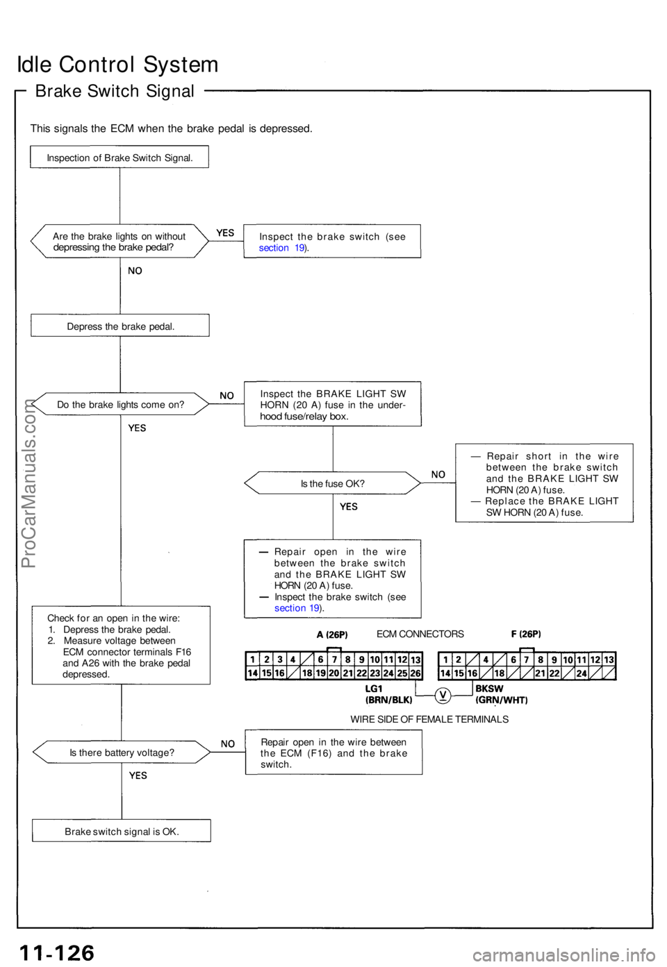
Idle Contro l Syste m
Brake Switc h Signa l
This signal s th e EC M whe n th e brak e peda l i s depressed .
Are th e brak e light s o n withou tdepressin g th e brak e pedal ?Inspec t th e brak e switc h (se e
sectio n 19 ).
Depres s th e brak e pedal .
D o th e brak e light s com e on ?
Is th e fus e OK ?
Chec k fo r a n ope n in th e wire :
1 . Depres s th e brak e pedal .
2 . Measur e voltag e betwee n
EC M connecto r terminal s F1 6
an d A2 6 wit h th e brak e peda l
depressed . —
Repai r shor t i n th e wir e
betwee n th e brak e switc h
an d th e BRAK E LIGH T S W
HOR N (2 0 A ) fuse .
— Replac e th e BRAK E LIGH T
S W HOR N (2 0 A ) fuse .
WIR E SID E O F FEMAL E TERMINAL S
I s ther e batter y voltage ? Repai
r ope n i n th e wir e betwee n
th e EC M (F16 ) an d th e brak e
switch .
Inspectio
n o f Brak e Switc h Signal .
Inspect th e BRAK E LIGH T S W
HORN (20 A ) fus e i n th e under -
hood fuse/rela y box .
Repai r ope n i n th e wir e
betwee n th e brak e switc h
an d th e BRAK E LIGH T S W
HOR N (2 0 A ) fuse .
Inspec t th e brak e switc h (se e
sectio n 19 ).
ECM CONNECTOR S
Brak e switc h signa l i s OK .
ProCarManuals.com
Page 246 of 1640
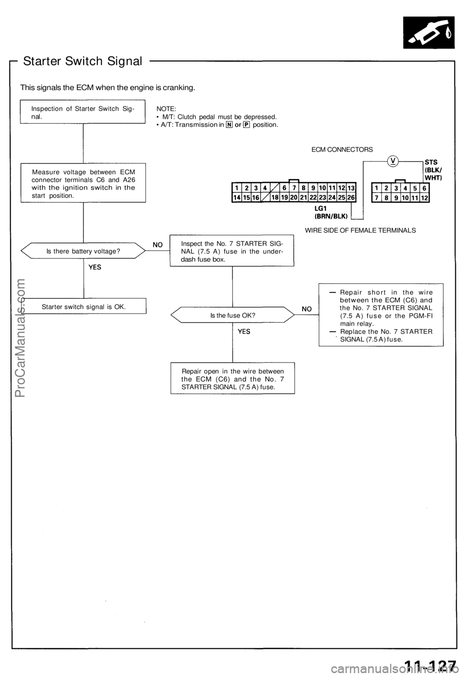
Starter Switch Signal
This signals the ECM when the engine is cranking.
Inspection of Starter Switch Sig-
nal.
NOTE:
• M/T: Clutch pedal must be depressed.
• A/T: Transmission in position.
ECM CONNECTORS
Measure voltage between ECM
connector terminals C6 and A26
with the ignition switch in the
start position.
WIRE SIDE OF FEMALE TERMINALS
Is there battery voltage?
Is the fuse OK?
Repair short in the wire
between the ECM (C6) and
the No. 7 STARTER SIGNAL
(7.5 A) fuse or the PGM-FI
main relay.
Replace the No. 7 STARTER
SIGNAL (7.5 A) fuse.
Starter switch signal is OK.
Repair open in the wire between
the ECM
(C6)
and the No. 7
STARTER SIGNAL (7.5 A) fuse.
Inspect the No. 7 STARTER SIG-
NAL (7.5 A) fuse in the under-
dash fuse box.ProCarManuals.com
Page 247 of 1640
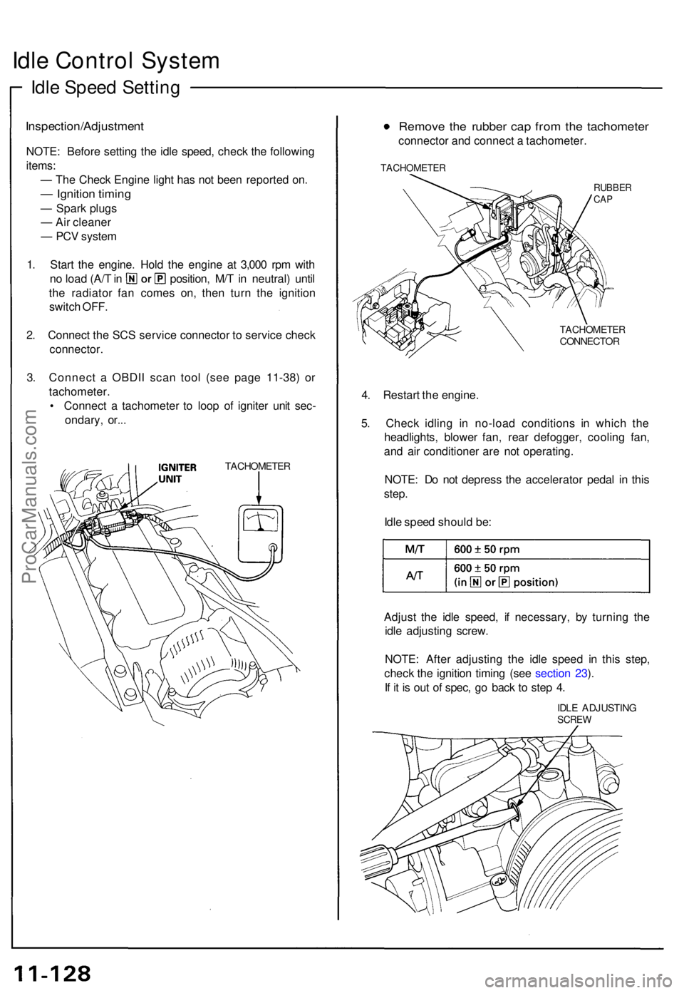
Idle Contro l Syste m
Idle Spee d Settin g
Inspection/Adjustmen t
NOTE: Befor e settin g th e idl e speed , chec k th e followin g
items :
— Th e Chec k Engin e ligh t ha s no t bee n reporte d on .
— Ignitio n timin g
— Spar k plug s
— Ai r cleane r
— PC V syste m
1 . Star t th e engine . Hol d th e engin e a t 3,00 0 rp m wit h
no loa d (A/ T in position , M/ T in neutral ) unti l
th e radiato r fa n come s on , the n tur n th e ignitio n
switc h OFF .
2 . Connec t th e SC S servic e connecto r t o servic e chec k
connector .
3. Connec t a OBDI I sca n too l (se e pag e 11-38 ) o r
tachometer .
• Connec t a tachomete r t o loo p o f ignite r uni t sec -
ondary , or.. .
TACHOMETE R
Remove th e rubbe r ca p fro m th e tachomete r
connector an d connec t a tachometer .
TACHOMETE R
RUBBERCAP
TACHOMETE RCONNECTOR
4. Restar t th e engine .
5 . Chec k idlin g i n no-loa d condition s i n whic h th e
headlights , blowe r fan , rea r defogger , coolin g fan ,
an d ai r conditione r ar e no t operating .
NOTE : D o no t depres s th e accelerato r peda l i n thi s
step .
Idl e spee d shoul d be :
Adjus t th e idl e speed , i f necessary , b y turnin g th e
idl e adjustin g screw .
NOTE : Afte r adjustin g th e idl e spee d i n thi s step ,
chec k th e ignitio n timin g (se e sectio n 23 ).
I f i t i s ou t o f spec , g o bac k t o ste p 4 .
IDL E ADJUSTIN GSCREW
ProCarManuals.com
Page 248 of 1640
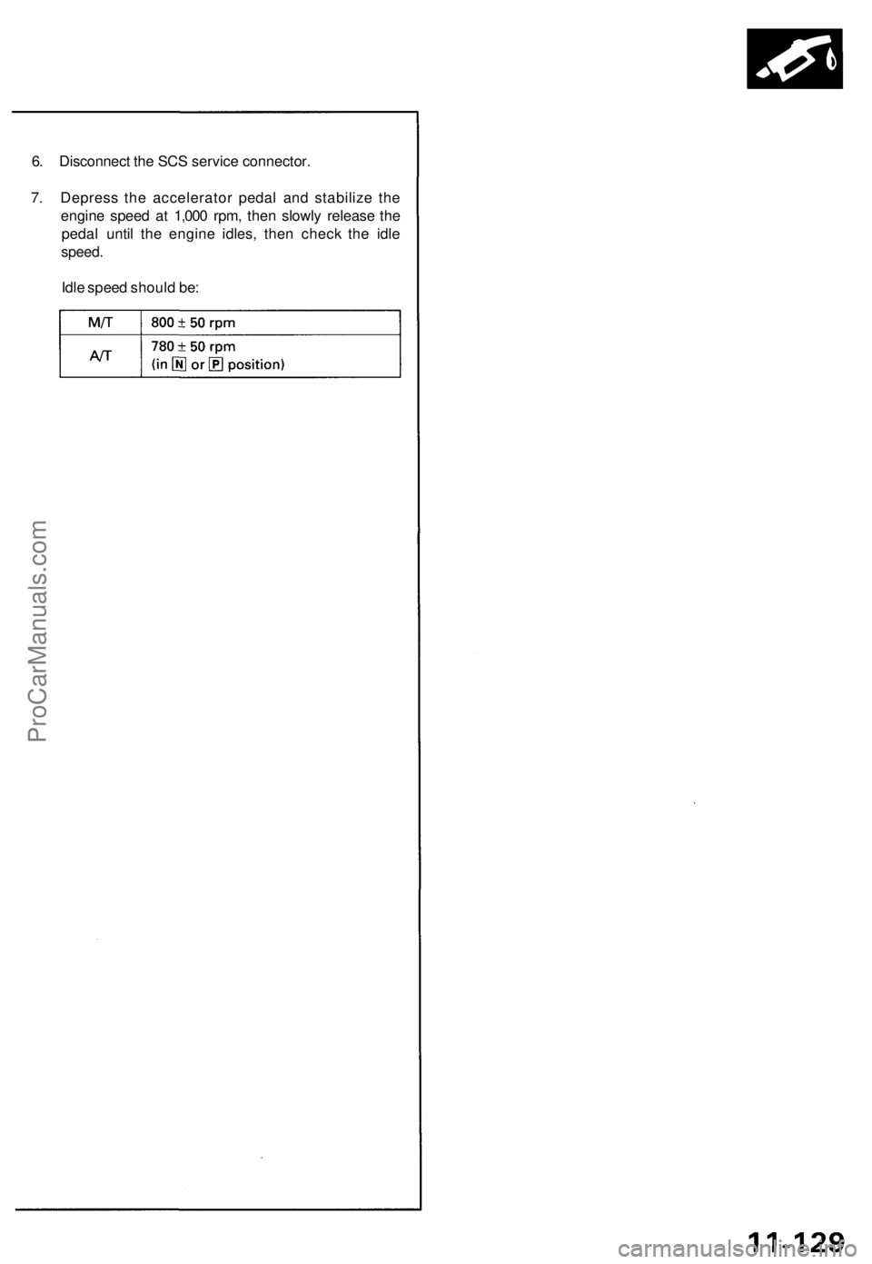
6. Disconnect the SCS service connector.
7. Depress the accelerator pedal and stabilize the
engine speed at 1,000 rpm, then slowly release the
pedal until the engine idles, then check the idle
speed.
Idle speed should be:ProCarManuals.com
Page 249 of 1640
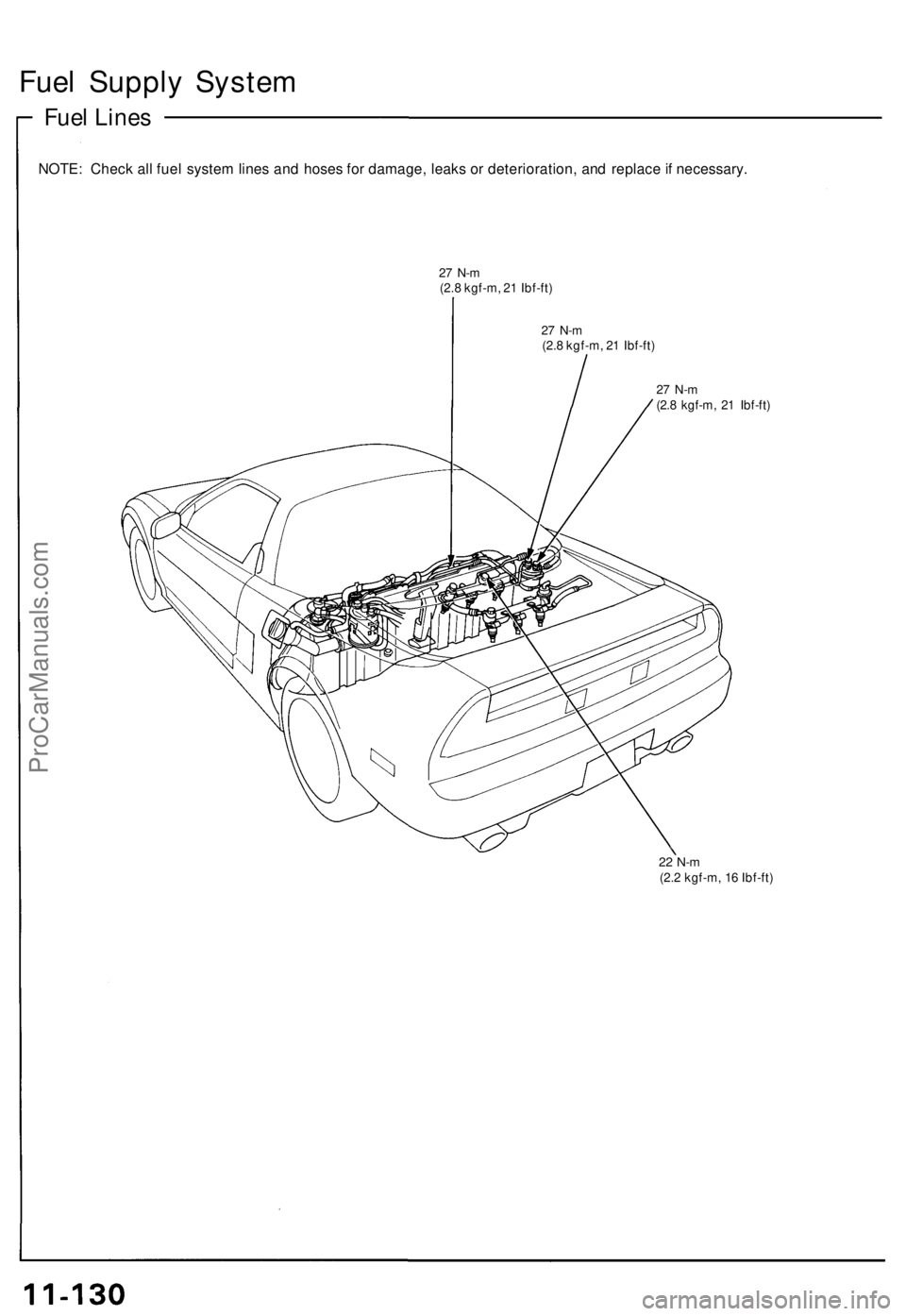
Fuel Supply System
Fuel Lines
NOTE: Check all fuel system lines and hoses for damage, leaks or deterioration, and replace if necessary.
27 N-m
(2.8 kgf-m, 21 Ibf-ft)
27 N-m
(2.8 kgf-m, 21 Ibf-ft)
27 N-m
(2.8 kgf-m, 21 Ibf-ft)
22 N-m
(2.2 kgf-m, 16 Ibf-ft)ProCarManuals.com
Page 250 of 1640
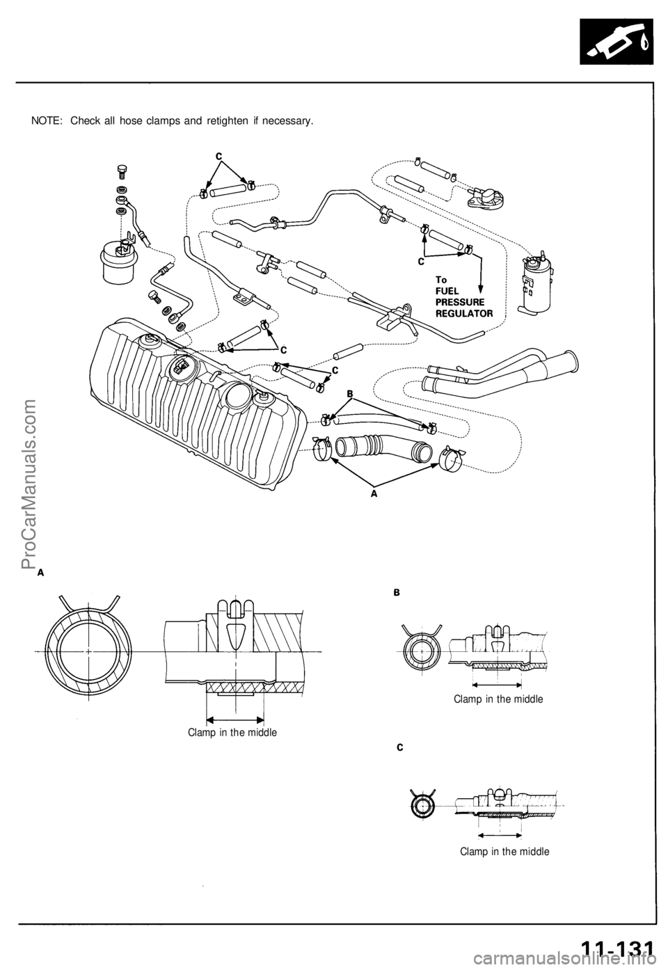
NOTE: Check all hose clamps and retighten if necessary.
Clamp in the middle
Clamp in the middle
Clamp in the middleProCarManuals.com