ACURA NSX 1991 Service Repair Manual
Manufacturer: ACURA, Model Year: 1991, Model line: NSX, Model: ACURA NSX 1991Pages: 1640, PDF Size: 60.48 MB
Page 331 of 1640
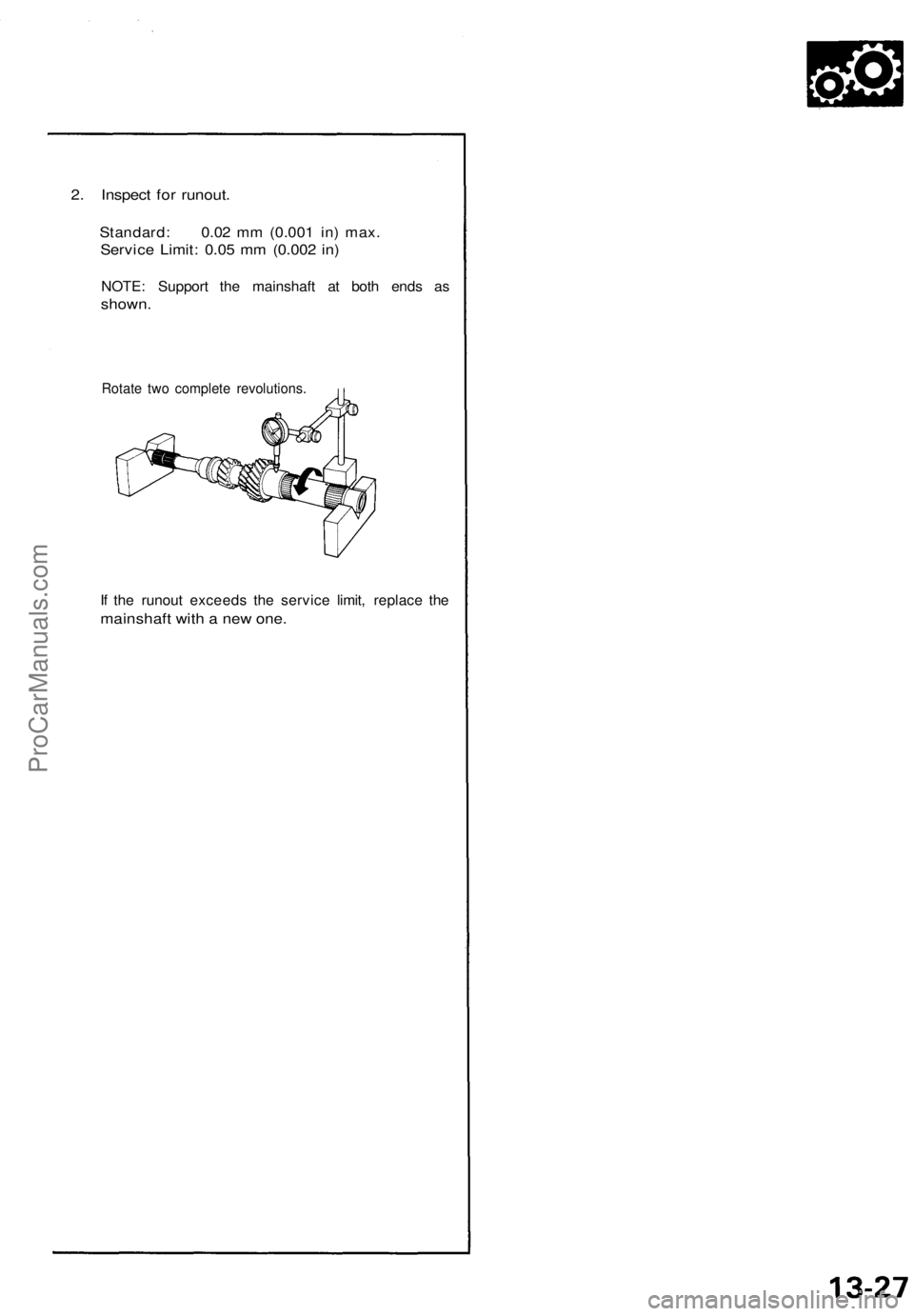
2. Inspect for runout.
Standard: 0.02 mm (0.001 in) max.
Service Limit: 0.05 mm (0.002 in)
NOTE: Support the mainshaft at both ends as
shown.
Rotate two complete revolutions.
If the runout exceeds the service limit, replace the
mainshaft with a new one.ProCarManuals.com
Page 332 of 1640
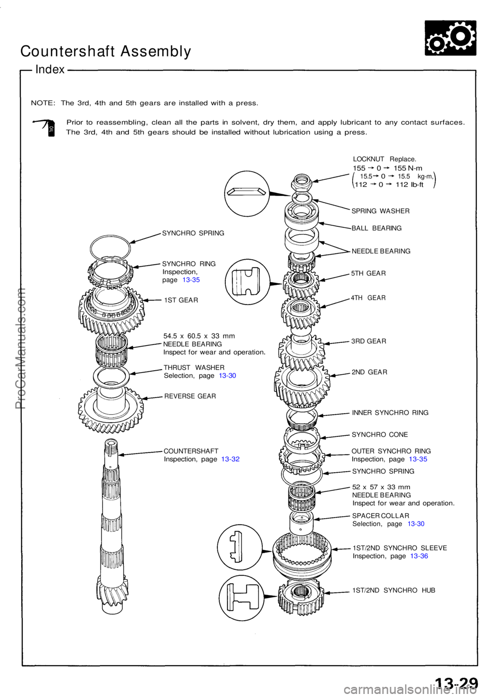
Countershaft Assembl y
Index
NOTE : Th e 3rd , 4t h an d 5t h gear s ar e installe d wit h a press .
Prior t o reassembling , clea n al l th e part s i n solvent , dr y them , an d appl y lubrican t t o an y contac t surfaces .
The 3rd , 4t h an d 5t h gear s shoul d b e installe d withou t lubricatio n usin g a press .
SYNCHR O SPRIN G
SYNCHR O RIN G
Inspection ,page 13-3 5
1S T GEA R
54.5 x 60. 5 x 3 3 m mNEEDL E BEARIN GInspect fo r wea r an d operatio n
THRUST WASHE RSelection, pag e 13-3 0
REVERS E GEA R
COUNTERSHAF TInspection, pag e 13-3 2
SPRIN G WASHE R
BAL L BEARIN G
NEEDL E BEARIN G
5T H GEA R
4TH GEA R
3RD GEA R
2N D GEA R
INNE R SYNCHR O RIN G
SYNCHR O CON E
OUTE R SYNCHR O RIN G
Inspection , pag e 13-3 5
SYNCHR O SPRIN G
52 x 5 7 x 33 m mNEEDL E BEARIN GInspect fo r wea r an d operation .
SPACER COLLA R
Selection , pag e 13-3 0
1ST/2N D SYNCHR O SLEEV E
Inspection , pag e 13-3 6
1ST/2N D SYNCHR O HU B
LOCKNU
T Replace .
155 0 15 5 N- m15. 5 0 15. 5 kg-m ,112 0 11 2 Ib-f t
ProCarManuals.com
Page 333 of 1640
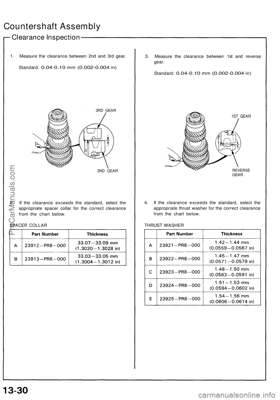
Countershaft Assembly
Clearance Inspectio n
1. Measur e th e clearanc e betwee n 2n d an d 3r d gear .
Standard :
0.04-0.10 mm (0.002-0.00 4 in)
3R D GEA R
2ND GEA R
2. I f th e clearanc e exceed s th e standard , selec t th e
appropriat e space r colla r fo r th e correc t clearanc e
fro m th e char t below .
SPACE R COLLA R
3. Measur e th e clearanc e betwee n 1s t an d revers e
gear .
Standard :
0.04-0.10 mm (0.002-0.00 4 in)
1S T GEA R
REVERS EGEAR
4. I f th e clearanc e exceed s th e standard , selec t th e
appropriat e thrus t washe r fo r th e correc t clearanc e
fro m th e char t below .
THRUS T WASHE R
ProCarManuals.com
Page 334 of 1640
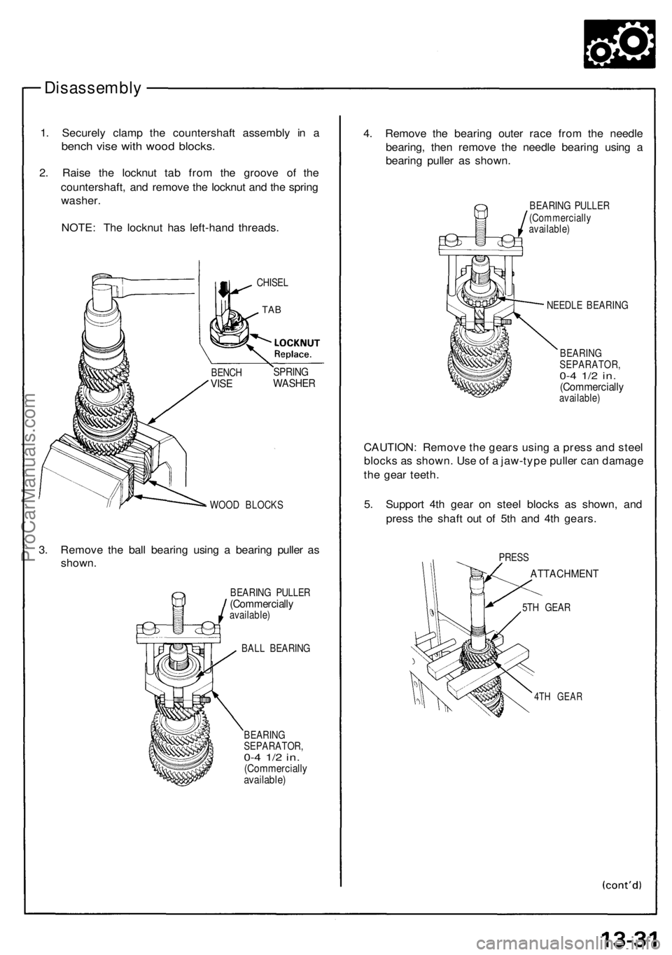
Disassembly
1. Securely clamp the countershaft assembly in a
bench vise with wood blocks.
2. Raise the locknut tab from the groove of the
countershaft, and remove the locknut and the spring
washer.
NOTE: The locknut has left-hand threads.
WOOD BLOCKS
3. Remove the ball bearing using a bearing puller as
shown.
BEARING PULLER
(Commercially
available)
BALL BEARING
BEARING
SEPARATOR,
0-4 1/2 in.
(Commercially
available)
4. Remove the bearing outer race from the needle
bearing, then remove the needle bearing using a
bearing puller as shown.
BEARING PULLER
(Commercially
available)
NEEDLE BEARING
BEARING
SEPARATOR,
0-4 1/2 in.
(Commercially
available)
CAUTION: Remove the gears using a press and steel
blocks as shown. Use of a jaw-type puller can damage
the gear teeth.
5. Support 4th gear on steel blocks as shown, and
press the shaft out of 5th and 4th gears.
5TH GEAR
4TH GEAR
PRESS
ATTACHMENT
BENCH
VISE
SPRING
WASHER
TAB
CHISELProCarManuals.com
Page 335 of 1640
Countershaft Assembl y
Disassembl y
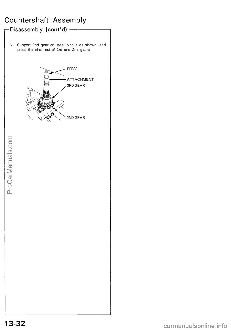
6. Suppor t 2n d gea r o n stee l block s a s shown , an d
pres s th e shaf t ou t o f 3r d an d 2n d gears .
PRESS
ATTACHMEN T
3RD GEA R
2N D GEA R
ProCarManuals.com
Page 336 of 1640
Countershaft Assembl y
Inspection
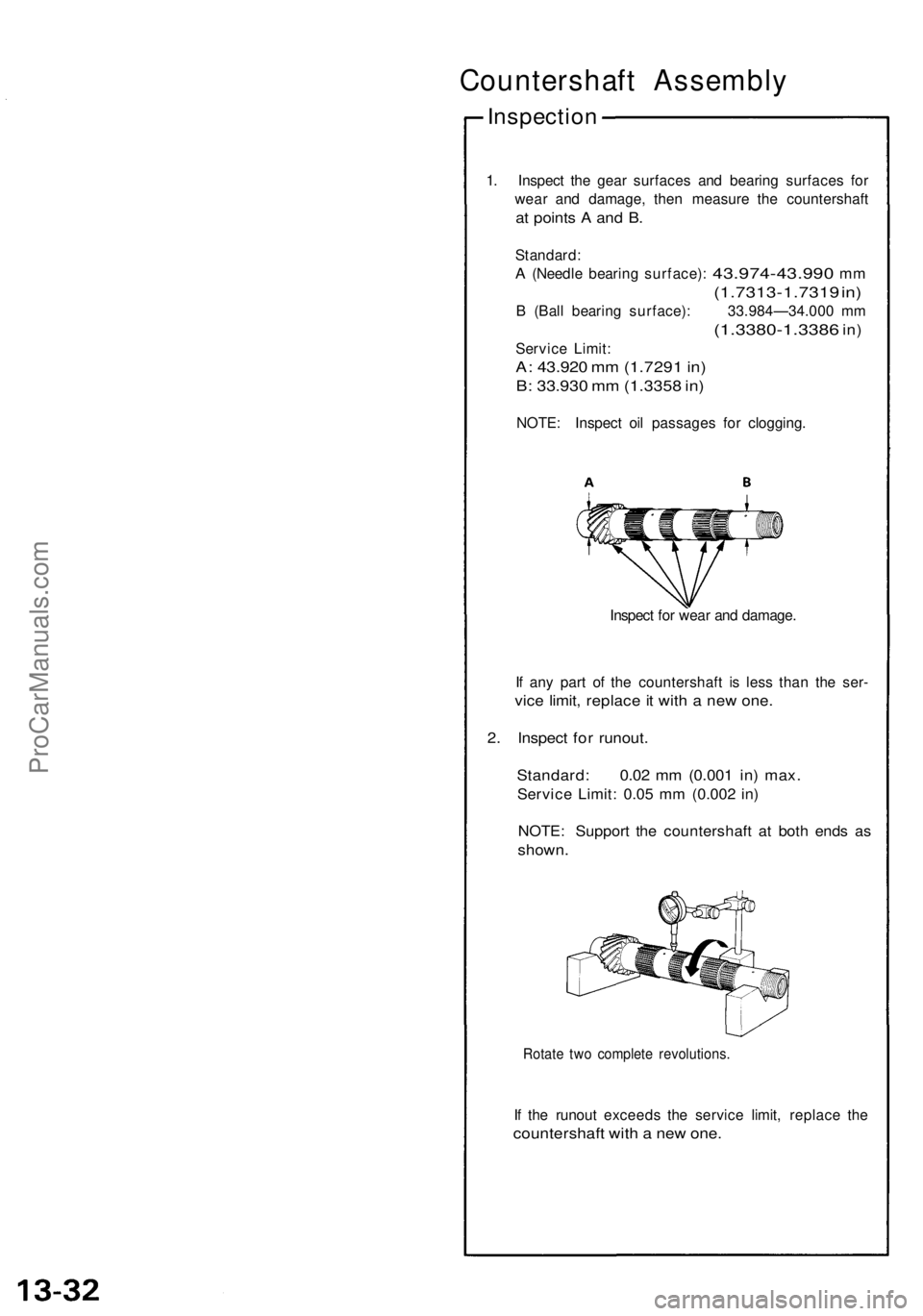
1. Inspec t th e gea r surface s an d bearin g surface s fo r
wea r an d damage , the n measur e th e countershaf t
at point s A an d B .
Standard :
A (Needle bearin g surface) : 43.974-43.99 0 mm
(1.7313-1.731 9 in )
B (Bal l bearin g surface) : 33.984—34.00 0 m m
(1.3380-1.338 6 in)
Servic e Limit :
A: 43.92 0 m m (1.729 1 in )
B: 33.93 0 m m (1.335 8 in )
NOTE : Inspec t oi l passage s fo r clogging .
Inspec t fo r wea r an d damage .
I f an y par t o f th e countershaf t i s les s tha n th e ser -
vice limit , replac e it wit h a ne w one .
2. Inspec t fo r runout .
Standard : 0.0 2 m m (0.00 1 in ) max .
Servic e Limit : 0.0 5 m m (0.00 2 in )
NOTE : Suppor t th e countershaf t a t bot h end s a s
shown .
Rotate tw o complet e revolutions .
If th e runou t exceed s th e servic e limit , replac e th e
countershaf t wit h a ne w one .
ProCarManuals.com
Page 337 of 1640
Reassembly
CAUTION:
• Prio r t o reassembling , clea n al l th e part s i n solvent ,
dr y them , an d appl y lubrican t t o an y contac t parts .
• Pres s th e 3rd , 4t h an d 5t h gears on th e countershaf t
withou t lubrication .
• Whe n installin g th e 3rd , 4t h an d 5t h gears , suppor t
th e shaf t o n stee l blocks , an d instal l th e gear s usin g
a press .
• Instal l th e 3rd , 4t h an d 5t h gear s wit h a maximu m
pressur e o f 1,00 0 kg , the n pres s al l thre e gears with
a pressur e o f 2,60 0 kg .
NOTE : T o reassemble , se e pag e 13-29 .
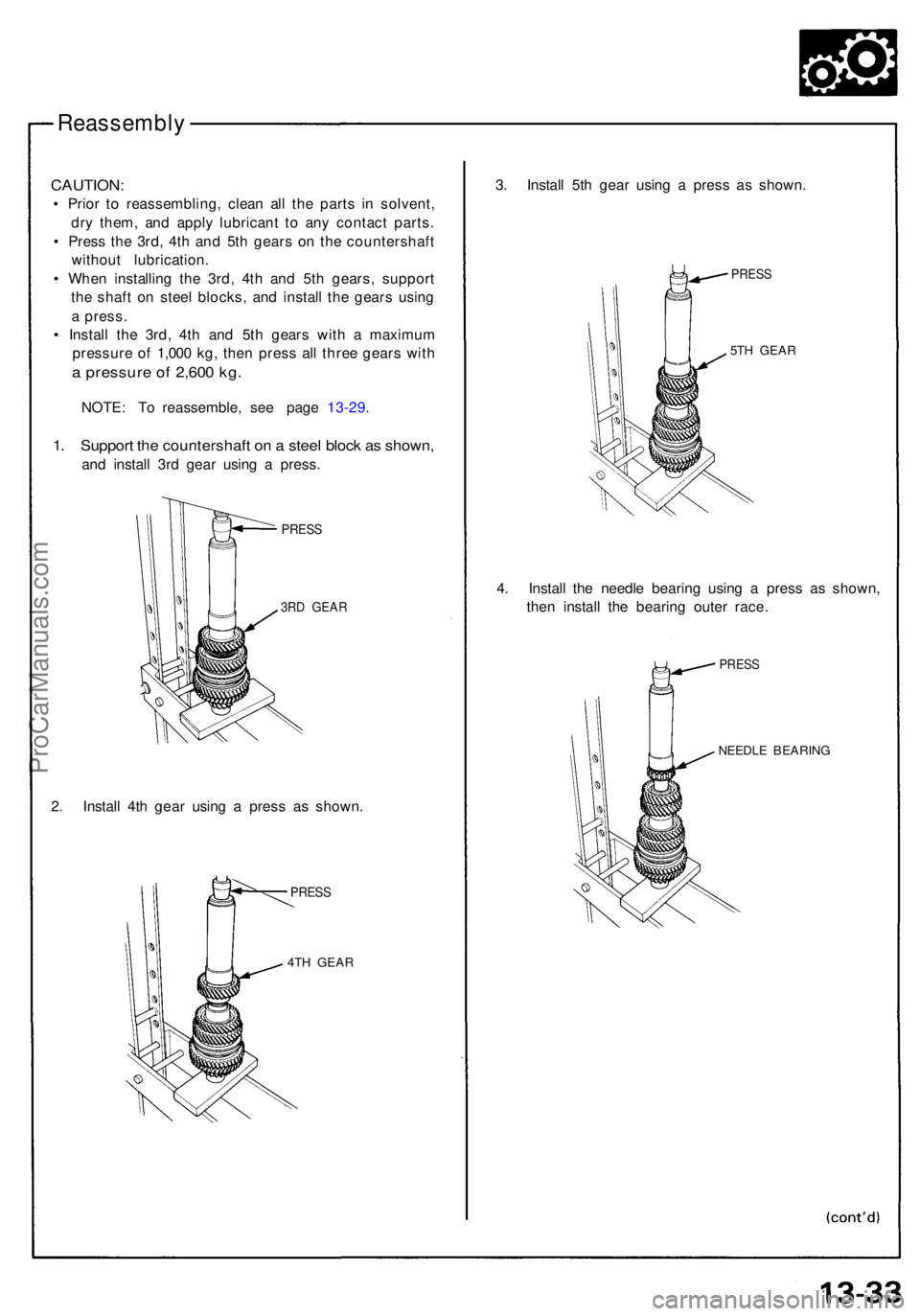
1. Suppor t th e countershaf t o n a stee l bloc k a s shown ,
and instal l 3r d gea r usin g a press .
PRESS
3RD GEA R
2. Instal l 4t h gea r usin g a pres s a s shown .
PRESS
4TH GEA R
3. Instal l 5t h gea r usin g a pres s a s shown .
PRESS
5TH GEA R
4. Instal l th e needl e bearin g usin g a pres s a s shown ,
the n instal l th e bearin g oute r race .
PRES S
NEEDL E BEARIN G
ProCarManuals.com
Page 338 of 1640
Countershaft Assembly
Reassembly
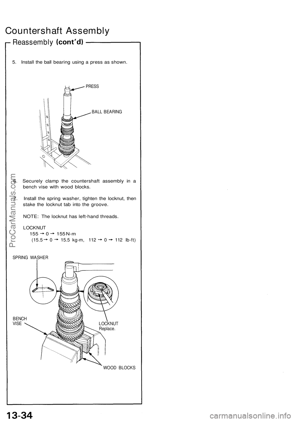
5. Install the ball bearing using a press as shown.
PRESS
BALL BEARING
6. Securely clamp the countershaft assembly in a
bench vise with wood blocks.
7. Install the spring washer, tighten the locknut, then
stake the locknut tab into the groove.
NOTE: The locknut has left-hand threads.
LOCKNUT
155 0 155 N-m
(15.5 0 15.5 kg-m, 112 0 112 Ib-ft)
SPRING WASHER
BENCH
VISE
WOOD BLOCKS
LOCKNUT
Replace.ProCarManuals.com
Page 339 of 1640
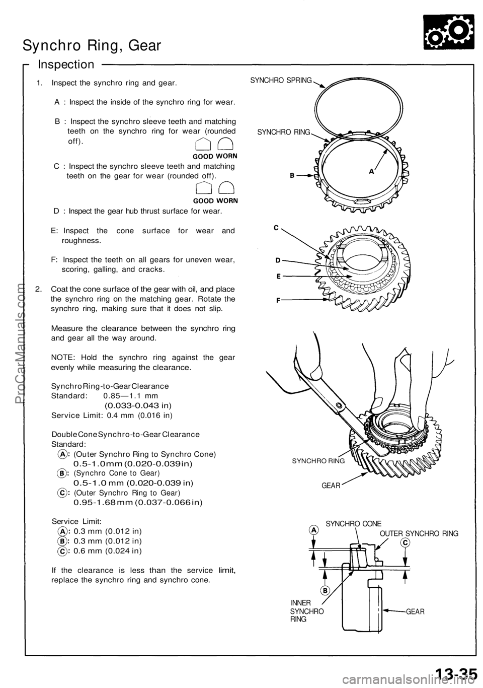
Synchro Ring , Gea r
Inspectio n
1. Inspec t th e synchr o rin g an d gear .
A : Inspec t th e insid e of the synchr o rin g fo r wear .
B : Inspec t th e synchr o sleev e teet h an d matchin g
teet h o n th e synchr o rin g fo r wea r (rounde d
off).
C : Inspec t th e synchr o sleev e teet h an d matchin g
teet h o n th e gea r fo r wea r (rounde d off) .
D : Inspec t th e gea r hu b thrus t surfac e fo r wear .
E : Inspec t th e con e surfac e fo r wea r an d
roughness .
F : Inspec t th e teet h o n al l gear s fo r uneve n wear ,
scoring , galling , an d cracks .
2. Coa t th e con e surfac e o f th e gea r wit h oil , an d plac e
the synchr o rin g o n th e matchin g gear . Rotat e th e
synchr o ring , makin g sur e tha t i t doe s no t slip .
Measur e th e clearanc e betwee n th e synchr o rin g
and gea r al l th e wa y around .
NOTE : Hol d th e synchr o rin g agains t th e gea r
evenly whil e measurin g th e clearance .
Synchro Ring-to-Gea r Clearanc e
Standard : 0.85—1. 1 m m
(0.033-0.04 3 in)
Servic e Limit : 0. 4 m m (0.01 6 in )
Doubl e Con e Synchro-to-Gea r Clearanc e
Standard :
(Oute r Synchr o Rin g to Synchr o Cone )
0.5-1.0 m m (0.020-0.03 9 in )
(Synchr o Con e t o Gear )
0.5-1.0 mm (0.020-0.03 9 in)
(Oute r Synchr o Rin g t o Gear )
0.95-1.6 8 m m (0.037-0.06 6 in )
Servic e Limit :
0.3 m m (0.01 2 in )
0.3 m m (0.01 2 in )
0.6 m m (0.02 4 in )
If th e clearanc e is les s than the servic e limit,
replac e th e synchr o rin g an d synchr o cone .
SYNCHR O SPRIN G
SYNCHR O RIN G
SYNCHR O RIN G
GEA R
SYNCHR O CON E
INNERSYNCHR ORING
OUTE R SYNCHR O RIN G
GEA R
ProCarManuals.com
Page 340 of 1640
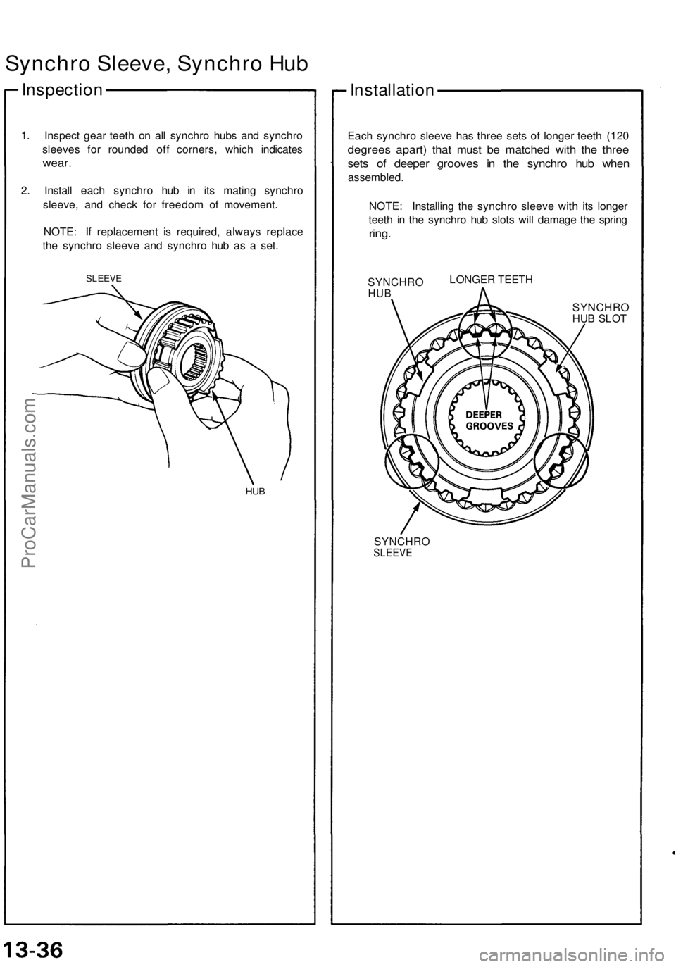
Synchro Sleeve , Synchr o Hu b
Inspectio n
1. Inspec t gea r teet h o n al l synchr o hub s an d synchr o
sleeve s fo r rounde d of f corners , whic h indicate s
wear.
2. Instal l eac h synchr o hu b i n it s matin g synchr o
sleeve , an d chec k fo r freedo m o f movement .
NOTE : I f replacemen t i s required , alway s replac e
th e synchr o sleev e an d synchr o hu b a s a set .
SLEEV E
HUB
Installatio n
Each synchr o sleev e ha s thre e set s o f longe r teet h (12 0
degree s apart ) tha t mus t b e matche d wit h th e thre e
sets o f deepe r groove s i n th e synchr o hu b whe n
assembled .
NOTE : Installin g th e synchr o sleev e wit h it s longe r
teet h i n th e synchr o hu b slot s wil l damag e th e sprin g
ring.
SYNCHR OHUB
LONGER TEETH
SYNCHR OHUB SLOT
SYNCHROSLEEVE
ProCarManuals.com