ACURA NSX 1991 Service Repair Manual
Manufacturer: ACURA, Model Year: 1991, Model line: NSX, Model: ACURA NSX 1991Pages: 1640, PDF Size: 60.48 MB
Page 371 of 1640
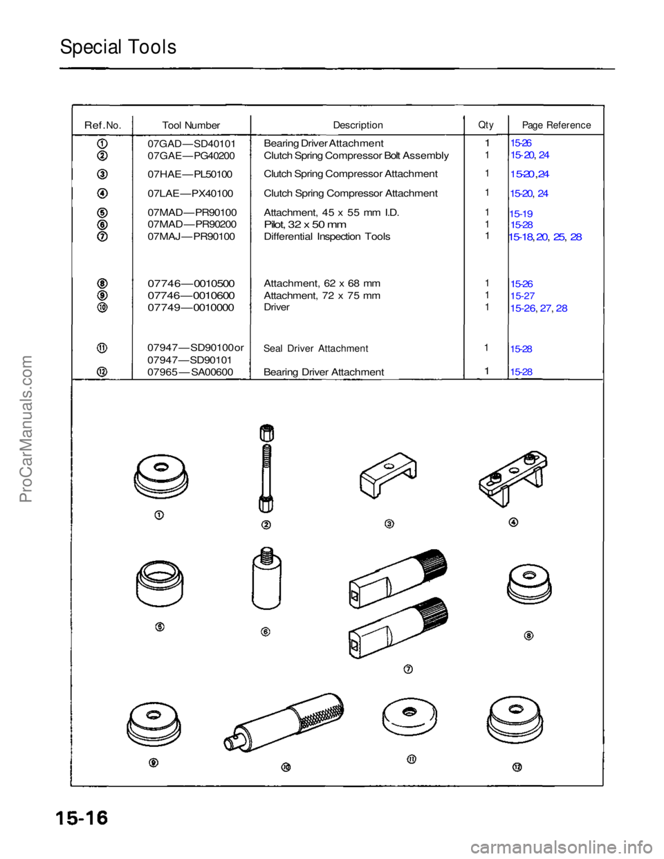
Special Tools
Ref.
No.
Tool Number
07GAD — SD40101
07GAE — PG40200
07HAE — PL50100
07LAE — PX40100
07MAD — PR90100
07MAD — PR90200
07MAJ — PR90100
07746 — 0010500
07746 — 0010600
07749 — 0010000
07947 — SD90100 or
07947 — SD90101
07965 — SA00600
Description
Bearing Driver Attachment
Clutch Spring Compressor Bolt Assembly
Clutch Spring Compressor Attachment
Clutch Spring Compressor Attachment
Attachment, 45 x 55 mm I.D.
Pilot, 32 x 50 mm
Differential Inspection Tools
Attachment, 62 x 68 mm
Attachment, 72 x 75 mm
Driver
Seal Driver Attachment
Bearing Driver Attachment
Qty
1
1
1
1
1
1
1
1
1
1
1
1
Page Reference
15-26
15- 20, 24
1 5-20 , 24
15-20, 24
15-19
15-28
15-18, 20, 25, 28
15-26
15-27
15-26, 27, 28
15-28
15-28
ProCarManuals.com
Page 372 of 1640
Differential
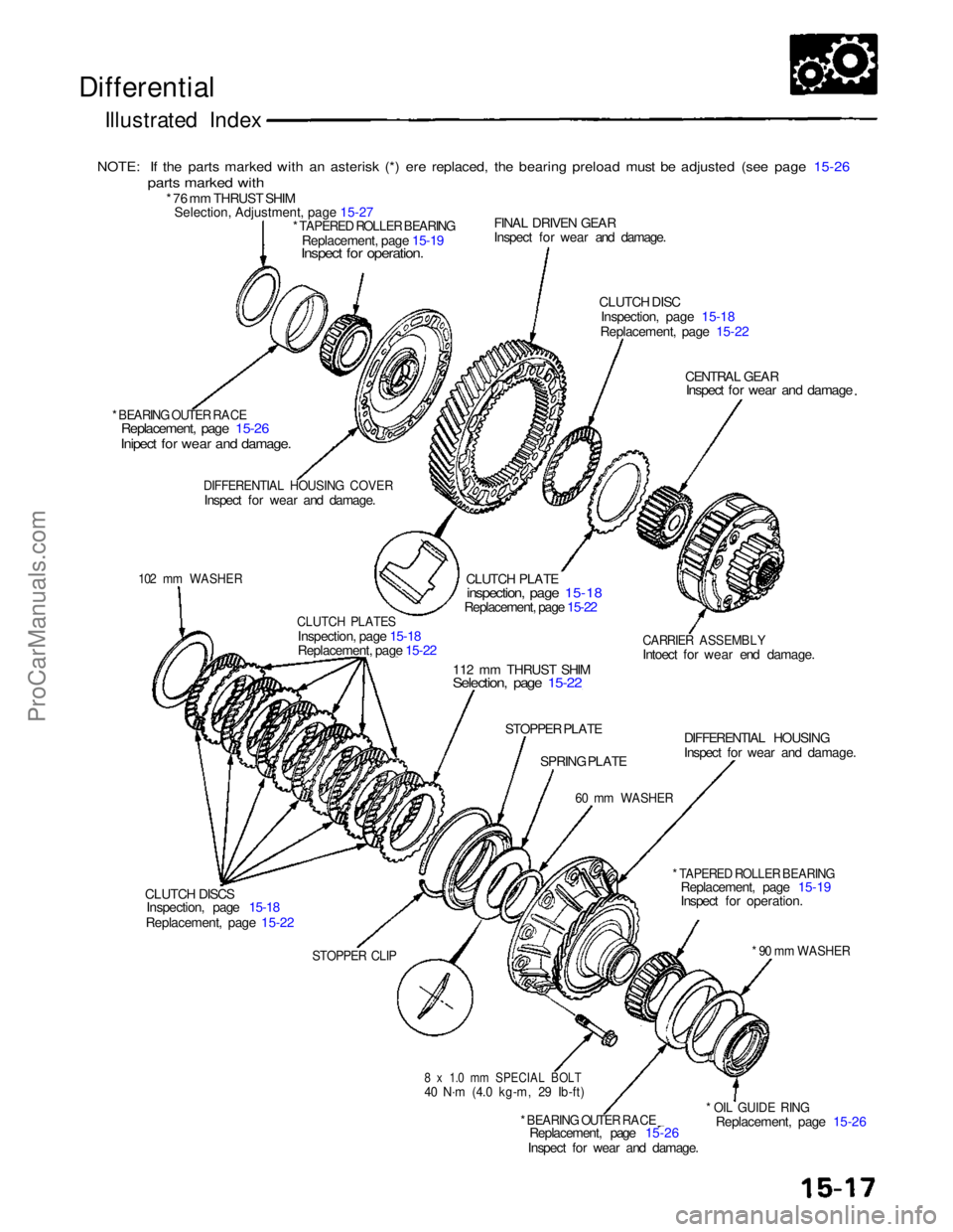
Illustrated Index
NOTE: If the parts marked with an asterisk (*) ere replaced, the bearing preload must be adjusted (see page 15-26
parts marked with
* 76 mm THRUST SHIM
Selection, Adjustment, page 15-27
* TAPERED ROLLER BEARING
Replacement, page 15-19
Inspect for operation.
FINAL DRIVEN GEAR
Inspect for wear and damage.
CLUTCH DISCInspection, page 15-18
Replacement, page 15-22
CENTRAL GEAR
Inspect for wear and damage
* BEARING OUTER RACE
Replacement, page 15-26
Inipect for wear and damage.
DIFFERENTIAL HOUSING COVER
Inspect for wear and damage.
CLUTCH PLATE
inspection, page 15-18
Replacement, page 15-22
CARRIER ASSEMBLY
Intoect for wear end damage.
102 mm WASHER
CLUTCH PLATES
Inspection, page 15-18
Replacement, page 15-22
112 mm THRUST SHIM
Selection, page 15-22
STOPPER PLATE DIFFERENTIAL HOUSING
Inspect for wear and damage.
SPRING PLATE
60 mm WASHER
* TAPERED ROLLER BEARING
Replacement, page 15-19
Inspect for operation.
* 90 mm WASHER
* OIL GUIDE RING
Replacement, page 15-26
STOPPER CLIP
8 x 1.0 mm SPECIAL BOLT
40 N·m (4.0 kg-m, 29 Ib-ft)
* BEARING OUTER RACE
Replacement, page 15-26
Inspect for wear and damage.
CLUTCH DISCS
Inspection, page 15-18
Replacement, page 15-22ProCarManuals.com
Page 373 of 1640
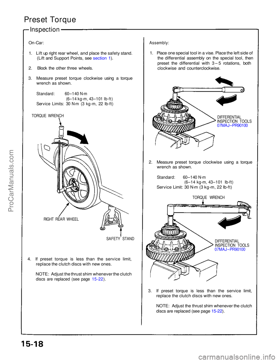
Preset Torque
Inspection
On-Car:
1. Lift up right rear wheel,
and place the safety stand.
(Lift and Support Points, see section 1).
2. Block the other three wheels.
3. Measure preset torque clockwise using a torque wrench as shown.
Standard:
60–140 N·m
(6–14 kg-m, 43–101 Ib-ft)
Service Limits: 30 N·m (3 kg-m, 22 Ib-ft)
TORQUE WRENCH
RIGHT REAR WHEEL SAFETY STAND
4. If preset torque is less than the service limit, replace the clutch discs with new ones.
NOTE: Adjust the thrust shim whenever the clutch
discs are replaced (see page 15-22).
Assembly:
1. Place one special tool in a vise. Place the left side of the differential assembly on the special tool, then
preset the differential with 3 – 5 rotations, both
clockwise and counterclockwise.
DIFFERENTIAL
INSPECTION TOOLS
07MAJ– PR90100
2. Measure preset torque clockwise using a torque wrench as shown.
Standard: 60–140 N·m
(6–14 kg-m, 43–101 Ib-ft)
Service Limit: 30 N·m (3 kg-m, 22 Ib-ft)
TORQUE WRENCH
DIFFERENTIAL
INSPECTION TOOLS
07MAJ – PR90100
3. If preset torque is less than the service limit, replace the clutch discs with new ones.
NOTE: Adjust the thrust shim whenever the clutch
discs are replaced (see page 15-22).
ProCarManuals.com
Page 374 of 1640
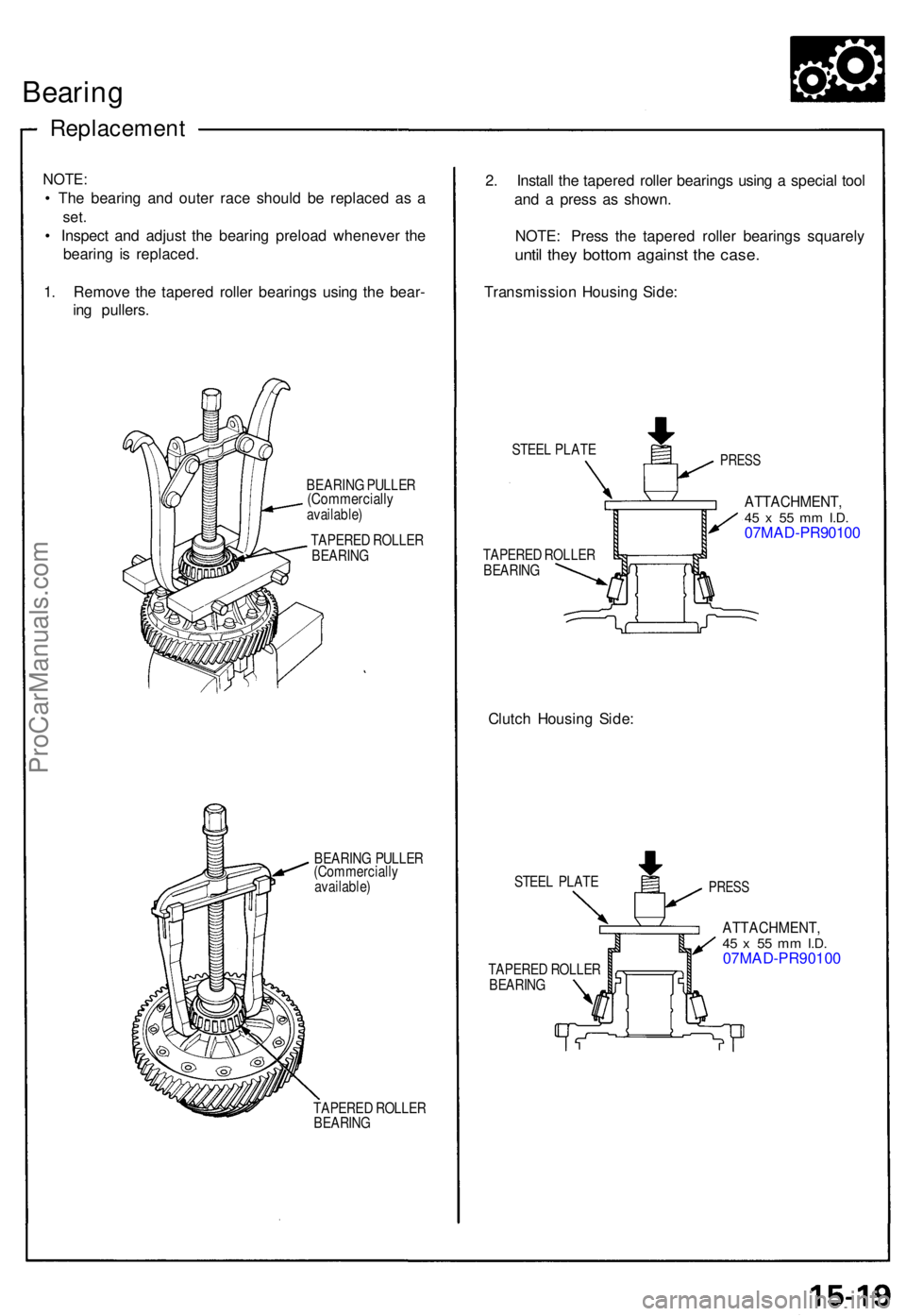
Bearing
Replacemen t
NOTE:
• Th e bearin g an d oute r rac e shoul d b e replace d a s a
set .
• Inspec t an d adjus t th e bearin g preloa d wheneve r th e
bearin g i s replaced .
1 . Remov e th e tapere d rolle r bearing s usin g th e bear -
in g pullers .
BEARIN G PULLE R(Commerciall yavailable)
TAPERE D ROLLE R
BEARIN G
BEARIN G PULLE R
(Commerciall y
available )
TAPERE D ROLLE R
BEARIN G
2. Instal l th e tapere d rolle r bearing s usin g a specia l too l
an d a pres s a s shown .
NOTE : Pres s th e tapere d rolle r bearing s squarel y
until the y botto m agains t th e case .
Transmissio n Housin g Side :
STEE L PLAT EPRESS
TAPERE D ROLLE R
BEARIN G
Clutch Housin g Side :
STEE L PLAT E
TAPERE D ROLLE R
BEARIN G
ATTACHMENT ,45 x 5 5 m m I.D .07MA D-PR9010 0
PRESS
ATTACHMENT ,45 x 5 5 m m I.D .07MAD-PR90100
ProCarManuals.com
Page 375 of 1640
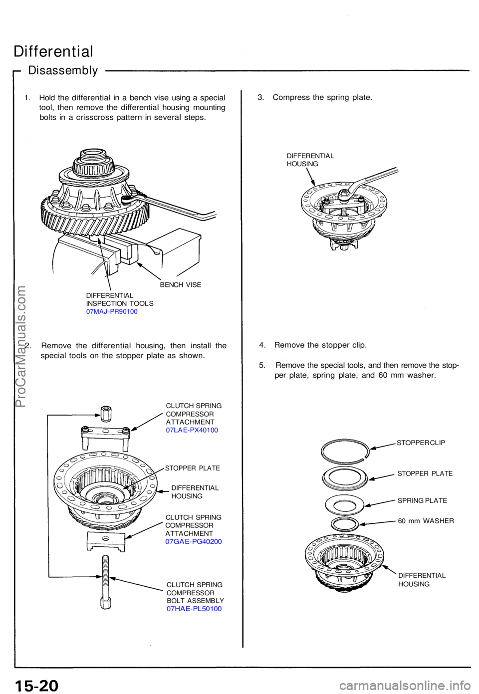
Differential
Disassembl y
1. Hol d th e differentia l i n a benc h vis e usin g a specia l
tool , the n remov e th e differentia l housin g mountin g
bolt s i n a crisscros s patter n i n severa l steps .
BENCH VIS E
DIFFERENTIA LINSPECTION TOOL S07MAJ-PR90100
2. Remov e th e differentia l housing , the n instal l th e
specia l tool s o n th e stoppe r plat e a s shown .
CLUTCH SPRIN GCOMPRESSO RATTACHMENT
07LA E-PX4010 0
STOPPE R PLAT E
DIFFERENTIA LHOUSING
CLUTC H SPRIN G
COMPRESSO RATTACHMENT07GAE-PG4020 0
CLUTCH SPRIN GCOMPRESSO RBOLT ASSEMBL Y07HAE-PL5010 0
3. Compres s th e sprin g plate .
DIFFERENTIA LHOUSING
4. Remov e th e stoppe r clip .
5 . Remov e th e specia l tools , an d the n remov e th e stop -
pe r plate , sprin g plate , an d 6 0 m m washer .
STOPPE R CLI P
STOPPE R PLAT E
SPRING PLAT E
6 0 m m WASHE R
DIFFERENTIA LHOUSING
ProCarManuals.com
Page 376 of 1640
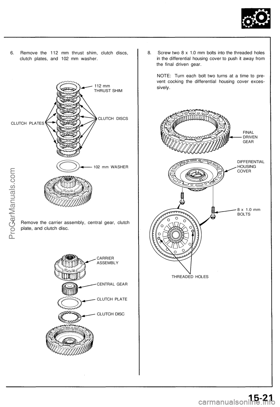
6. Remove the 112 mm thrust shim, clutch discs,
clutch plates, and 102 mm washer.
112 mm
THRUST SHIM
CLUTCH PLATES
CLUTCH DISCS
102 mm WASHER
7. Remove the carrier assembly, central gear, clutch
plate, and clutch disc.
CARRIER
ASSEMBLY
CENTRAL GEAR
CLUTCH PLATE
CLUTCH DISC
8. Screw two 8 x 1.0 mm bolts into the threaded holes
in the differential housing cover to push it away from
the final driven gear.
NOTE: Turn each bolt two turns at a time to pre-
vent cocking the differential housing cover exces-
sively.
THREADED HOLES
FINAL
DRIVEN
GEAR
DIFFERENTIAL
HOUSING
COVER
8 x 1.0 mm
BOLTSProCarManuals.com
Page 377 of 1640
\
I
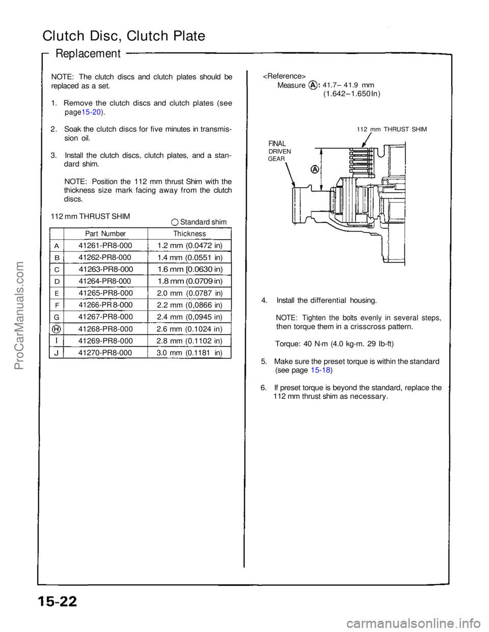
Clutch Disc, Clutch Plate
Replacement
NOTE: The clutch discs and clutch plates should be
replaced as a set.
1. Remove the clutch discs and clutch plates (see
page15-20).
2. Soak the clutch discs for five minutes in transmis-
sion oil.
3. Install the clutch discs, clutch plates, and a stan- dard shim.
NOTE: Position the 112 mm thrust Shim with the
thickness size mark facing away from the clutch
discs.
112 mm THRUST SHIM
Standard shim
A
B
C
D
E
F
G
J
Part Number
41261-PR8-000
41262-PR8-000
41263-PR8-000
41264-PR8-000
41265-PR8-000
41266-PR
8-000
41267-PR8-000
41268-PR8-000
41269-PR8-000
41270-PR8-000
Thickness
1.2 mm (0.0472 in)
1.4 mm (0.0551 in)
1.6 mm [0.0630 in)
1.8 mm (0.0709 in)
2.0 mm (0.0787 in)
2.2 mm (0,0866 in)
2.4 mm (0,0945 in)
2.6 mm (0.1024 in)
2.8 mm (0.1102 in)
3.0 mm (0.1181 in)
Measure
41.7– 41.9
mm
(1.642 – 1.650 In)
112 mm THRUST SHIM
FINAL
DRIVEN
GEAR
4. Install the differential housing.
NOTE: Tighten the bolts evenly in several steps,
then torque them in a crisscross pattern.
Torque: 40 N·m (4.0 kg-m. 29 Ib-ft)
5. Make sure the preset torque is within the standard (see page 15-18)
6. If preset torque is beyond the standard, replace the 112 mm thrust shim as necessary.ProCarManuals.com
Page 378 of 1640
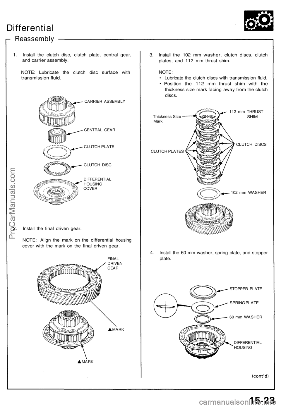
Differential
Reassembl y
1. Instal l th e clutc h disc , clutc h plate , centra l gear ,
an d carrie r assembly .
NOTE : Lubricat e th e clutc h dis c surfac e wit h
transmissio n fluid .
CARRIE R ASSEMBL Y
CENTRAL GEA R
CLUTC H PLAT E
CLUTC H DIS C
DIFFERENTIA LHOUSINGCOVER
2. Instal l th e fina l drive n gear .
NOTE : Alig n th e mar k o n th e differentia l housin g
cove r wit h th e mar k o n th e fina l drive n gear .
FINALDRIVE NGEAR
MAR K
MAR K
3. Instal l th e 10 2 m m washer , clutc h discs , clutc h
plates , an d 11 2 m m thrus t shim .
NOTE :
• Lubricat e th e clutc h disc s wit h transmissio n fluid .
• Positio n th e 11 2 m m thrus t shi m wit h th e
thicknes s siz e mar k facin g awa y fro m th e clutc h
discs .
Thicknes s Siz eMar k
CLUTC H PLATE S 11
2 m m THRUS T
SHIM
CLUTC H DISC S
10 2 m m WASHE R
4. Instal l th e 6 0 m m washer , sprin g plate , an d stoppe r
plate .
STOPPE R PLAT E
SPRING PLAT E
6 0 m m WASHE R
DIFFERENTIA LHOUSING
ProCarManuals.com
Page 379 of 1640
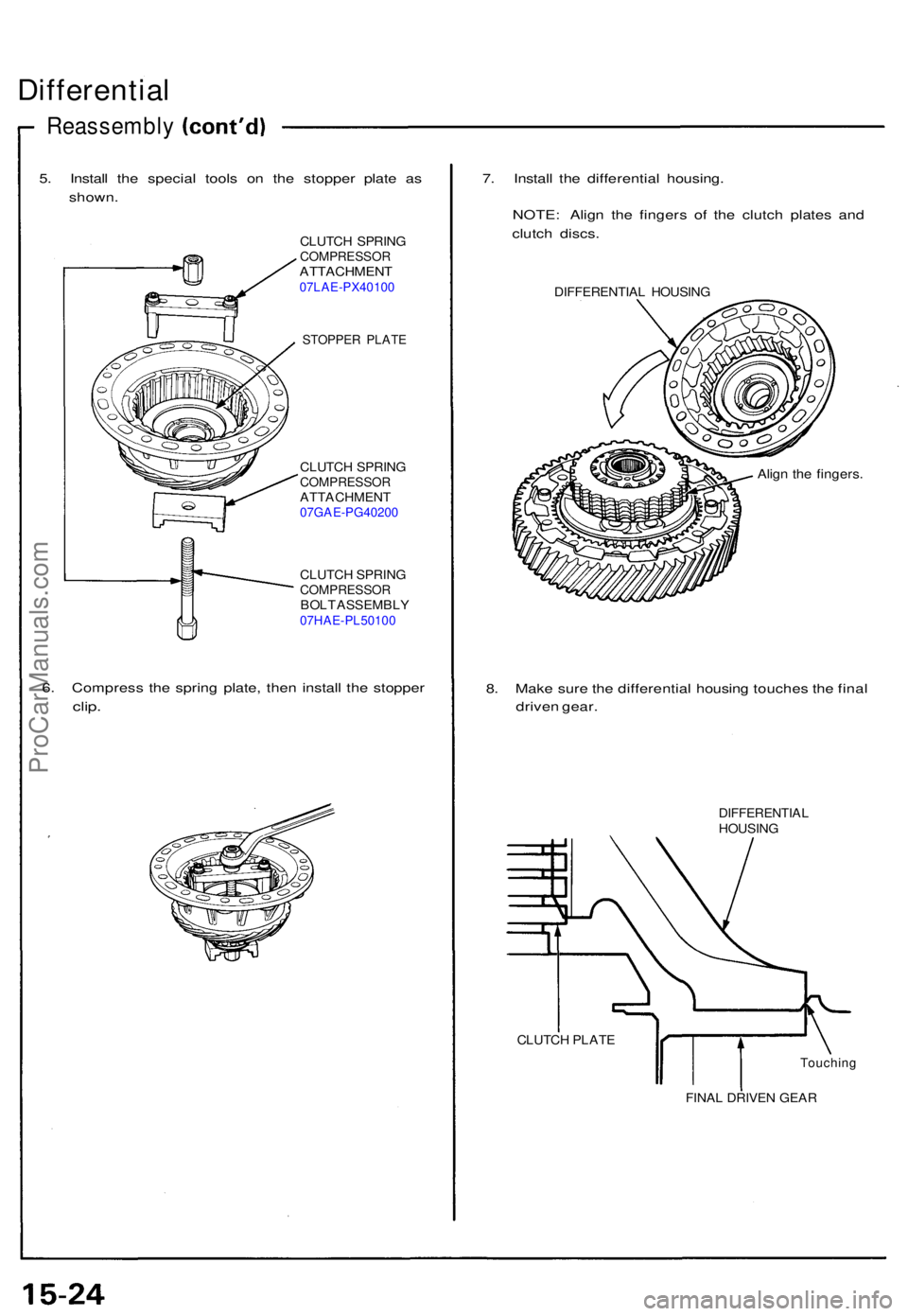
Differential
Reassembl y
5. Instal l th e specia l tool s o n th e stoppe r plat e a s
shown .
CLUTC H SPRIN GCOMPRESSO RATTACHMENT07LAE-PX40100
STOPPER PLAT E
CLUTC H SPRIN GCOMPRESSO RATTACHMENT07GAE-PG40200
CLUTCH SPRIN GCOMPRESSO RBOLT ASSEMBL Y07HAE-PL50100
6. Compres s th e sprin g plate , the n instal l th e stoppe r
clip.
7. Instal l th e differentia l housing .
NOTE : Alig n th e finger s o f th e clutc h plate s an d
clutc h discs .
DIFFERENTIA L HOUSIN G
Align th e fingers .
8. Mak e sur e th e differentia l housin g touche s th e fina l
drive n gear .
DIFFERENTIA LHOUSING
CLUTC H PLAT E
Touchin g
FINAL DRIVE N GEA R
ProCarManuals.com
Page 380 of 1640
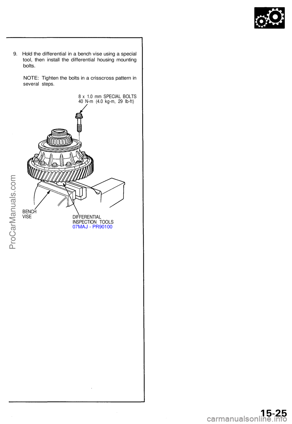
9. Hol d th e differentia l i n a benc h vis e usin g a specia l
tool , the n instal l th e differentia l housin g mountin g
bolts.
NOTE : Tighte n th e bolt s in a crisscros s patter n in
severa l steps .
8 x 1. 0 m m SPECIA L BOLT S
4 0 N- m (4. 0 kg-m , 2 9 Ib-ft )
BENC H
VIS E
DIFFERENTIAL
INSPECTIO N TOOL S
07MAJ - PR90100
ProCarManuals.com