ACURA NSX 1991 Service Repair Manual
Manufacturer: ACURA, Model Year: 1991, Model line: NSX, Model: ACURA NSX 1991Pages: 1640, PDF Size: 60.48 MB
Page 921 of 1640
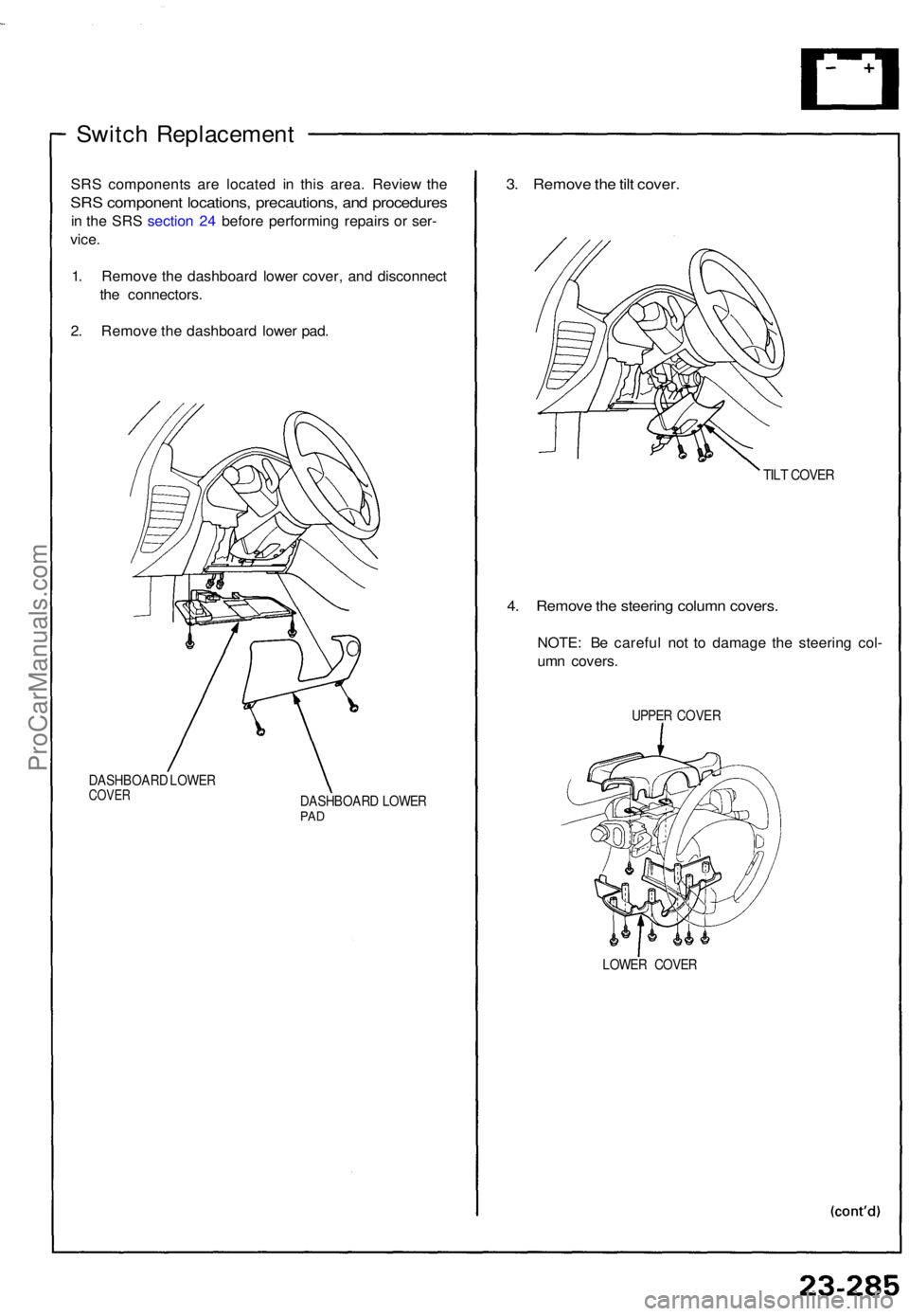
Switch Replacemen t
SRS component s ar e locate d i n thi s area . Revie w th e
SR S componen t locations , precautions , an d procedure s
in th e SR S sectio n 24 befor e performin g repair s o r ser -
vice .
1 . Remov e th e dashboar d lowe r cover , an d disconnec t
th e connectors .
2 . Remov e th e dashboar d lowe r pad .
DASHBOAR D LOWE RCOVERDASHBOAR D LOWE RPAD
3. Remov e th e til t cover .
TILT COVE R
4. Remov e th e steerin g colum n covers .
NOTE: B e carefu l no t t o damag e th e steerin g col -
um n covers .
UPPER COVE R
LOWE R COVE R
ProCarManuals.com
Page 922 of 1640
Rear Window Defogger
Switch Replacement (cont'd)
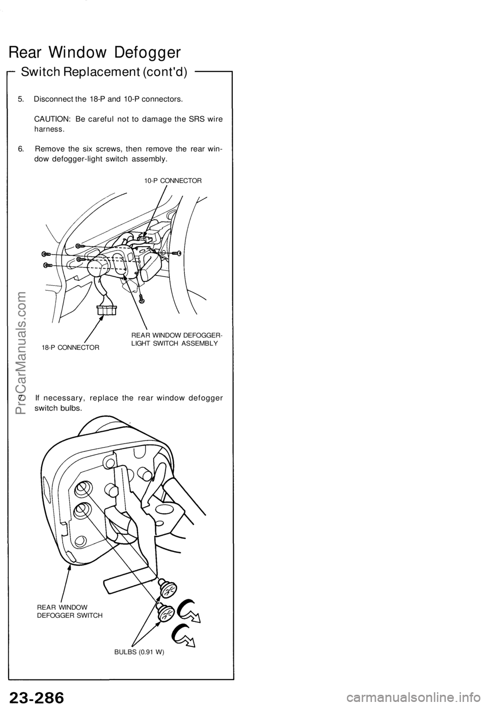
5. Disconnect the 18-P and 10-P connectors.
CAUTION: Be careful not to damage the SRS wire
harness.
6. Remove the six screws, then remove the rear win-
dow defogger-light switch assembly.
10-P CONNECTOR
18-P CONNECTOR
REAR WINDOW DEFOGGER-
LIGHT SWITCH ASSEMBLY
7. If necessary, replace the rear window defogger
switch bulbs.
REAR WINDOW
DEFOGGER SWITCH
BULBS (0.91 W)ProCarManuals.com
Page 923 of 1640
Rear Windo w Defogge r
Relay Tes t
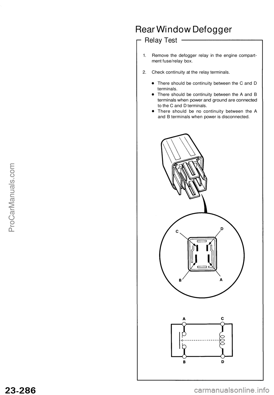
1. Remov e th e defogge r rela y i n th e engin e compart -
men t fuse/rela y box .
2 . Chec k continuit y a t th e rela y terminals .
Ther e shoul d b e continuit y betwee n th e C an d D
terminals .
Ther e shoul d b e continuity between th e A an d B
terminal s whe n powe r an d groun d ar e connecte d
to th e C an d D terminals .
Ther e shoul d b e n o continuit y betwee n th e A
an d B terminal s whe n powe r i s disconnected .
ProCarManuals.com
Page 924 of 1640
Switch Tes t
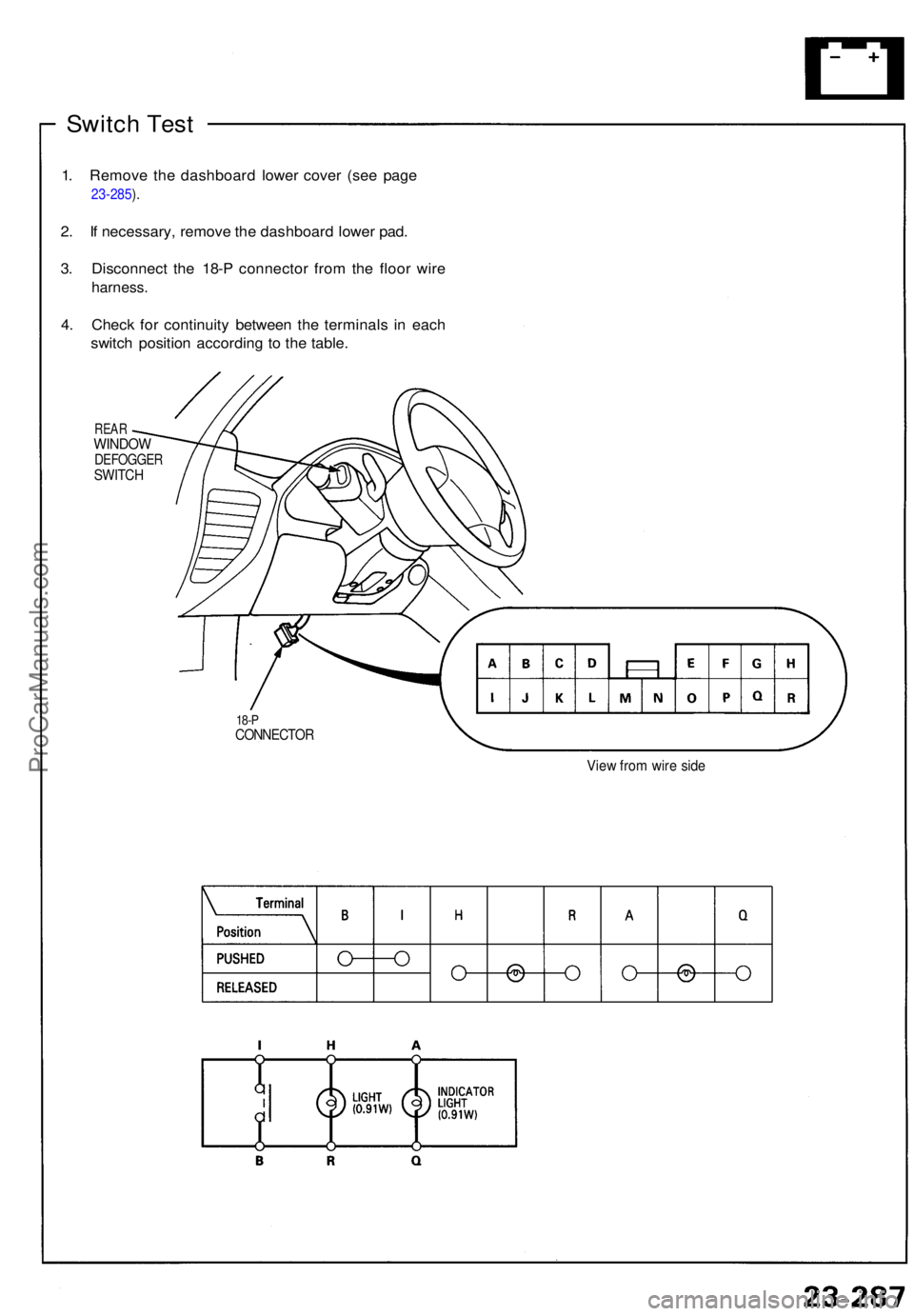
1. Remov e th e dashboar d lowe r cove r (se e pag e
23-285 ).
2 . I f necessary, remove th e dashboar d lowe r pad .
3 . Disconnec t th e 18- P connecto r fro m th e floo r wir e
harness .
4. Chec k fo r continuit y betwee n th e terminal s i n eac h
switc h positio n accordin g t o th e table .
REARWINDO WDEFOGGE RSWITCH
18-PCONNECTO R
View fro m wir e sid e
ProCarManuals.com
Page 925 of 1640
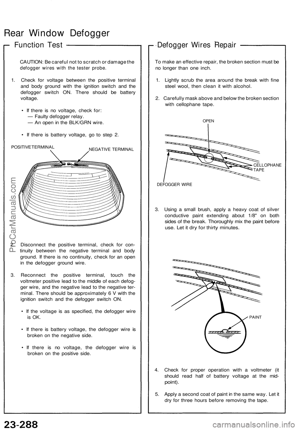
Rear Window Defogger
Function Test
CAUTION: Be careful not to scratch or damage the
defogger wires with the tester probe.
1. Check for voltage between the positive terminal
and body ground with the ignition switch and the
defogger switch ON. There should be battery
voltage.
• If there is no voltage, check for:
— Faulty defogger relay.
— An open in the BLK/GRN wire.
• If there is battery voltage, go to step 2.
POSITIVE TERMINAL
NEGATIVE TERMINAL
2. Disconnect the positive terminal, check for con-
tinuity between the negative terminal and body
ground. If there is no continuity, check for an open
in the defogger ground wire.
3. Reconnect the positive terminal, touch the
voltmeter positive lead to the middle of each defog-
ger wire, and the negative lead to the negative ter-
minal. There should be approximately 6 V with the
ignition switch and the defogger switch ON.
• If the voltage is as specified, the defogger wire
is OK.
• If there is battery voltage, the defogger wire is
broken on the negative side.
• If there is no voltage, the defogger wire is
broken on the positive side.
Defogger Wires Repair
To make an effective repair, the broken section must be
no longer than one inch.
1. Lightly scrub the area around the break with fine
steel wool, then clean it with alcohol.
2. Carefully mask above and below the broken section
with cellophane tape.
OPEN
CELLOPHANE
TAPE
DEFOGGER WIRE
3. Using a small brush, apply a heavy coat of silver
conductive paint extending about 1/8" on both
sides of the break. Thoroughly mix the paint before
use. Let it dry for thirty minutes.
PAINT
4. Check for proper operation with a voltmeter (it
should read half of battery voltage at the mid-
point).
5. Apply a second coat of paint in the same way. Let it
dry for three hours before removing the tape.ProCarManuals.com
Page 926 of 1640
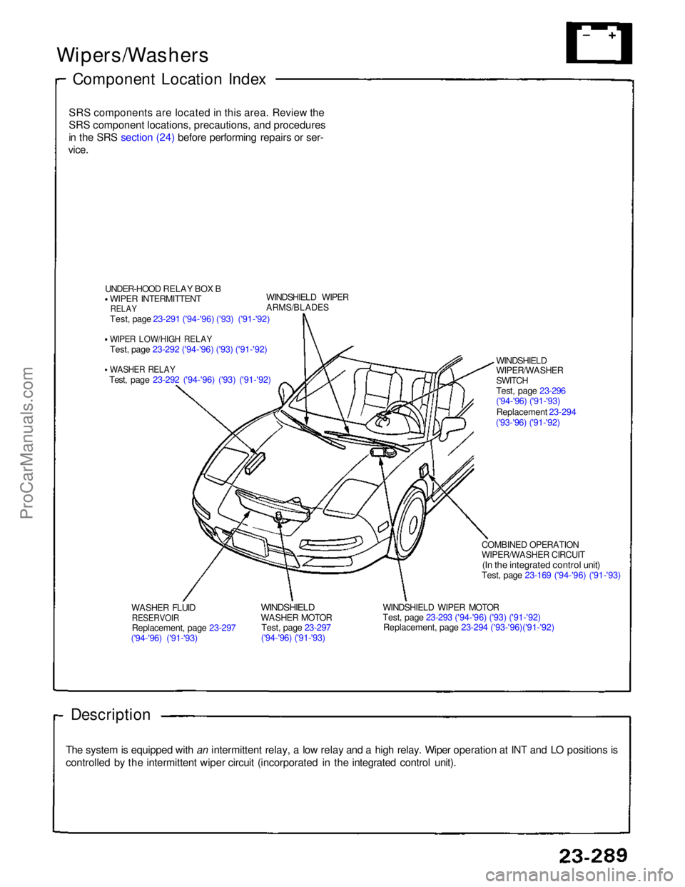
Wipers/Washers
Component Location Index
SRS components are located in this area. Review theSRS component locations, precautions, and procedures
in the SRS section (24) before performing repairs or ser-
vice.
UNDER-HOOD RELAY BOX BWIPER INTERMITTENT
RELAY
Test, page 23-291 ('94-'96) ('93) ('91-'92)
WIPER LOW/HIGH RELAY
Test, page 23-292 ('94-'96) ('93) ('91-'92)
WASHER RELAY
Test, page 23-292 ('94-'96) ('93) ('91-'92) WINDSHIELD WIPER
ARMS/BLADES
WASHER FLUID
RESERVOIR
Replacement, page 23-297
('94-'96) ('91-'93)
WINDSHIELD
WASHER MOTOR
Test, page 23-297
('94-'96) ('91-'93) WINDSHIELD WIPER MOTOR
Test, page 23-293 ('94-'96) ('93) ('91-'92)
Replacement, page 23-294 ('93-'96)('91-'92) COMBINED OPERATION
WIPER/WASHER CIRCUIT
(In the integrated control unit)
Test, page 23-169 ('94-'96) ('91-'93)
Description
The system is equipped with an intermittent relay, a low relay and a high relay. Wiper operation at INT and LO positions is
controlled by the intermittent wiper circuit (incorporated in the integrated control unit). WINDSHIELD
WIPER/WASHER
SWITCH
Test, page 23-296
('94-'96) ('91-'93)
Replacement 23-294
('93-'96) ('91-'92)ProCarManuals.com
Page 927 of 1640
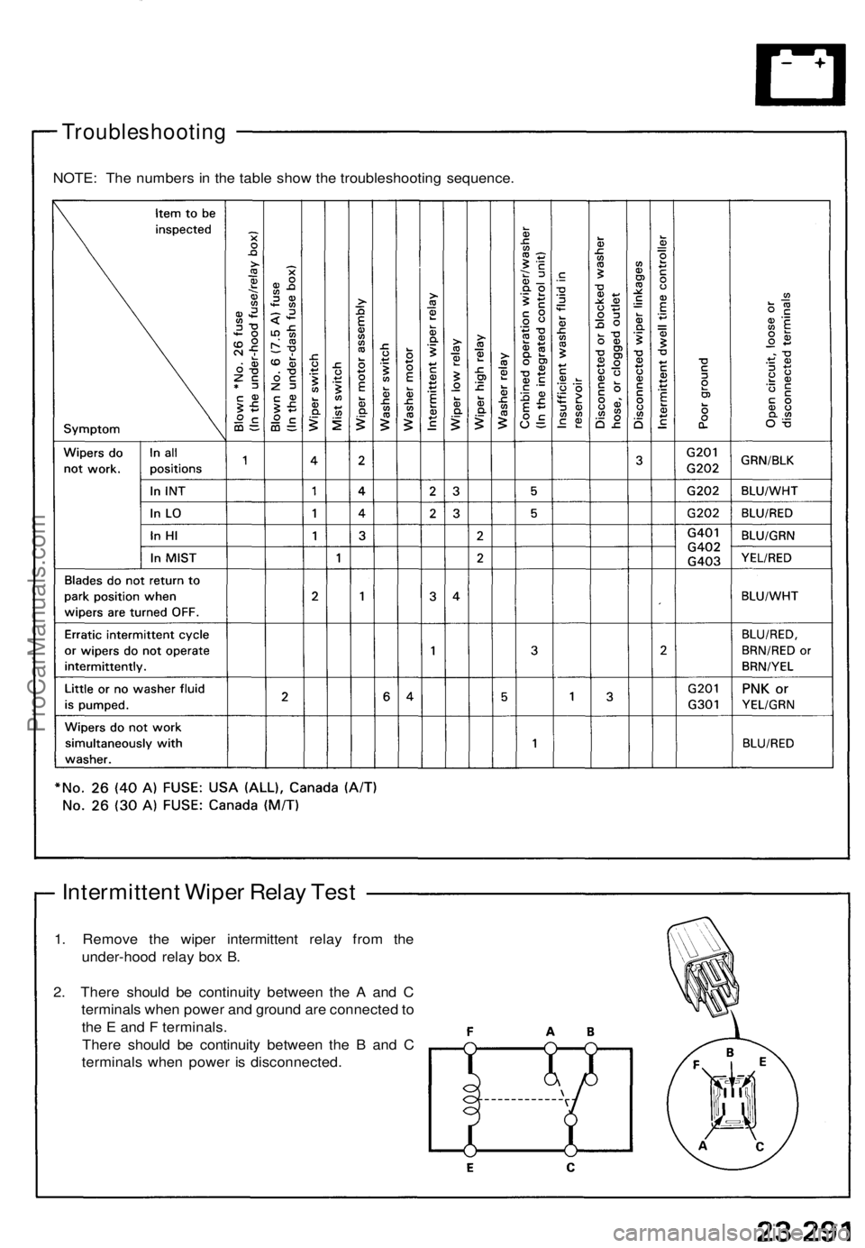
Troubleshooting
Intermittent Wiper Relay Test
1. Remove the wiper intermittent relay from the
under-hood relay box B.
2. There should be continuity between the A and C
terminals when power and ground are connected to
the E and F terminals.
There should be continuity between the B and C
terminals when power is disconnected.
NOTE: The numbers in the table show the troubleshooting sequence.ProCarManuals.com
Page 928 of 1640
Wipers/Washers
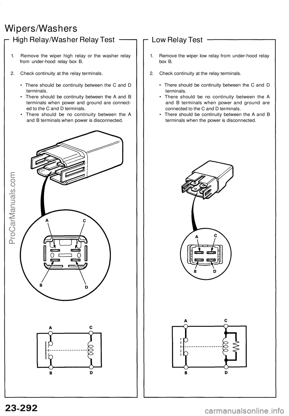
High Relay/Washer Relay Test
1. Remove the wiper high relay or the washer relay
from under-hood relay box B.
2. Check continuity at the relay terminals.
• There should be continuity between the C and D
terminals.
• There should be continuity between the A and B
terminals when power and ground are connect-
ed to the C and D terminals.
• There should be no continuity between the A
and B terminals when power is disconnected.
Low Relay Test
1. Remove the wiper low relay from under-hood relay
box B.
2. Check continuity at the relay terminals.
• There should be continuity between the C and D
terminals.
• There should be no continuity between the A
and B terminals when power and ground are
connected to the C and D terminals.
• There should be continuity between the A and B
terminals when the power is disconnected.ProCarManuals.com
Page 929 of 1640
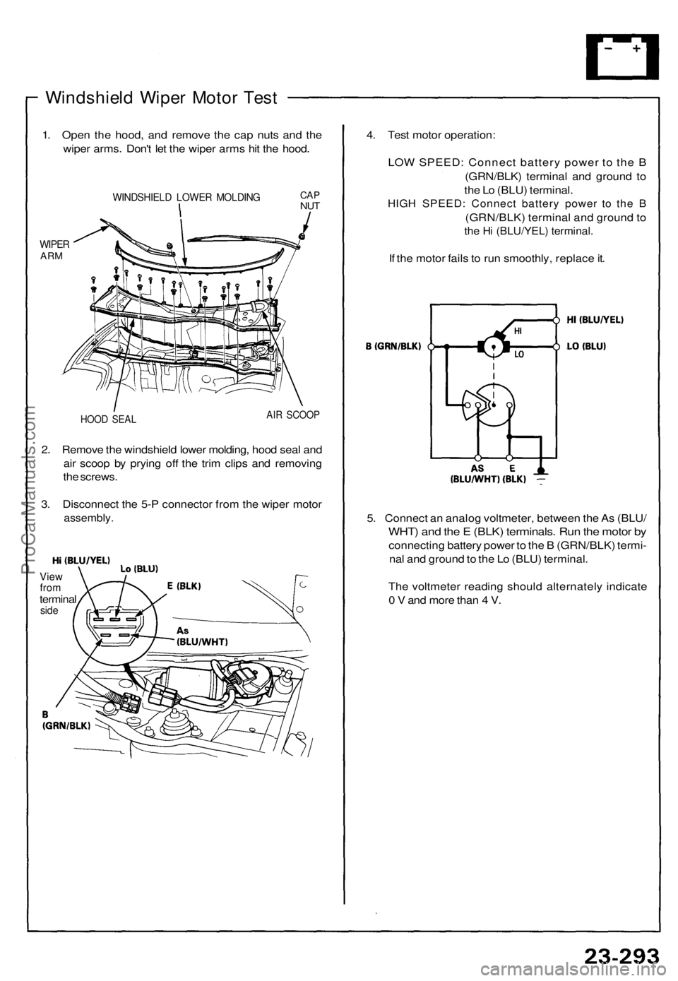
Windshield Wiper Motor Test
1. Open the hood, and remove the cap nuts and the
wiper arms. Don't let the wiper arms hit the hood.
WIPER
ARM
WINDSHIELD LOWER MOLDING
HOOD SEAL
AIR SCOOP
2. Remove the windshield lower molding, hood seal and
air scoop by prying off the trim clips and removing
the screws.
3. Disconnect the 5-P connector from the wiper motor
assembly.
View
from
terminal
side
4. Test motor operation:
LOW SPEED: Connect battery power to the B
(GRN/BLK) terminal and ground to
the Lo (BLU) terminal.
HIGH SPEED: Connect battery power to the B
(GRN/BLK) terminal and ground to
the Hi (BLU/YEL) terminal.
If the motor fails to run smoothly, replace it.
5. Connect an analog voltmeter, between the As (BLU/
WHT) and the E (BLK) terminals. Run the motor by
connecting battery power to the B (GRN/BLK) termi-
nal and ground to the Lo (BLU) terminal.
The voltmeter reading should alternately indicate
0 V and more than 4 V.
CAP
NUTProCarManuals.com
Page 930 of 1640
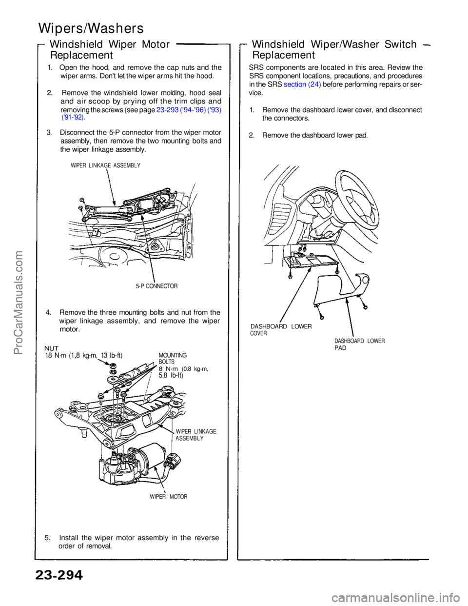
Wipers/Washers
Windshield Wiper MotorReplacement
1. Open the hood, and remove the cap nuts and the wiper arms. Don't let the wiper arms hit the hood.
2. Remove the windshield lower molding, hood seal
and air scoop by prying off the trim clips and
removing the screws (see page 23-293 ('94-'96) ('93)
('91-'92).
3. Disconnect the 5-P connector from the wiper motor assembly, then remove the two mounting bolts and
the wiper linkage assembly.
WIPER LINKAGE ASSEMBLY
5-P CONNECTOR
4. Remove the three mounting bolts and nut from the wiper linkage assembly, and remove the wiper
motor.
MOUNTING
BOLTS
8 N·m
(0.8 kg-m,
5.8 Ib-ft)
NUT
18 N·m (1,8 kg-m, 13 Ib-ft)
WIPER LINKAGE
ASSEMBLY
WIPER MOTOR
5. Install the wiper motor assembly in the reverse order of removal.
DASHBOARD LOWER
PAD
DASHBOARD LOWER
COVER
Windshield Wiper/Washer Switch
Replacement
SRS components are located in this area. Review the SRS component locations, precautions, and procedures
in the SRS section (24) before performing repairs or ser-
vice.
1. Remove the dashboard lower cover, and disconnect the connectors.
2. Remove the dashboard lower pad.ProCarManuals.com