ACURA NSX 1991 Service Repair Manual
Manufacturer: ACURA, Model Year: 1991,
Model line: NSX,
Model: ACURA NSX 1991
Pages: 1640, PDF Size: 60.48 MB
ACURA NSX 1991 Service Repair Manual
NSX 1991
ACURA
ACURA
https://www.carmanualsonline.info/img/32/56988/w960_56988-0.png
ACURA NSX 1991 Service Repair Manual
Trending: manual radio set, windshield wipers, tire type, recommended oil, spare tire location, center console, set clock
Page 911 of 1640
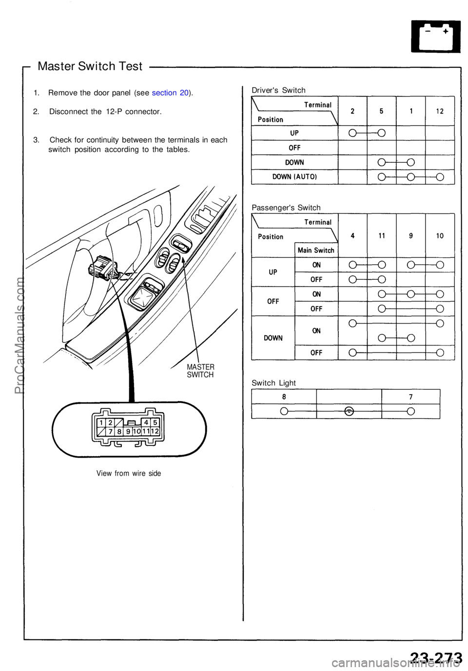
Master Switc h Tes t
1. Remov e th e doo r pane l (se e sectio n 20 ).
2 . Disconnec t th e 12- P connector .
3 . Chec k fo r continuit y betwee n th e terminal s i n eac h
switc h positio n accordin g t o th e tables .
View fro m wir e sid e
MASTE RSWITCH
Driver's Switc h
Switc h Ligh t
Passenger'
s Switc h
ProCarManuals.com
Page 912 of 1640
Power Window s
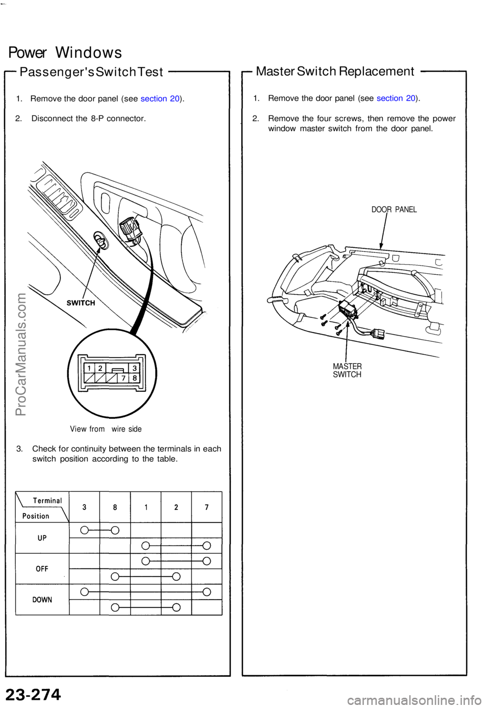
Passenger' s Switc h Tes t
1. Remov e th e doo r pane l (se e sectio n 20 ).
2 . Disconnec t th e 8- P connector .
View fro m wir e sid e
3. Chec k fo r continuit y betwee n th e terminal s i n eac h
switc h positio n accordin g t o th e table.
Maste r Switc h Replacemen t
1. Remov e th e doo r pane l (se e sectio n 20 ).
2 . Remov e th e fou r screws , the n remov e th e powe r
windo w maste r switc h fro m th e doo r panel .
DOOR PANE L
MASTE RSWITCH
ProCarManuals.com
Page 913 of 1640
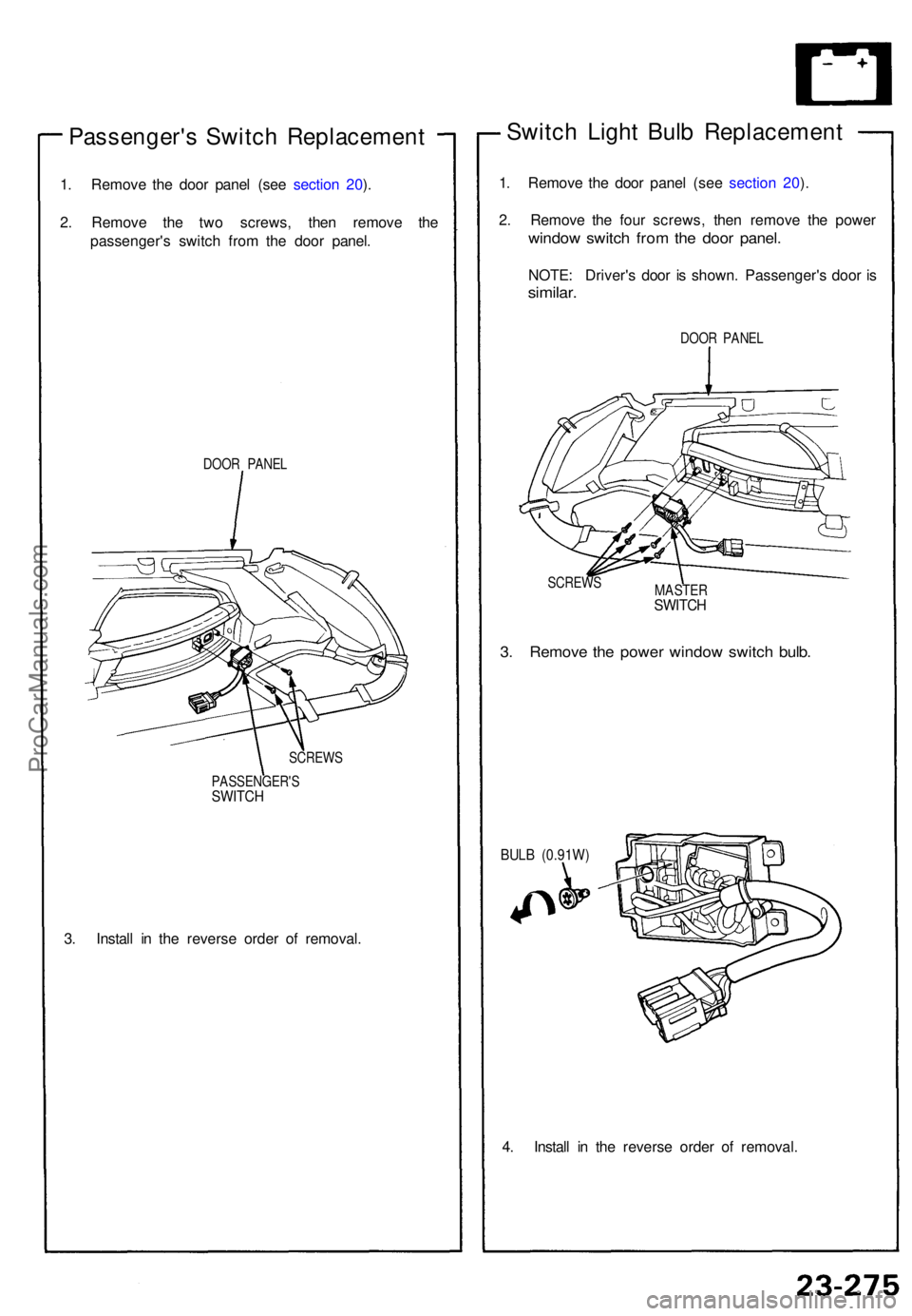
Passenger's Switc h Replacemen t
1. Remov e th e doo r pane l (se e sectio n 20 ).
2 . Remov e th e tw o screws , the n remov e th e
passenger' s switc h fro m th e doo r panel .
DOOR PANE L
SCREW S
PASSENGER' S
SWITCH
3. Instal l i n th e revers e orde r o f removal .
Switch Ligh t Bul b Replacemen t
1. Remov e th e doo r pane l (se e sectio n 20 ).
2 . Remov e th e fou r screws , the n remov e th e powe r
window switc h fro m th e doo r panel .
NOTE: Driver' s doo r i s shown . Passenger' s doo r i s
similar .
DOOR PANE L
SCREW S
MASTERSWITCH
3. Remov e th e powe r windo w switc h bulb .
BULB (0.91W )
4. Instal l i n th e revers e orde r o f removal .
ProCarManuals.com
Page 914 of 1640
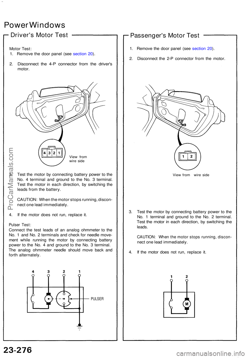
Power Window s
Driver's Moto r Tes t
Moto r Test :
1 . Remov e th e doo r pane l (se e sectio n 20 ).
2 . Disconnec t th e 4- P connecto r fro m th e driver' s
motor.
View fro m
wir e sid e
3. Tes t th e moto r b y connectin g batter y powe r t o th e
No . 4 termina l an d groun d t o th e No . 3 terminal .
Tes t th e moto r i n eac h direction , b y switchin g th e
lead s fro m th e battery .
CAUTION : Whe n th e moto r stop s running , discon -
nec t on e lea d immediately .
4 . I f th e moto r doe s no t run , replac e it .
Pulse r Test :
Connec t th e tes t lead s of an analo g ohmmete r t o th e
No . 1 an d No . 2 terminal s an d chec k fo r needl e move -
men t whil e runnin g th e moto r b y connectin g batter y
powe r t o th e No . 4 an d groun d t o th e No . 3 terminal .
Th e analo g ohmmete r needl e shoul d mov e bac k an d
fort h alternately .
PULSER
Passenger' s Moto r Tes t
1. Remov e th e doo r pane l (se e sectio n 20 ).
2 . Disconnec t th e 2- P connecto r fro m th e motor .
View fro m wir e sid e
3. Tes t th e moto r b y connectin g batter y powe r t o th e
No . 1 termina l an d groun d t o th e No . 2 terminal .
Test th e moto r i n eac h direction , b y switchin g th e
leads .
CAUTION : Whe n th e moto r stop s running , discon -
nect on e lea d immediately .
4 . I f th e moto r doe s no t run , replac e it .
ProCarManuals.com
Page 915 of 1640
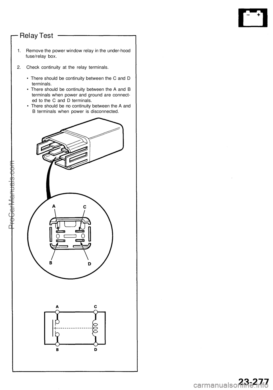
Relay Test
1. Remove the power window relay in the under-hood
fuse/relay box.
2. Check continuity at the relay terminals.
• There should be continuity between the C and D
terminals.
• There should be continuity between the A and B
terminals when power and ground are connect-
ed to the C and D terminals.
• There should be no continuity between the A and
B terminals when power is disconnected.ProCarManuals.com
Page 916 of 1640
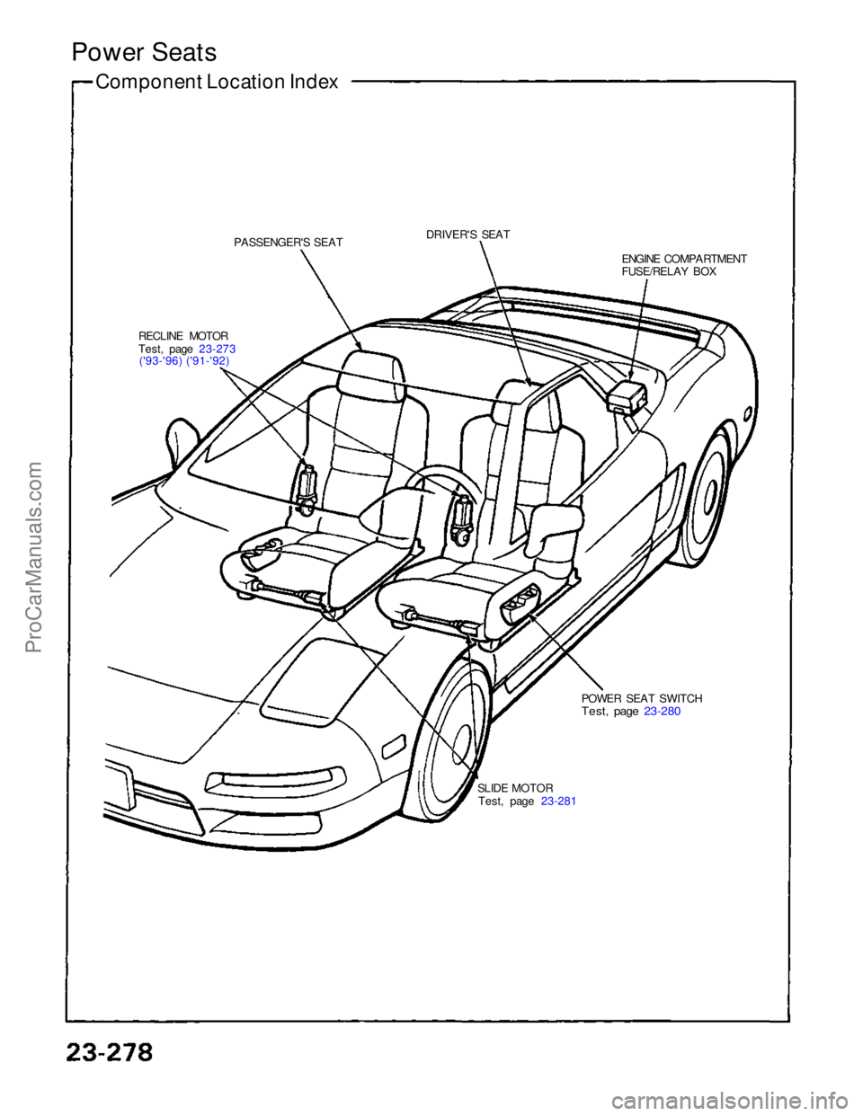
Power Seats
Component Location Index
PASSENGER'S SEAT
DRIVER'S SEAT
RECLINE MOTOR
Test, page 23-273 ('93-'96) ('91-'92) ENGINE COMPARTMENT
FUSE/RELAY BOX
SLIDE MOTOR Test, page 23-281 POWER SEAT SWITCH
Test, page 23-280ProCarManuals.com
Page 917 of 1640
Power Seats
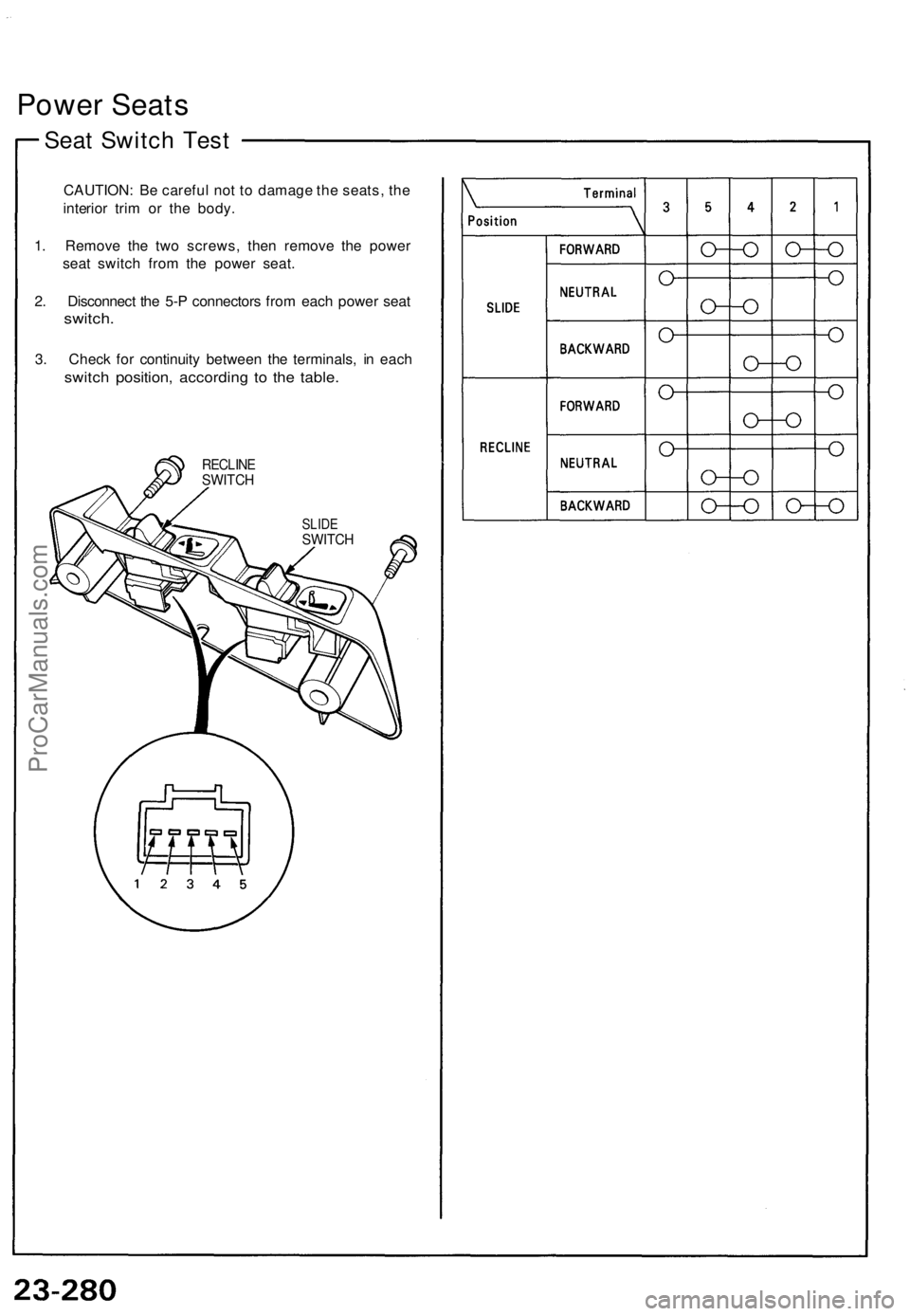
Seat Switch Test
CAUTION: Be careful not to damage the seats, the
interior trim or the body.
1. Remove the two screws, then remove the power
seat switch from the power seat.
2. Disconnect the 5-P connectors from each power seat
switch.
3. Check for continuity between the terminals, in each
switch position, according to the table.
RECLINE
SWITCH
SLIDE
SWITCHProCarManuals.com
Page 918 of 1640
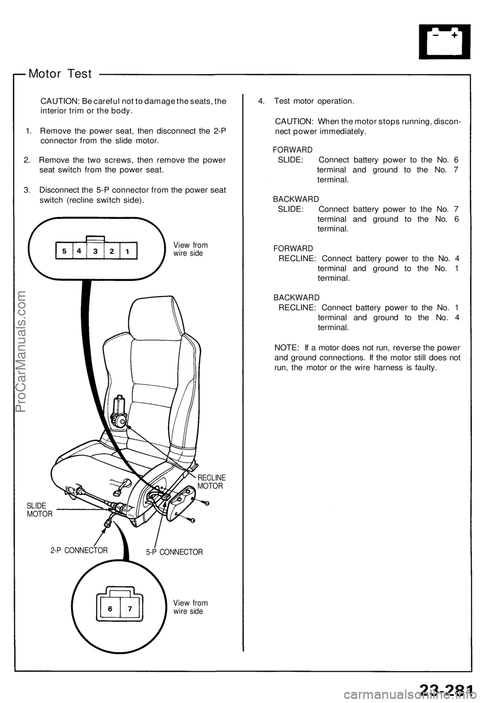
Motor Test
CAUTION: Be careful not to damage the seats, the
interior trim or the body.
1. Remove the power seat, then disconnect the 2-P
connector from the slide motor.
2. Remove the two screws, then remove the power
seat switch from the power seat.
3. Disconnect the 5-P connector from the power seat
switch (recline switch side).
View from
wire side
SLIDE
MOTOR
RECLINE
MOTOR
View from
wire side
4. Test motor operation.
CAUTION: When the motor stops running, discon-
nect power immediately.
FORWARD
SLIDE: Connect battery power to the No. 6
terminal and ground to the No. 7
terminal.
BACKWARD
SLIDE: Connect battery power to the No. 7
terminal and ground to the No. 6
terminal.
FORWARD
RECLINE: Connect battery power to the No. 4
terminal and ground to the No. 1
terminal.
BACKWARD
RECLINE: Connect battery power to the No. 1
terminal and ground to the No. 4
terminal.
NOTE: If a motor does not run, reverse the power
and ground connections. If the motor still does not
run, the motor or the wire harness is faulty.
5-P CONNECTOR
2-P CONNECTORProCarManuals.com
Page 919 of 1640
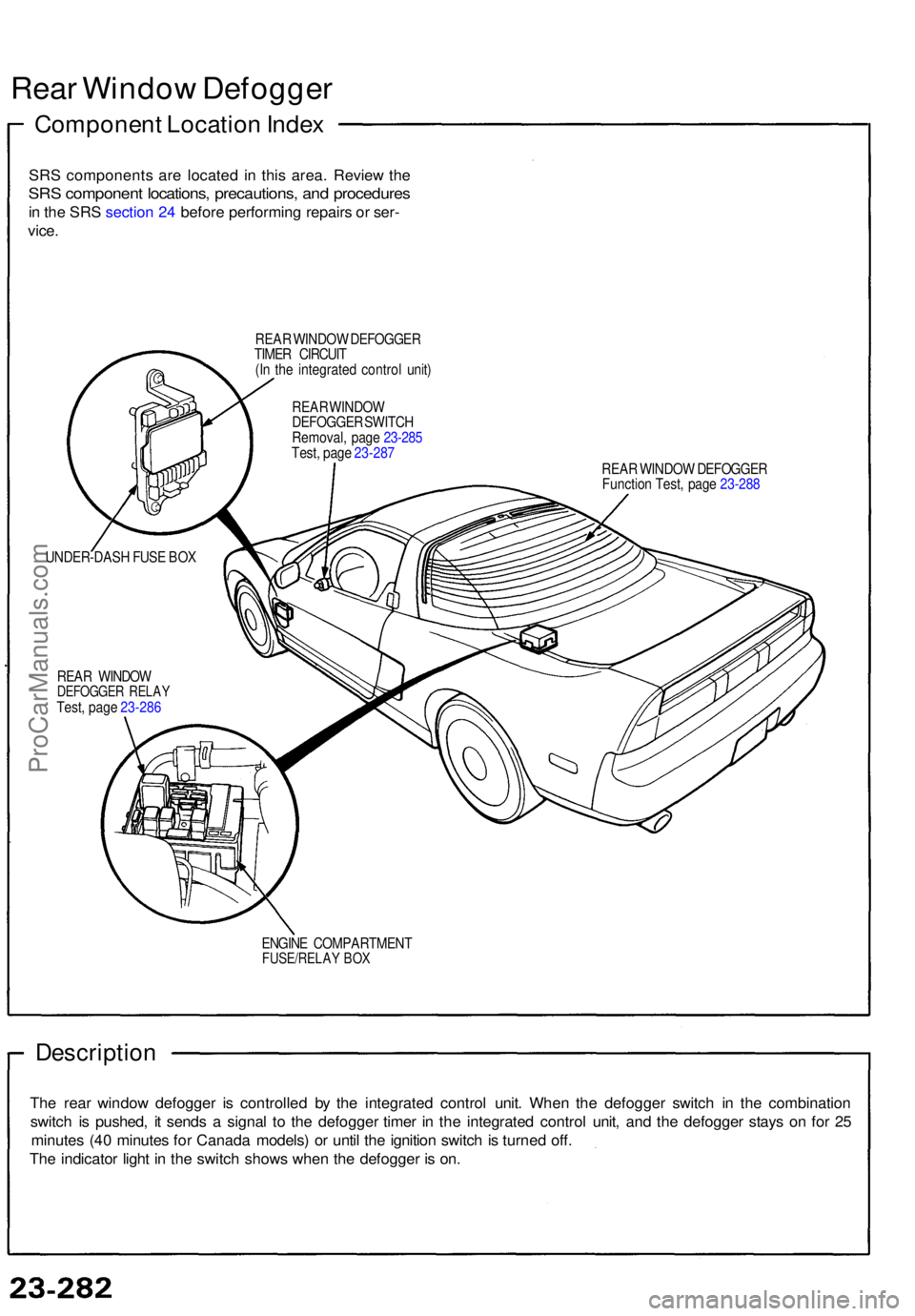
Rear Windo w Defogge r
Componen t Locatio n Inde x
SRS component s ar e locate d i n thi s area . Revie w th e
SR S componen t locations , precautions , an d procedure s
in th e SR S sectio n 24 befor e performin g repair s o r ser -
vice .
REA R WINDO W DEFOGGE R
TIME R CIRCUI T
(I n th e integrate d contro l unit )
REAR WINDO W DEFOGGE R
Functio n Test , pag e 23-28 8
UNDER-DAS H FUS E BO X
REA R WINDO W
DEFOGGE R RELA YTest, pag e 23-28 6
ENGINE COMPARTMEN T
FUSE/RELAY BO X
Descriptio n
The rea r windo w defogge r i s controlle d b y th e integrate d contro l unit . Whe n th e defogge r switc h i n th e combinatio n
switc h i s pushed , i t send s a signa l t o th e defogge r time r i n th e integrate d contro l unit , an d th e defogge r stay s o n fo r 2 5
minute s (4 0 minute s fo r Canad a models ) o r unti l th e ignitio n switc h is turne d off .
Th e indicato r ligh t i n th e switc h show s whe n th e defogge r i s on .
REA R WINDO W
DEFOGGE R SWITC H
Removal , pag e 23-28 5
Test , pag e 23-28 7
ProCarManuals.com
Page 920 of 1640
Troubleshooting
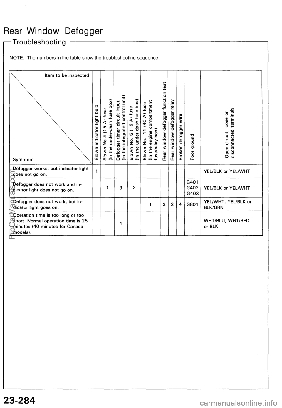
Rear Window Defogger
NOTE: The numbers in the table show the troubleshooting sequence.ProCarManuals.com
Trending: center console, air filter, diagram, service reset, manual transmission, child seat, hood open
