ACURA NSX 1991 Service Repair Manual
Manufacturer: ACURA, Model Year: 1991, Model line: NSX, Model: ACURA NSX 1991Pages: 1640, PDF Size: 60.48 MB
Page 981 of 1640
Cylinder Head
Camshaft
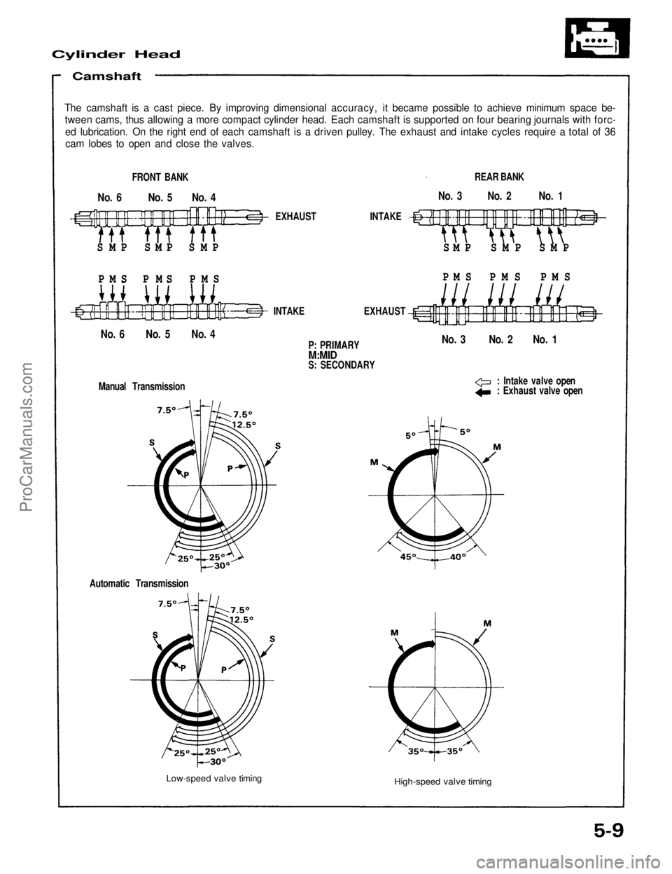
The camshaft is a cast piece. By improving dimensional accuracy, it became possible to achieve minimum space be-
tween cams, thus allowing a more compact cylinder head. Each camshaft is supported on four bearing journals with forc-
ed lubrication. On the right end of each camshaft is a driven pulley. The exhaust and intake cycles require a total of 36
cam lobes to open and close the valves.
FRONT BANK
No. 6 No. 5 No. 4
S M P S M P S M P
P M S P M S P M S
EXHAUST INTAKE
S M P S M P S M P
P M S P M S P M S
REAR BANK
No. 3 No. 2 No. 1
No. 3 No. 2 No. 1
No. 6 No. 5 No. 4
INTAKE EXHAUST
P: PRIMARY
M:MID
S: SECONDARY
: Intake valve open
: Exhaust valve open
Manual Transmission
Automatic Transmission
Low-speed valve timing
High-speed valve timingProCarManuals.com
Page 982 of 1640
Lubrication System
Lubrication Flow
VTEC SOLENOID VALVE
ROCKER SHAFT
ORIFICES
M
M
M
CYLINDER HEAD
ORIFICE
OIL SCREEN
OIL PUMP
RELIEF VALVE
OIL FILTER
ENGINE COOLANT
ENGINE OIL
COOLER
CYLINDER HEAD
ORIFICE
ROCKER SHAFT
ORIFICES
P: PRIMARY
M: MID
S: SECONDARY
M
M
M
VTEC SOLENOID VALVE
No. 3
M
M
M
No. 1
No. 2
M
M
M
No. 6 No. 5 No. 4
Front
Rear
CRANKSHAFT
MAIN JOURNAL
MAIN BEARING
CAP BRIDGEProCarManuals.com
Page 983 of 1640
Exhaust System
Dual Exhaust System
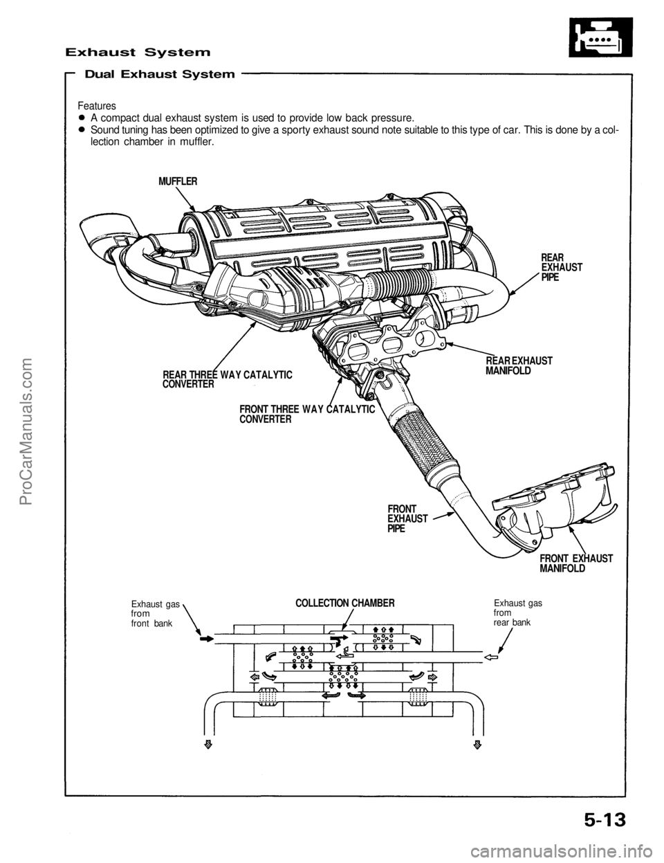
A compact dual exhaust system is used to provide low back pressure.
Sound tuning has been optimized to give a sporty exhaust sound note suitable to this type of car. This is done by a col-
lection chamber in muffler.
MUFFLER
REAR
EXHAUST
PIPE
REAR EXHAUST
MANIFOLD
FRONT THREE WAY CATALYTIC
CONVERTER
REAR THREE WAY CATALYTIC
CONVERTER
FRONT
EXHAUST
PIPE
FRONT EXHAUST
MANIFOLD
Exhaust gas
from
rear bank
COLLECTION CHAMBER
Exhaust gas
from
front bank
FeaturesProCarManuals.com
Page 984 of 1640
Cooling
Cooling System
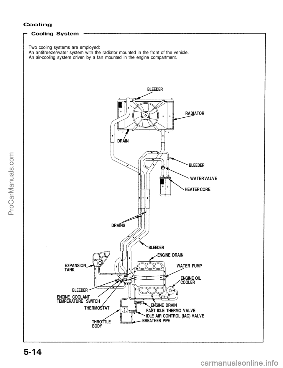
Two cooling systems are employed:
An antifreeze/water system with the radiator mounted in the front of the vehicle.
An air-cooling system driven by a fan mounted in the engine compartment.
BLEEDER
RADIATOR
BLEEDER
WATER VALVE
HEATER CORE
DRAIN
DRAINS
BLEEDER
ENGINE DRAIN
WATER PUMP
ENGINE OIL
COOLER
ENGINE DRAIN
FAST IDLE THERMO VALVE
IDLE AIR CONTROL (IAC) VALVE
BREATHER PIPE
THROTTLE
BODY
THERMOSTAT
TEMPERATURE SWITCH
ENGINE COOLANT
BLEEDER
EXPANSION
TANKProCarManuals.com
Page 985 of 1640
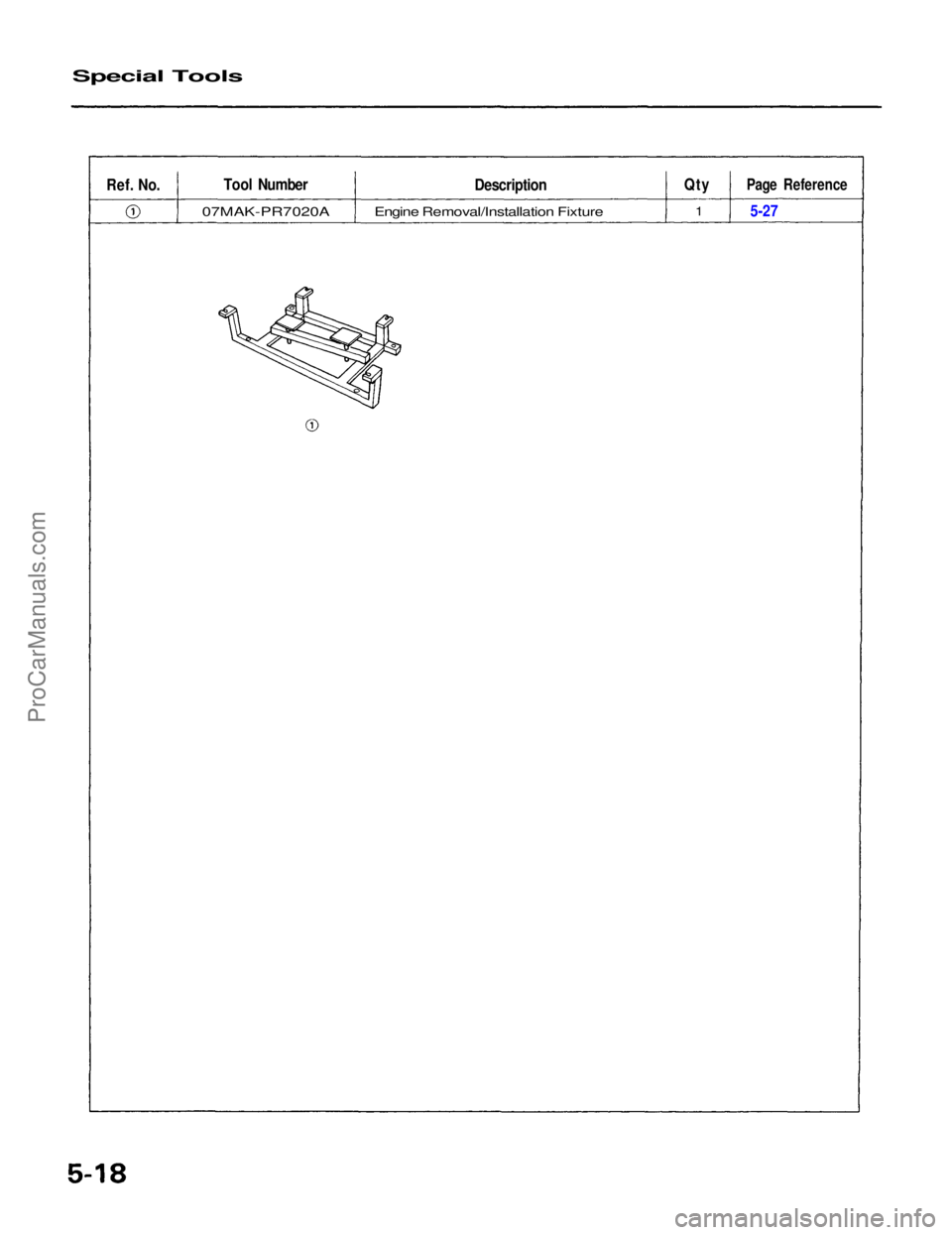
Special Tools
Ref.
No.
Tool Number
07MAK-PR7020A
Description
Engine Removal/Installation Fixture
Qty
1
Page Reference
5-27ProCarManuals.com
Page 986 of 1640
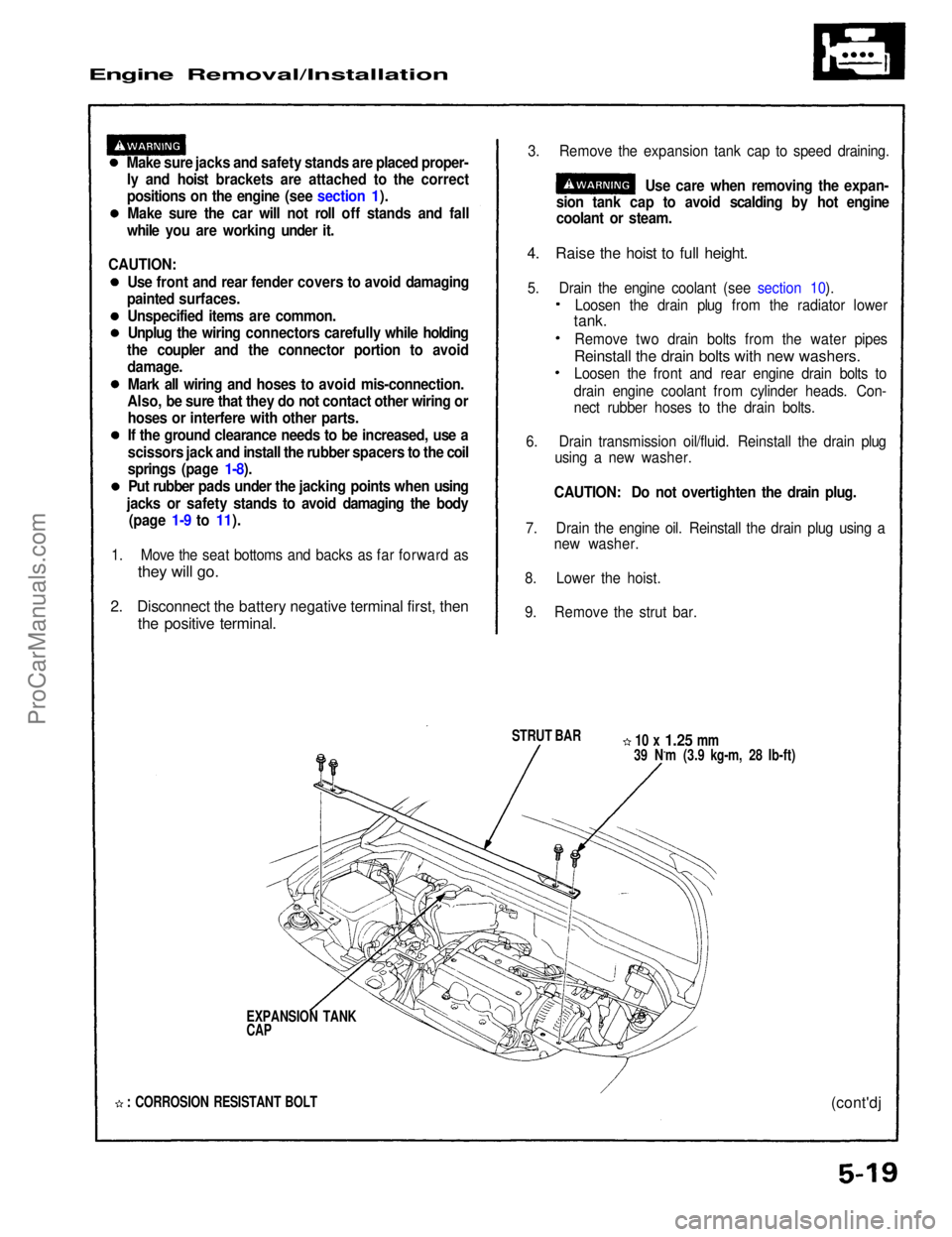
Engine Removal/Installation
Make sure jacks and safety stands are placed proper-ly and hoist brackets are attached to the correct
positions on the engine (see section 1).
Make sure the car will not roll off stands and fall
while you are working under it. 3. Remove the expansion tank cap to speed draining.
Use care when removing the expan-
sion tank cap to avoid scalding by hot engine
coolant or steam.
4. Raise the hoist to full height.
5. Drain the engine coolant (see section 10).
STRUT BAR
10 x
1.25
mm
39 N.m (3.9 kg-m, 28 Ib-ft)
EXPANSION TANK
CAP
: CORROSION RESISTANT BOLT
(cont'dj
1. Move the seat bottoms and backs as far forward as
they will go.
2. Disconnect the battery negative terminal first, then
the positive terminal.
Loosen the drain plug from the radiator lower
tank.
Remove two drain bolts from the water pipes
Reinstall the drain bolts with new washers.
Loosen the front and rear engine drain bolts to
drain engine coolant from cylinder heads. Con-
nect rubber hoses to the drain bolts.
6. Drain transmission oil/fluid. Reinstall the drain plug using a new washer.
CAUTION: Do not overtighten the drain plug.
7. Drain the engine oil. Reinstall the drain plug using a new washer.
8. Lower the hoist.
9. Remove the strut bar.
CAUTION:
Use front and rear fender covers to avoid damaging
painted surfaces.
Unspecified items are common.Unplug the wiring connectors carefully while holding
the coupler and the connector portion to avoid damage.
Mark all wiring and hoses to avoid mis-connection.
Also, be sure that they do not contact other wiring or hoses or interfere with other parts.
If the ground clearance needs to be increased, use a
scissors jack and install the rubber spacers to the coil
springs (page 1-8).
Put rubber pads under the jacking points when using
jacks or safety stands to avoid damaging the body (page 1-9 to 11).ProCarManuals.com
Page 987 of 1640
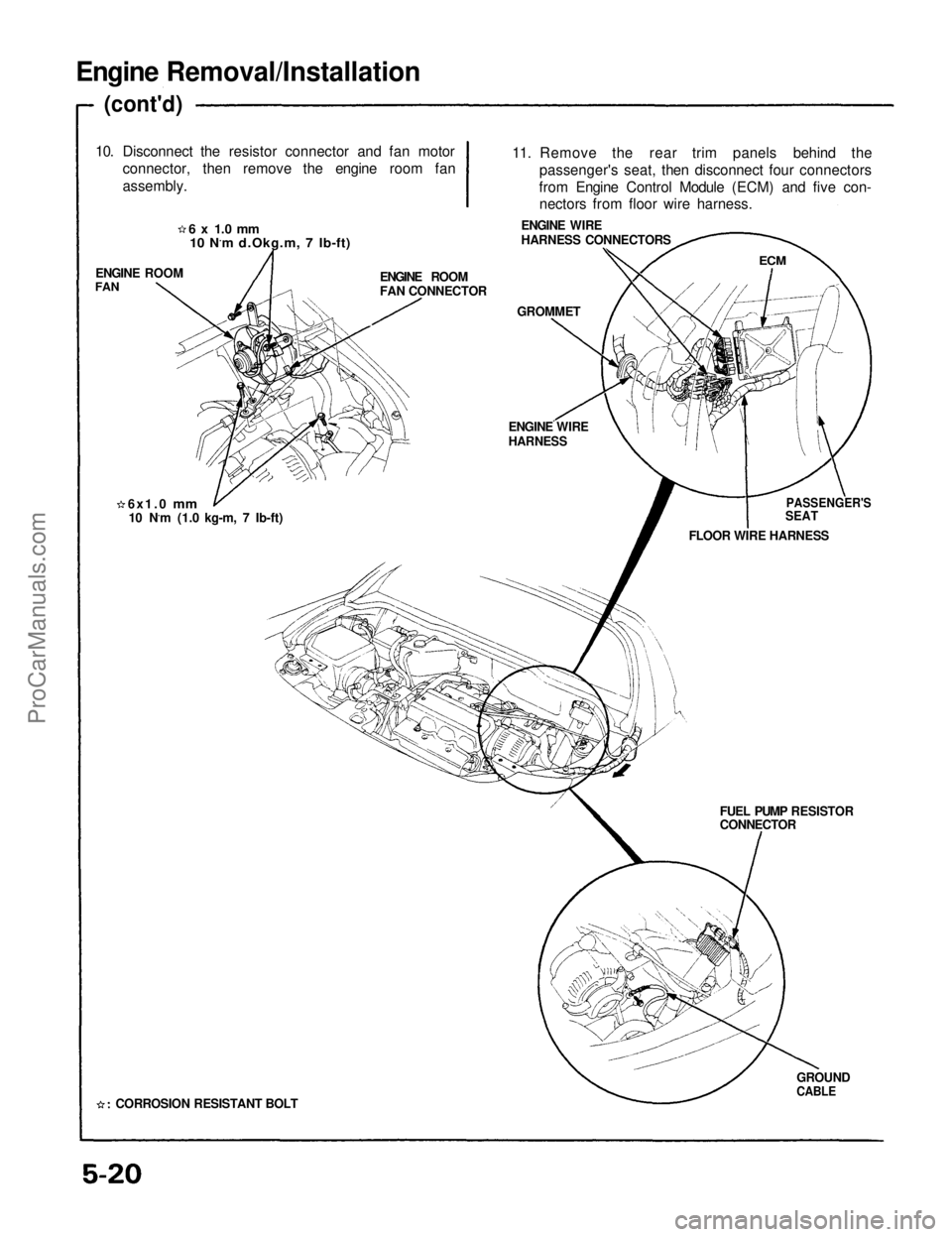
Engine Removal/Installation
(cont'd)
10. Disconnect the resistor connector and fan motor connector, then remove the engine room fan
assembly.
ENGINE ROOM
FAN
ENGINE ROOM
FAN CONNECTOR
GROMMET
11. Remove the rear trim panels behind the
passenger's seat, then disconnect four connectors
from Engine Control Module (ECM) and five con- nectors from floor wire harness.
ENGINE WIRE
HARNESS CONNECTORS
ECM
PASSENGER'S
SEAT
FLOOR WIRE HARNESS
ENGINE WIRE
HARNESS
FUEL PUMP RESISTOR
CONNECTORGROUND
CABLE
6x1.0
mm
10 N.m (1.0 kg-m, 7 Ib-ft)
CORROSION RESISTANT BOLT
6 x 1.0 mm
10 N.m d.Okg.m, 7 Ib-ft)ProCarManuals.com
Page 988 of 1640
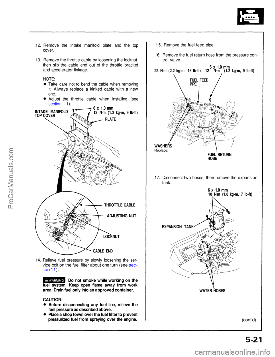
12. Remove the intake manifold plate and the top
cover.
13. Remove the throttle cable by loosening the locknut, then slip the cable end out of the throttle bracketand accelerator linkage.
INTAKE MANIFOLD
TOP COVER
6 x 1.0 mm
12 N .
m (1.2 kg-m, 9 Ib-ft)
PLATE
ADJUSTING NUT
LOCKNUT
CABLE END
14. Relieve fuel pressure by slowly loosening the ser-
vice bolt on the fuel filter about one turn (see sec-
tion 11 ).
1 5. Remove the fuel feed pipe.
16. Remove the fuel return hose from the pressure con- trol valve.
6 x 1.0 mm
22 N .
m (2.2 kg-m. 16 Ib-ft) 12 N .
m (1.2 kg-m, 9 Ib-ft)
FUEL FEED
PIPE
WASHERS
Replace.
FUEL RETURN
HOSE
17. Disconnect two hoses, then remove the expansion tank.
6 x 1.0 mm
10 N .
m (1.0 kg-m, 7 Ib-ft)
EXPANSION TANK
WATER HOSES
(cont'd)
Do not smoke while working on the
fuel system. Keep open flame away from work
area. Drain fuel only into an approved container.
CAUTION:
THROTTLE CABLE
NOTE:
Take care not to bend the cable when removingit. Always replace a kinked cable with a new
one.
Adjust the throttle cable when installing (see
section 11).
Before disconnecting any fuel line, relieve the
fuel pressure as described above.
Place a shop towel over the fuel filter to prevent
pressurized fuel from spraying over the engine.ProCarManuals.com
Page 989 of 1640
Engine Removal/Installation
(cont'd)
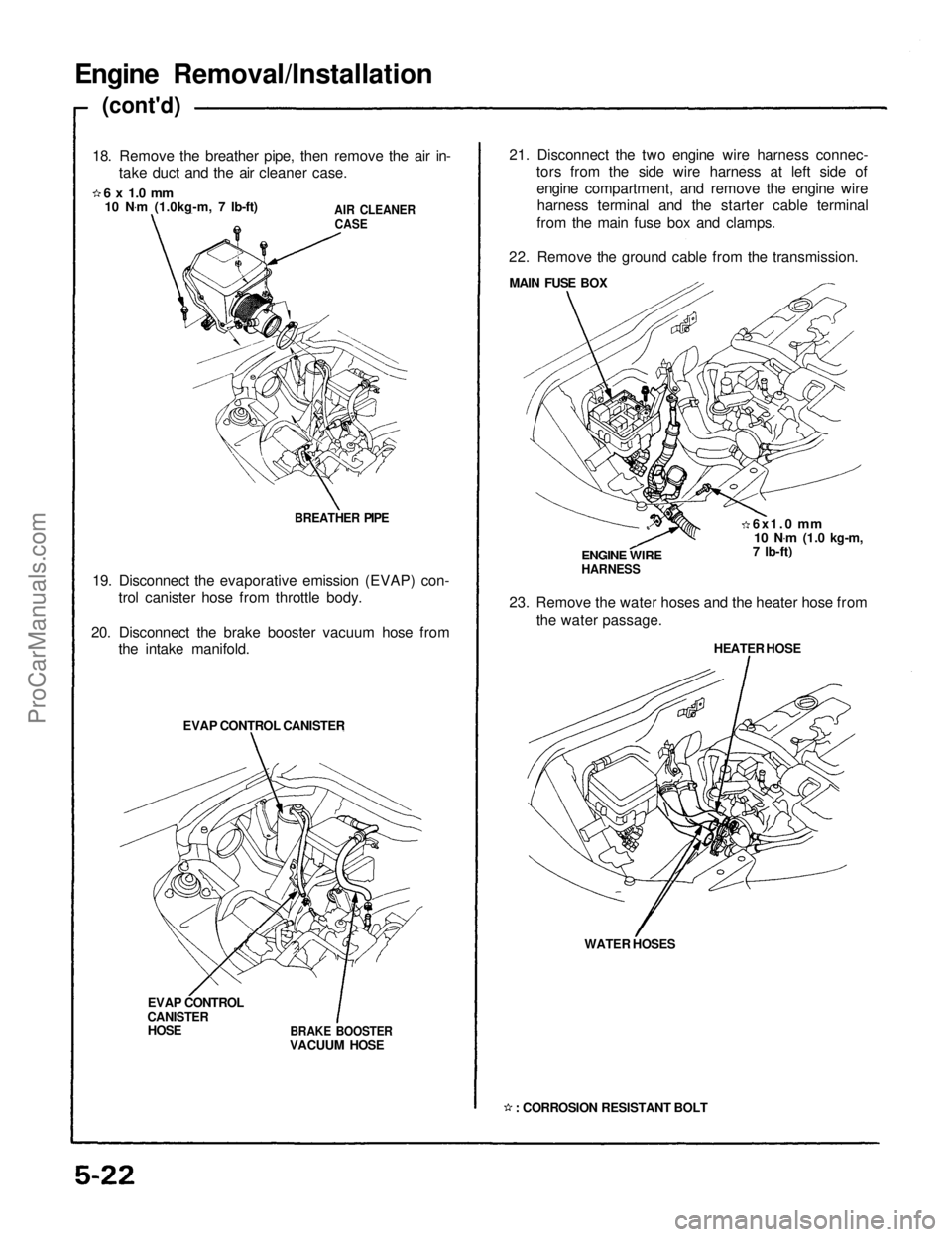
18. Remove the breather pipe, then remove the air in- take duct and the air cleaner case.
6 x 1.0 mm
10 N .
m (1.0kg-m, 7 Ib-ft)
AIR CLEANER
CASE
BREATHER PIPE
19. Disconnect the evaporative emission (EVAP) con- trol canister hose from throttle body.
20. Disconnect the brake booster vacuum hose from the intake manifold.
EVAP CONTROL CANISTER
EVAP CONTROL
CANISTER
HOSE
BRAKE BOOSTER
VACUUM HOSE 21. Disconnect the two engine wire harness connec-
tors from the side wire harness at left side of
engine compartment, and remove the engine wireharness terminal and the starter cable terminal
from the main fuse box and clamps.
22. Remove the ground cable from the transmission. MAIN FUSE BOX
6x1.0
mm
10 N .
m
(1.0 kg-m,
7 Ib-ft)
ENGINE WIRE
HARNESS
23. Remove the water hoses and the heater hose from the water passage.
HEATER HOSE
WATER HOSES
: CORROSION RESISTANT BOLTProCarManuals.com
Page 990 of 1640
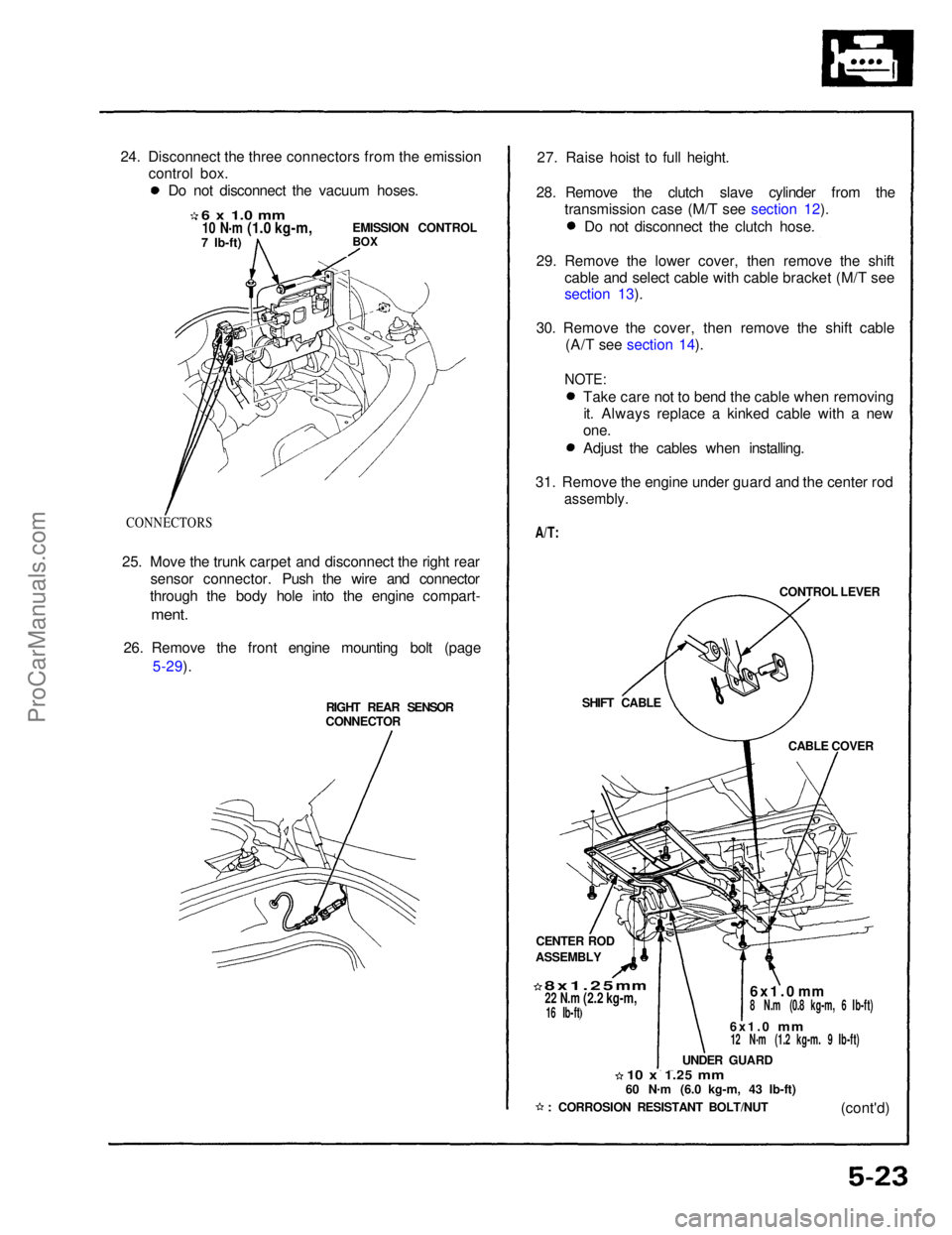
24. Disconnect the three connectors from the emission
control box.
6 x 1.0 mm
10 N .
m
(1.0 kg-m,
7 Ib-ft)
EMISSION CONTROL
BOX
CONNECTORS
25. Move the trunk carpet and disconnect the right rear sensor connector. Push the wire and connector
through the body hole into the engine compart-
ment.
26. Remove the front engine mounting bolt (page 5-29).
RIGHT REAR SENSOR
CONNECTOR 27. Raise hoist to full height.
28. Remove the clutch slave cylinder from the transmission case (M/T see section 12).
CONTROL LEVER
SHIFT CABLE CABLE COVER
CENTER ROD
ASSEMBLY
8x1.25
mm
22 N.m
(2.2 kg-m,
16 Ib-ft)
6x1.0
mm
8 N.m (0.8 kg-m, 6 Ib-ft)
6x1.0
mm
12 N
.
m (1.2 kg-m. 9 Ib-ft)
UNDER GUARD
10 x
1.25
mm
60 N
.
m (6.0 kg-m, 43 Ib-ft)
(cont'd)
: CORROSION RESISTANT BOLT/NUT
Do not disconnect the vacuum hoses.
Do not disconnect the clutch hose.
29. Remove the lower cover, then remove the shift cable and select cable with cable bracket (M/T see
section 13).
30. Remove the cover, then remove the shift cable (A/T see section 14).
NOTE:
Take care not to bend the cable when removingit. Always replace a kinked cable with a new
one.
Adjust the cables when installing.
31. Remove the engine under guard and the center rod
assembly.
A/T:ProCarManuals.com