ACURA NSX 1997 Service Repair Manual
Manufacturer: ACURA, Model Year: 1997, Model line: NSX, Model: ACURA NSX 1997Pages: 1503, PDF Size: 57.08 MB
Page 1001 of 1503
Thickness an d Parallelis m
Inspectio n
1. Rais e bot h side s o f th e vehicle , an d suppor t i t o n
safet y stand s (se e pag e 1- 10 throug h 1-12 ).
Remov e th e rea r wheels .
2 . Mov e th e calipe r an d pad s ou t o f th e wa y a s
describe d o n th e precedin g page .
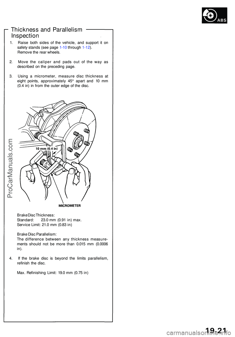
3 . Usin g a micrometer , measur e dis c thicknes s a t
eigh t points , approximatel y 45 ° apar t an d 1 0 m m
(0. 4 in ) i n fro m th e oute r edg e o f th e disc .
Brak e Dis c Thickness :
Standard : 23. 0 m m (0.9 1 in ) max .
Servic e Limit : 21. 0 m m (0.8 3 in )
Brak e Dis c Parallelism :
Th e differenc e betwee n an y thicknes s measure -
ment s shoul d no t b e mor e tha n 0.01 5 m m (0.000 6
in).
4. I f th e brak e dis c i s beyon d th e limit s parallelism ,
refinis h th e disc .
Max . Refinishin g Limit : 19. 0 m m (0.7 5 in )
ProCarManuals.com
Page 1002 of 1503
Rear Calipe r
Disassembl y
• Neve r us e a n ai r hos e o r dr y brus h t o clea n brak e
assemblies .
• Us e a n OSHA-approve d vacuu m cleane r t o avoi d
breathin g brak e dust .
CAUTION :
• D o no t spil l brak e flui d o n th e vehicle ; i t ma y damag e
th e paint ; i f brak e flui d doe s contac t th e paint , was h
it of f immediatel y wit h water .
• T o preven t spills , cove r th e hos e joint s wit h rag s o r
sho p towels .
• Clea n al l part s i n brak e flui d an d ai r dry ; blo w ou t al l
passage s wit h compresse d air .
1 . Remov e th e calipe r shiel d (se e pag e 19-18 ).
2 . Disconnec t th e parkin g cabl e (se e pag e 19-18 ).
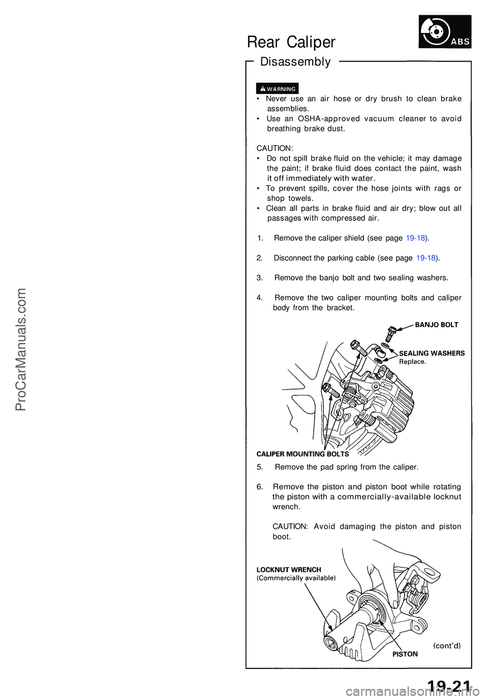
3 . Remov e th e banj o bol t an d tw o sealin g washers .
4 . Remov e th e tw o calipe r mountin g bolt s an d calipe r
bod y fro m th e bracket .
5 . Remov e th e pa d sprin g fro m th e caliper .
6. Remov e th e pisto n an d pisto n boo t whil e rotatin g
the pisto n wit h a commercially-availabl e locknu t
wrench.
CAUTION : Avoi d damagin g th e pisto n an d pisto n
boot .
ProCarManuals.com
Page 1003 of 1503
Disassembly (cont'd )
Rear Calipe r
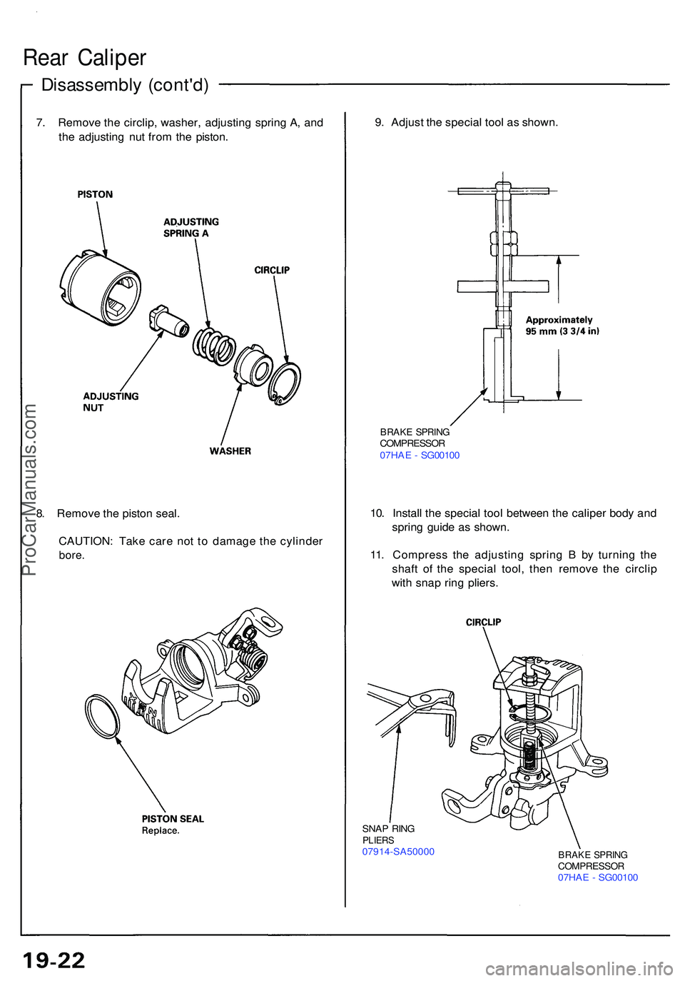
7. Remov e th e circlip , washer , adjustin g sprin g A , an d
th e adjustin g nu t fro m th e piston . 9
. Adjus t th e specia l too l a s shown .
BRAKE SPRIN GCOMPRESSO R
07HA E - SG0010 0
10. Instal l th e specia l too l betwee n th e calipe r bod y an d
sprin g guid e a s shown .
11 . Compres s th e adjustin g sprin g B by turnin g th e
shaf t o f th e specia l tool , the n remov e th e circli p
wit h sna p rin g pliers .
8
. Remov e th e pisto n seal .
CAUTION : Tak e car e no t t o damag e th e cylinde r
bore.
SNAP RIN GPLIER S07914-SA5000 0BRAKE SPRIN GCOMPRESSO R07HAE - SG0010 0
ProCarManuals.com
Page 1004 of 1503
12. Remove the adjusting bolt.
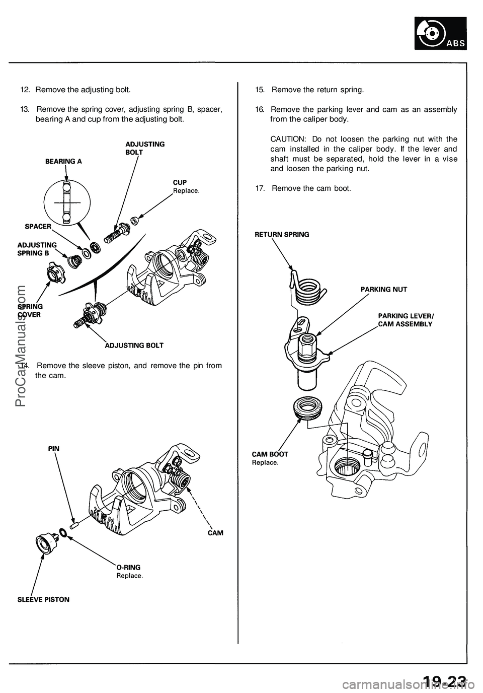
13. Remove the spring cover, adjusting spring B, spacer,
bearing A and cup from the adjusting bolt.
15. Remove the return spring.
16. Remove the parking lever and cam as an assembly
from the caliper body.
CAUTION: Do not loosen the parking nut with the
cam installed in the caliper body. If the lever and
shaft must be separated, hold the lever in a vise
and loosen the parking nut.
17. Remove the cam boot.
14. Remove the sleeve piston, and remove the pin from
the
cam.ProCarManuals.com
Page 1005 of 1503
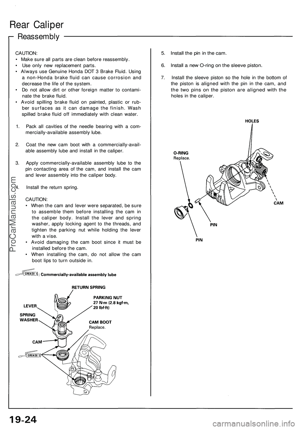
Reassembly
Rear Calipe r
CAUTION :
• Mak e sur e al l part s ar e clea n befor e reassembly .
• Us e onl y ne w replacemen t parts .
• Alway s us e Genuin e Hond a DO T 3 Brak e Fluid . Usin g
a non-Hond a brak e flui d ca n caus e corrosio n an d
decreas e th e lif e o f th e system .
• D o no t allo w dir t o r othe r foreig n matte r t o contami -
nat e th e brak e fluid .
• Avoi d spillin g brak e flui d o n painted , plasti c o r rub -
be r surface s a s i t ca n damag e th e finish . Was h
spille d brak e flui d of f immediatel y wit h clea n water .
1 . Pac k al l cavitie s o f th e needl e bearin g wit h a com -
mercially-availabl e assembl y lube .
2 . Coa t th e ne w ca m boo t wit h a commercially-avail -
abl e assembl y lub e an d instal l i n th e caliper .
3 . Appl y commercially-availabl e assembl y lub e t o th e
pi n contactin g are a o f th e cam , an d instal l th e ca m
an d leve r assembl y int o th e calipe r body .
4 . Instal l th e retur n spring .
CAUTION :
• Whe n th e ca m an d leve r wer e separated , b e sur e
t o assembl e the m befor e installin g th e ca m in
th e calipe r body . Instal l th e leve r an d sprin g
washer , appl y lockin g agen t t o th e threads , an d
tighte n th e parkin g nu t whil e holdin g th e leve r
wit h a vise .
• Avoi d damagin g th e ca m boo t sinc e i t mus t b e
installe d befor e th e cam .
• Whe n installin g th e cam , d o no t allo w th e ca m
boo t lip s t o tur n outsid e in .5. Instal l th e pi n in th e cam .
6. Instal l a ne w O-rin g o n th e sleev e piston .
7. Instal l th e sleev e pisto n s o th e hol e i n th e botto m o f
the pisto n i s aligne d wit h th e pi n i n th e cam , an d
the tw o pin s o n th e pisto n ar e aligne d wit h th e
hole s i n th e caliper .
ProCarManuals.com
Page 1006 of 1503
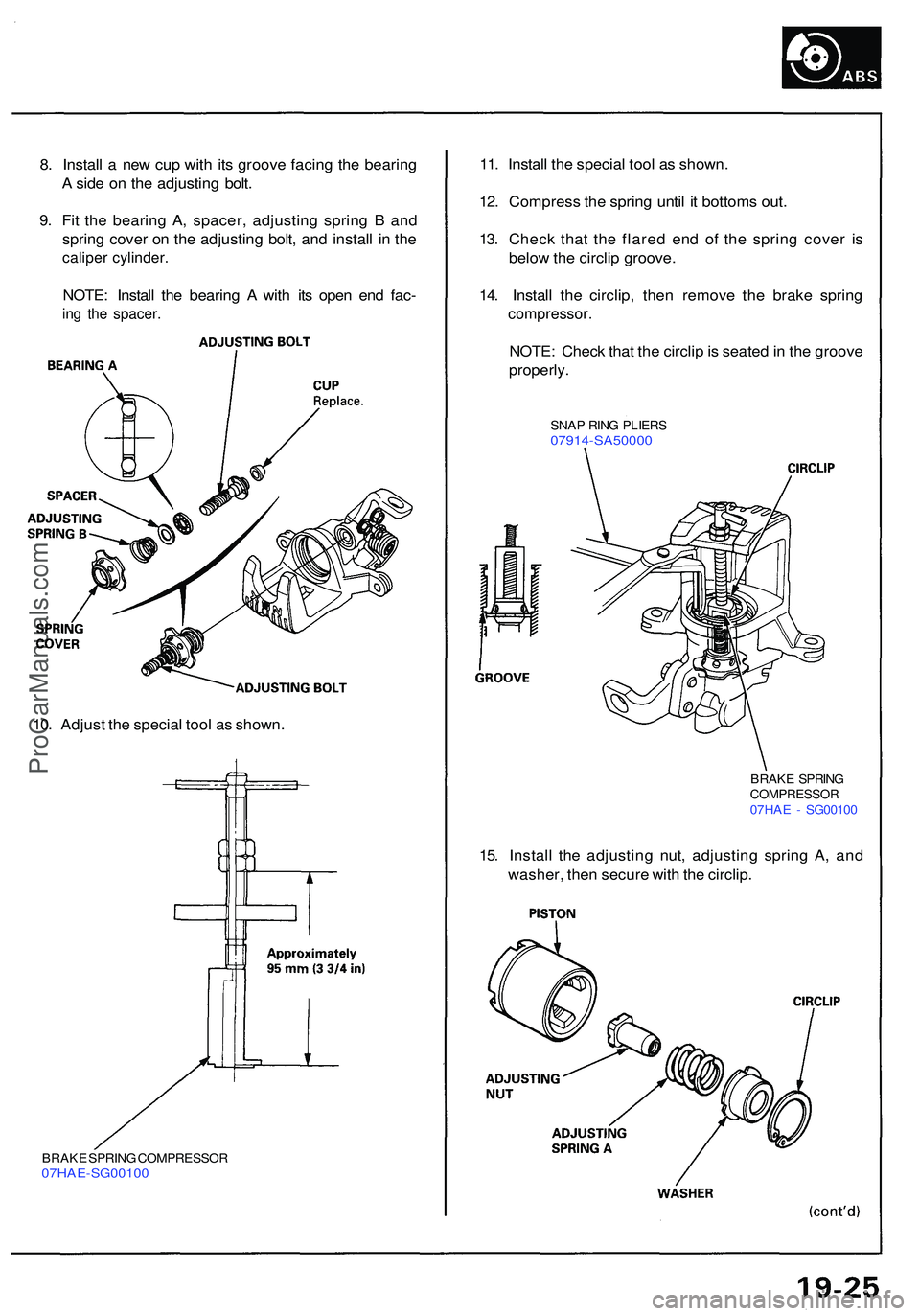
8. Instal l a ne w cu p wit h it s groov e facin g th e bearin g
A sid e o n th e adjustin g bolt .
9 . Fi t th e bearin g A , spacer , adjustin g sprin g B an d
sprin g cove r o n th e adjustin g bolt , an d instal l i n th e
calipe r cylinder .
NOTE: Instal l th e bearin g A wit h it s ope n en d fac -
ing th e spacer .
11. Instal l th e specia l too l a s shown .
12 . Compres s th e sprin g unti l i t bottom s out .
13 . Chec k tha t th e flare d en d o f th e sprin g cove r i s
belo w th e circli p groove .
14 . Instal l th e circlip , the n remov e th e brak e sprin g
compressor .
NOTE: Chec k tha t th e circli p is seate d in th e groov e
properly .
SNAP RIN G PLIER S07914-SA5000 0
BRAKE SPRIN GCOMPRESSO R07HAE - SG0010 0
15. Instal l th e adjustin g nut , adjustin g sprin g A , an d
washer , the n secur e wit h th e circlip .
10
. Adjus t th e specia l too l a s shown .
BRAKE SPRIN G COMPRESSO R07HAE-SG0010 0
ProCarManuals.com
Page 1007 of 1503
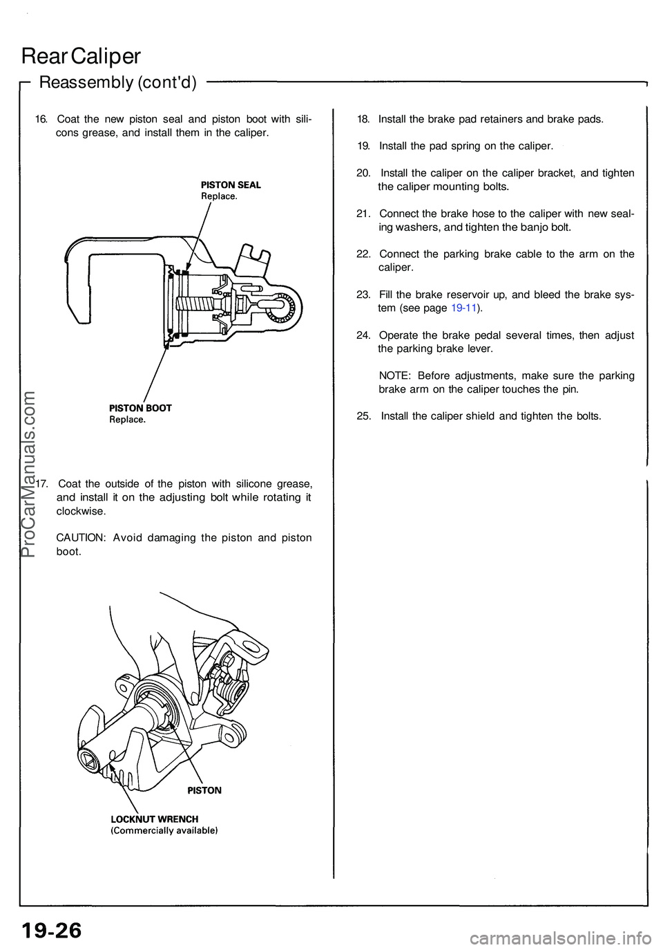
Reassembly (cont'd )
Rear Calipe r
16. Coa t th e ne w pisto n sea l an d pisto n boo t wit h sili -
con s grease , an d instal l the m in th e caliper . 18
. Instal l th e brak e pa d retainer s an d brak e pads .
19 . Instal l th e pa d sprin g o n th e caliper .
20 . Instal l th e calipe r o n th e calipe r bracket , an d tighte n
the calipe r mountin g bolts .
21. Connec t th e brak e hos e t o th e calipe r wit h ne w seal -
ing washers , an d tighte n th e banj o bolt .
22. Connec t th e parkin g brak e cabl e t o th e ar m o n th e
caliper .
23 . Fil l th e brak e reservoi r up , an d blee d th e brak e sys -
te m (se e pag e 19-11 ).
24 . Operat e th e brak e peda l severa l times , the n adjus t
th e parkin g brak e lever .
NOTE : Befor e adjustments , mak e sur e th e parkin g
brak e ar m o n th e calipe r touche s th e pin .
25 . Instal l th e calipe r shiel d an d tighte n th e bolts .
17 . Coa t th e outsid e o f th e pisto n wit h silicon e grease ,
and instal l i t o n th e adjustin g bol t whil e rotatin g i t
clockwise .
CAUTION : Avoi d damagin g th e pisto n an d pisto n
boot .
ProCarManuals.com
Page 1008 of 1503
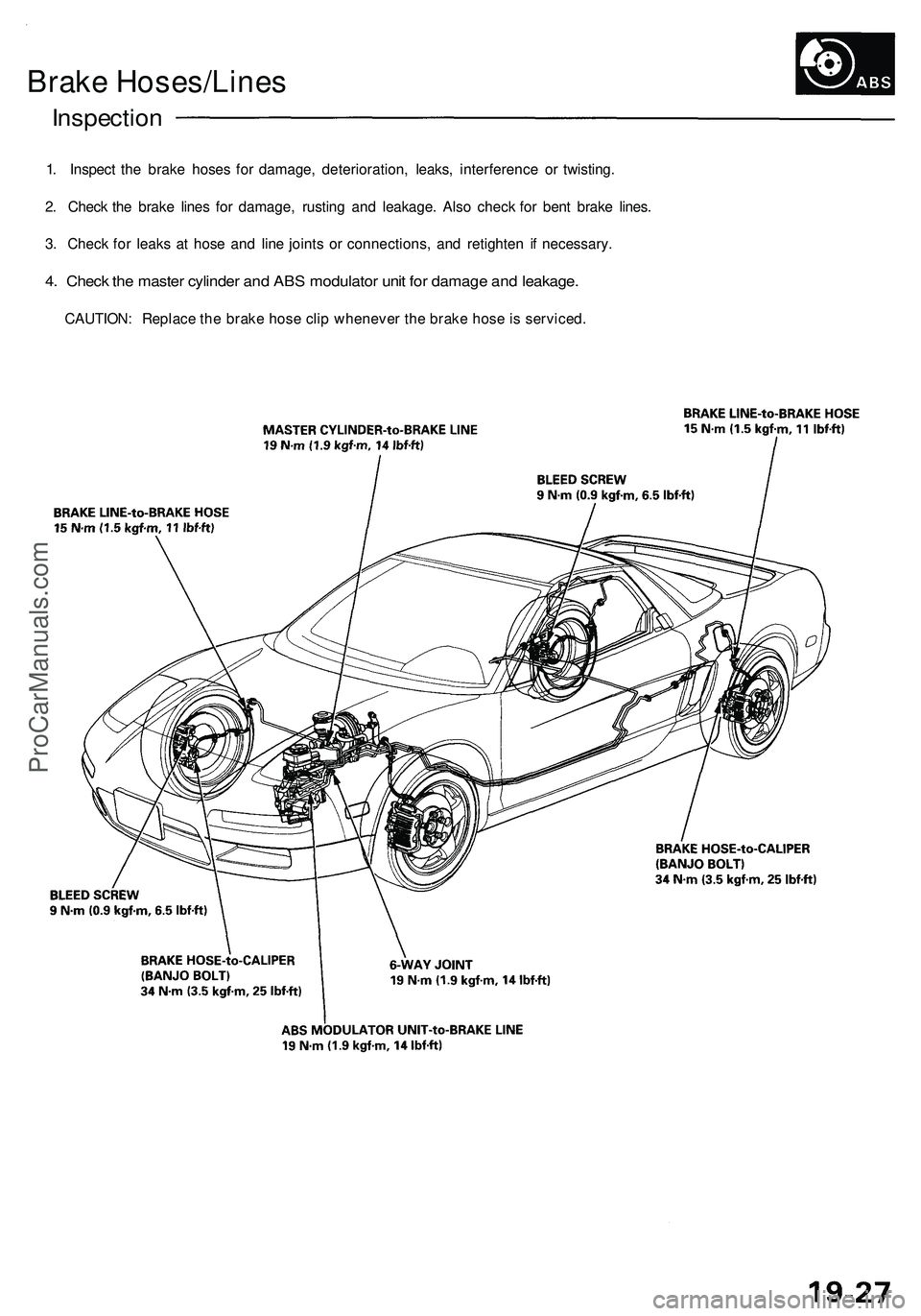
Brake Hoses/Lines
Inspection
1. Inspect the brake hoses for damage, deterioration, leaks, interference or twisting.
2. Check the brake lines for damage, rusting and leakage. Also check for bent brake lines.
3. Check for leaks at hose and line joints or connections, and retighten if necessary.
4. Check the master cylinder and ABS modulator unit for damage and leakage.
CAUTION: Replace the brake hose clip whenever the brake hose is serviced.ProCarManuals.com
Page 1009 of 1503
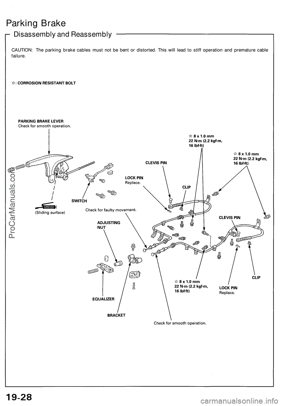
Disassembly and Reassembly
Parking Brake
CAUTION: The parking brake cables must not be bent or distorted. This will lead to stiff operation and premature cable
failure.ProCarManuals.com
Page 1010 of 1503
Features/Construction/Operation
Anti-lock Brake System (ABS) Description
General
In a conventional brake system, if the brake pedal is depressed excessively, the wheels can lock before the vehicle comes
to a stop. In such a case, the stability of the vehicle is reduced if the rear wheels are locked, and maneuverability of the
vehicle is reduced if the front wheels are locked, creating an extremely unstable condition.
The Anti-lock Brake System (ABS) modulates the pressure of the brake fluid applied to each caliper, thereby preventing
the locking of the wheels, whenever the wheels are likely to locked due to be excessive braking. It then restores normal
hydraulic pressure when there is no longer any possibility of wheel locking.
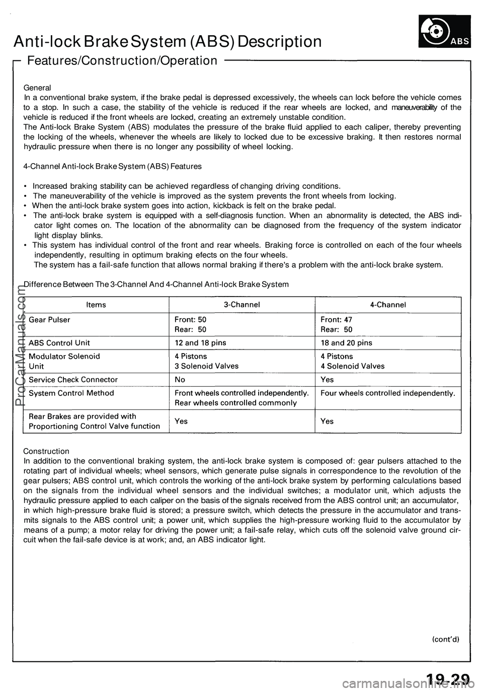
4-Channel Anti-lock Brake System (ABS) Features
• Increased braking stability can be achieved regardless of changing driving conditions.
• The maneuverability of the vehicle is improved as the system prevents the front wheels from locking.
• When the anti-lock brake system goes into action, kickback is felt on the brake pedal.
• The anti-lock brake system is equipped with a self-diagnosis function. When an abnormality is detected, the ABS indi-
cator light comes on. The location of the abnormality can be diagnosed from the frequency of the system indicator
light display blinks.
• This system has individual control of the front and rear wheels. Braking force is controlled on each of the four wheels
independently, resulting in optimum braking efects on the four wheels.
The system has a fail-safe function that allows normal braking if there's a problem with the anti-lock brake system.
Difference Between The 3-Channel And 4-Channel Anti-lock Brake System
Construction
In addition to the conventional braking system, the anti-lock brake system is composed of: gear pulsers attached to the
rotating part of individual wheels; wheel sensors, which generate pulse signals in correspondence to the revolution of the
gear pulsers; ABS control unit, which controls the working of the anti-lock brake system by performing calculations based
on the signals from the individual wheel sensors and the individual switches; a modulator unit, which adjusts the
hydraulic pressure applied to each caliper on the basis of the signals received from the ABS control unit; an accumulator,
in which high-pressure brake fluid is stored; a pressure switch, which detects the pressure in the accumulator and trans-
mits signals to the ABS control unit; a power unit, which supplies the high-pressure working fluid to the accumulator by
means of a pump; a motor relay for driving the power unit; a fail-safe relay, which cuts off the solenoid valve ground cir-
cuit when the fail-safe device is at work; and, an ABS indicator light.ProCarManuals.com