ACURA NSX 1997 Service Repair Manual
Manufacturer: ACURA, Model Year: 1997, Model line: NSX, Model: ACURA NSX 1997Pages: 1503, PDF Size: 57.08 MB
Page 991 of 1503
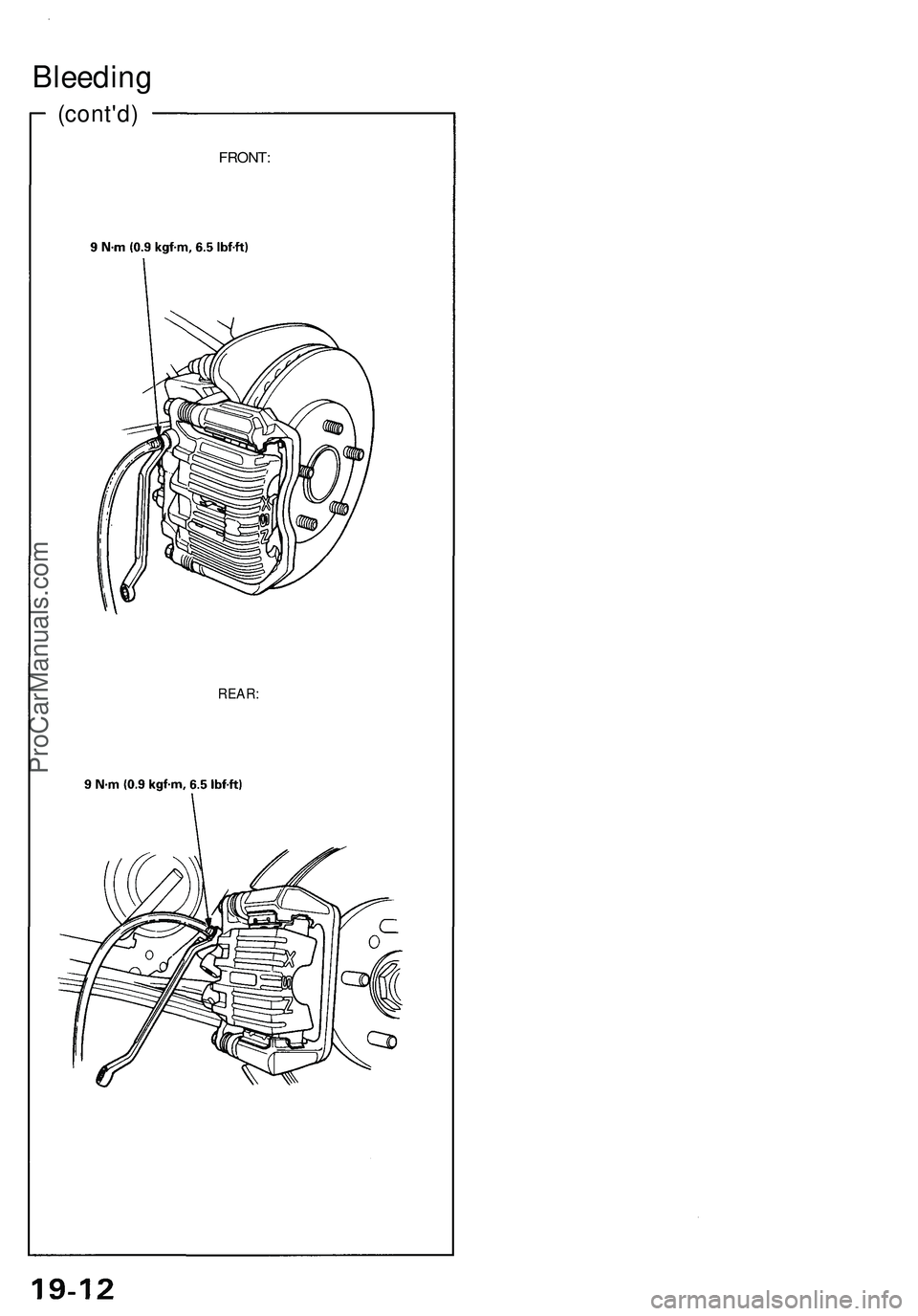
(cont'd)
FRONT:
Bleeding
REAR:ProCarManuals.com
Page 992 of 1503
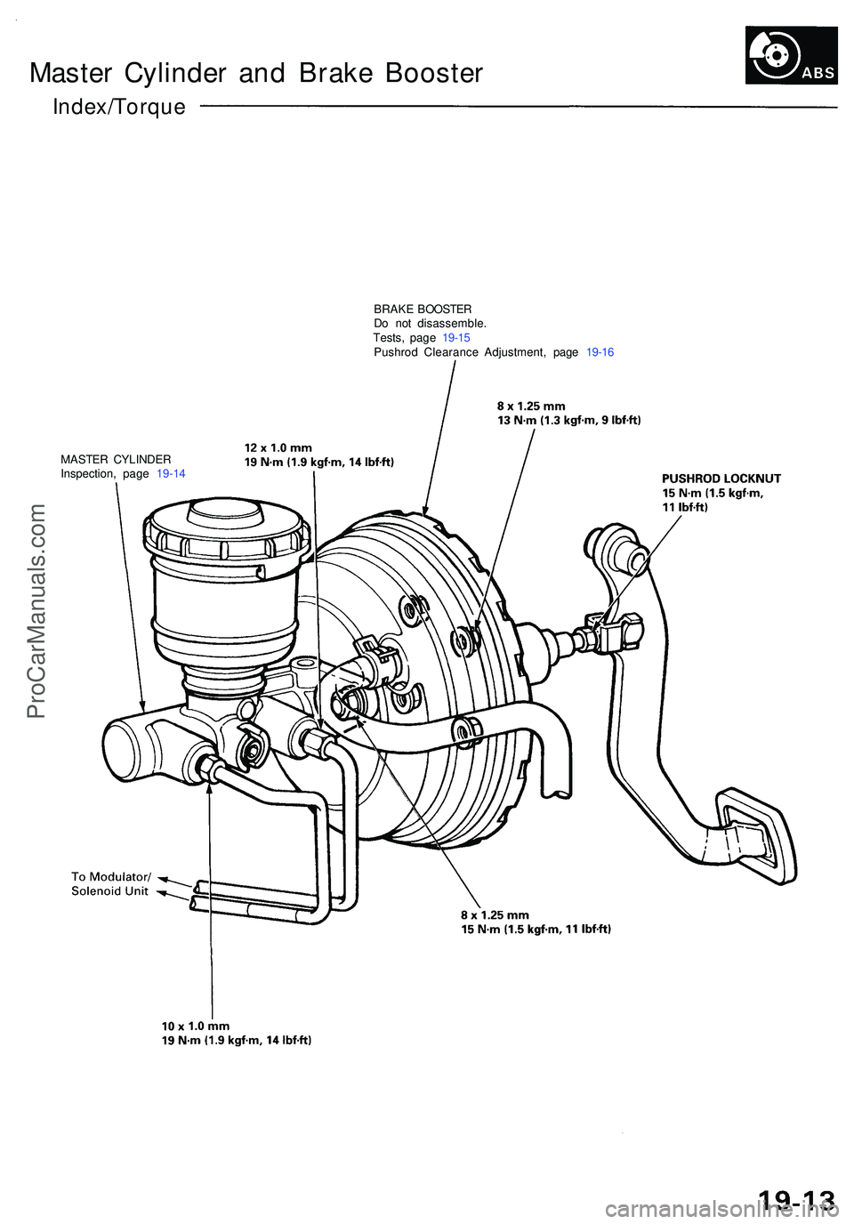
Master Cylinde r an d Brak e Booste r
Index/Torqu e
BRAKE BOOSTE R
D o no t disassemble .
Tests , pag e 19-1 5
Pushro d Clearanc e Adjustment , pag e 19-1 6
MASTE R CYLINDE R
Inspection , pag e 19-1 4
ProCarManuals.com
Page 993 of 1503
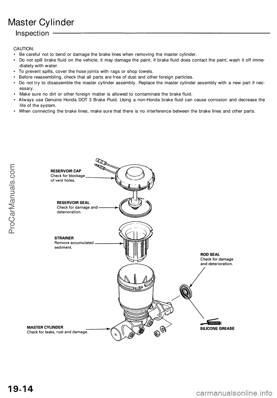
Master Cylinder
Inspection
CAUTION:
• Be careful not to bend or damage the brake lines when removing the master cylinder.
• Do not spill brake fluid on the vehicle; it may damage the paint; if brake fluid does contact the paint, wash it off imme-
diately with water.
• To prevent spills, cover the hose joints with rags or shop towels.
• Before reassembling, check that all parts are free of dust and other foreign particles.
• Do not try to disassemble the master cylinder assembly. Replace the master cylinder assembly with a new part if nec-
essary.
• Make sure no dirt or other foreign matter is allowed to contaminate the brake fluid.
• Always use Genuine Honda DOT 3 Brake Fluid. Using a non-Honda brake fluid can cause corrosion and decrease the
life of the system.
• When connecting the brake lines, make sure that there is no interference between the brake lines and other parts.ProCarManuals.com
Page 994 of 1503
Tests
Brake Booster
Functional Test
1. With the engine stopped, depress the brake pedal
several times to deplete the vacuum reservoir, then
depress the pedal hard and hold it for 15 seconds. If
the pedal sinks, either the master cylinder is
bypassing internally, or the brake system (master
cylinder, lines, modulator, proportioning valve, or
calipers) is leaking.
2. Start the engine with the pedal depressed. If the
pedal sinks slightly, the vacuum booster is operat-
ing normally, if the pedal height does not vary, the
booster or check valve is faulty.
3. With the engine running, depress the brake pedal
lightly. Apply just enough pressure to hold back
automatic transmission creep. If the brake pedal
sinks more than 10 mm (3/8 in.) in three minutes,
the master cylinder is faulty. A slight change in
pedal height when the A/C compressor cycles on
and off if normal. (The A/C compressor load
changes the vacuum available to the booster.)
Leak Test
1. Depress the brake pedal with the engine running,
then stop the engine. If the pedal height does not
vary while depressed for 30 seconds, the vacuum
booster is OK. If the pedal rises, the booster is
faulty.
2. With the engine stopped, depress the brake pedal
several times using normal pressure. When the
pedal is first depressed, it should be low. On con-
secutive applications, the pedal height should grad-
ually rise. If the pedal position does not vary, check
the booster check valve.
Booster Check Valve Test
1. Disconnect the brake booster vacuum hose at the
booster or at the booster side of the valve.
2. Start the engine and let it idle. There should be vac-
uum. If no vacuum is available, the check valve is
not working properly. Replace the check valve and
retest.ProCarManuals.com
Page 995 of 1503
Pushrod Clearanc e Adjustmen t
Brake Booste r
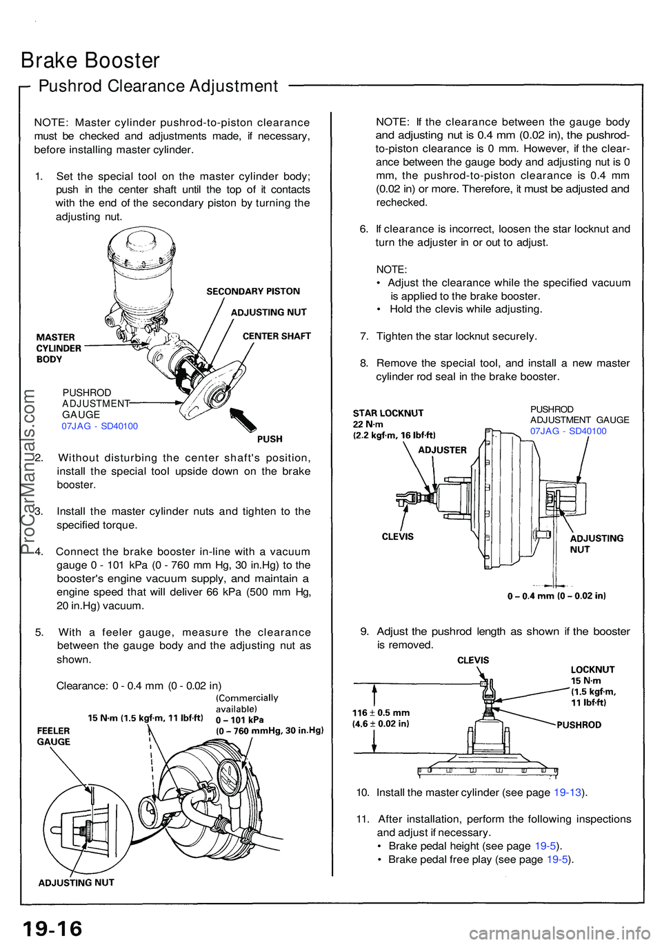
NOTE: Maste r cylinde r pushrod-to-pisto n clearanc e
mus t b e checke d an d adjustment s made , i f necessary ,
befor e installin g maste r cylinder .
1 . Se t th e specia l too l o n th e maste r cylinde r body ;
pus h i n th e cente r shaf t unti l th e to p o f i t contact s
wit h th e en d o f th e secondar y pisto n b y turnin g th e
adjustin g nut . NOTE
: I f th e clearanc e betwee n th e gaug e bod y
and adjustin g nu t i s 0. 4 m m (0.0 2 in) , th e pushrod -
to-piston clearanc e i s 0 mm . However , i f th e clear -
anc e betwee n th e gaug e bod y an d adjustin g nu t i s 0
mm , th e pushrod-to-pisto n clearanc e i s 0. 4 m m
(0.0 2 in ) o r more . Therefore , i t mus t b e adjuste d an d
rechecked .
6. I f clearanc e i s incorrect , loose n th e sta r locknu t an d
tur n th e adjuste r i n o r ou t t o adjust .
NOTE:
• Adjus t th e clearanc e whil e th e specifie d vacuu m
i s applie d to th e brak e booster .
• Hol d th e clevi s whil e adjusting .
7 . Tighte n th e sta r locknu t securely .
8 . Remov e th e specia l tool , an d instal l a ne w maste r
cylinde r ro d sea l i n th e brak e booster.
PUSHRO D
ADJUSTMEN T GAUG E
07JA G - SD4010 0
PUSHRODADJUSTMEN TGAUGE07JAG - SD4010 0
2. Withou t disturbin g th e cente r shaft' s position ,
instal l th e specia l too l upsid e dow n o n th e brak e
booster .
3. Instal l th e maste r cylinde r nut s an d tighte n t o th e
specifie d torque .
4 . Connec t th e brak e booste r in-lin e wit h a vacuu m
gaug e 0 - 10 1 kP a ( 0 - 76 0 m m Hg , 3 0 in.Hg ) t o th e
booster' s engin e vacuu m supply , an d maintai n a
engin e spee d tha t wil l delive r 6 6 kP a (50 0 m m Hg ,
2 0 in.Hg ) vacuum .
5 . Wit h a feele r gauge , measur e th e clearanc e
betwee n th e gaug e bod y an d th e adjustin g nu t a s
shown .
Clearance : 0 - 0. 4 m m (0 - 0.0 2 in )
9. Adjus t th e pushro d lengt h a s show n i f th e booste r
is removed .
10 . Instal l th e maste r cylinde r (se e pag e 19-13 ).
11 . Afte r installation , perfor m th e followin g inspection s
an d adjus t i f necessary .
• Brak e peda l heigh t (se e pag e 19-5 ).
• Brak e peda l fre e pla y (se e pag e 19-5 ).
ProCarManuals.com
Page 996 of 1503
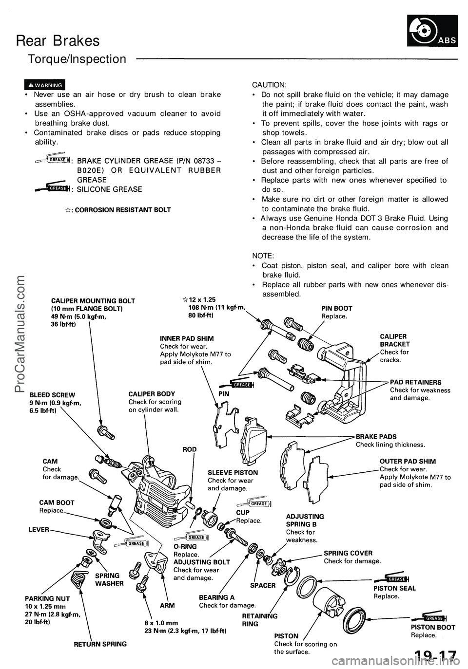
Rear Brakes
Torque/Inspection
• Never use an air hose or dry brush to clean brake
assemblies.
• Use an OSHA-approved vacuum cleaner to avoid
breathing brake dust.
• Contaminated brake discs or pads reduce stopping
ability.
CAUTION:
• Do not spill brake fluid on the vehicle; it may damage
the paint; if brake fluid does contact the paint, wash
it off immediately with water.
• To prevent spills, cover the hose joints with rags or
shop towels.
• Clean all parts in brake fluid and air dry; blow out all
passages with compressed air.
• Before reassembling, check that all parts are free of
dust and other foreign particles.
• Replace parts with new ones whenever specified to
do so.
• Make sure no dirt or other foreign matter is allowed
to contaminate the brake fluid.
• Always use Genuine Honda DOT 3 Brake Fluid. Using
a non-Honda brake fluid can cause corrosion and
decrease the life of the system.
NOTE:
• Coat piston, piston seal, and caliper bore with clean
brake fluid.
• Replace all rubber parts with new ones whenever dis-
assembled.ProCarManuals.com
Page 997 of 1503
Rear Brak e Pad s
Inspection/Replacemen t
• Neve r us e a n ai r hos e o r dr y brus h t o clea n brak e
assemblies .
• Us e a n OSHA-approve d vacuu m cleane r t o avoi d
breathin g brak e dust .
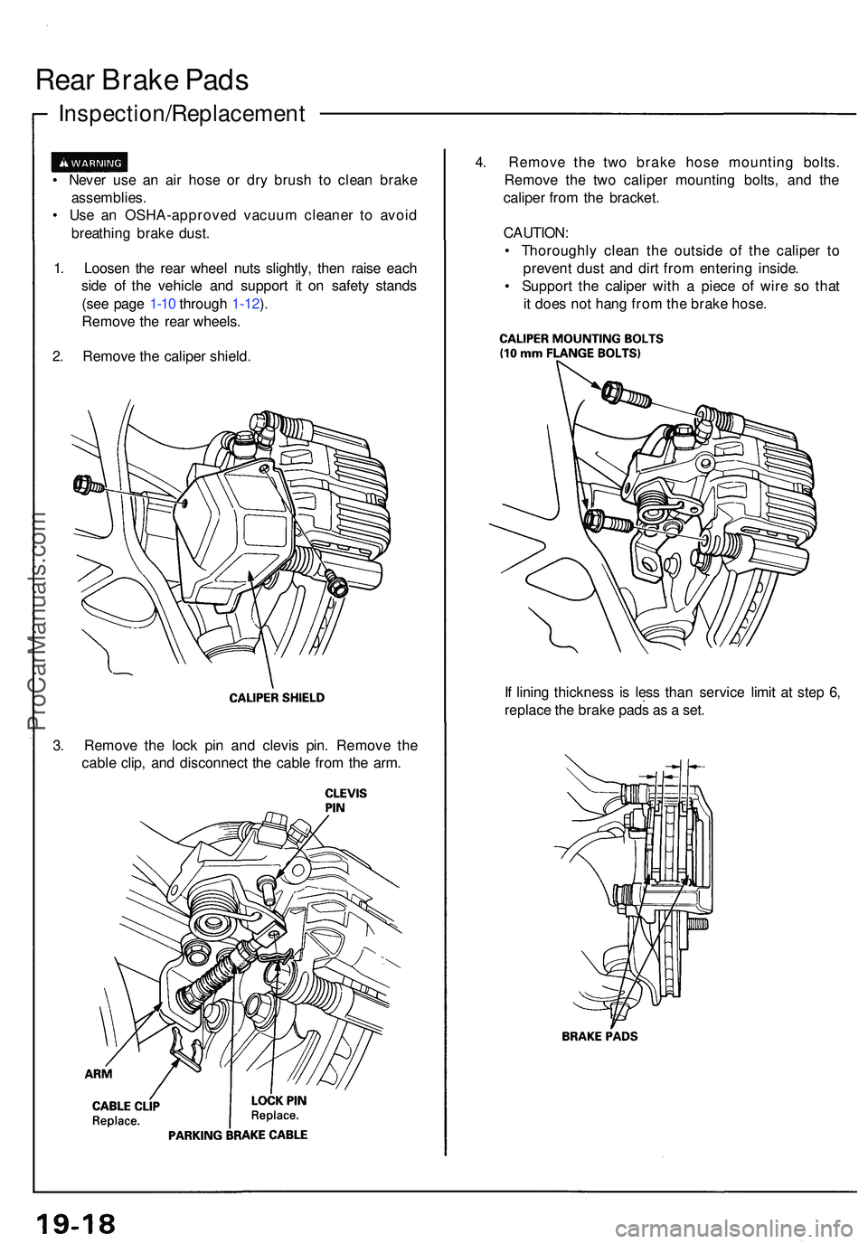
1 . Loose n th e rea r whee l nut s slightly , the n rais e eac h
sid e o f th e vehicl e an d suppor t i t o n safet y stand s
(se e pag e 1-10 throug h 1-12 ).
Remov e th e rea r wheels .
2 . Remov e th e calipe r shield . 4
. Remov e th e tw o brak e hos e mountin g bolts .
Remov e th e tw o calipe r mountin g bolts , an d th e
calipe r fro m th e bracket .
CAUTION :
• Thoroughl y clea n th e outsid e o f th e calipe r t o
preven t dus t an d dir t fro m enterin g inside .
• Suppor t th e calipe r wit h a piec e o f wir e s o tha t
i t doe s no t han g fro m th e brak e hose .
I f linin g thicknes s i s les s tha n servic e limi t a t ste p 6 ,
replac e th e brak e pad s a s a set .
3 . Remov e th e loc k pi n an d clevi s pin . Remov e th e
cabl e clip , an d disconnec t th e cabl e fro m th e arm .
ProCarManuals.com
Page 998 of 1503
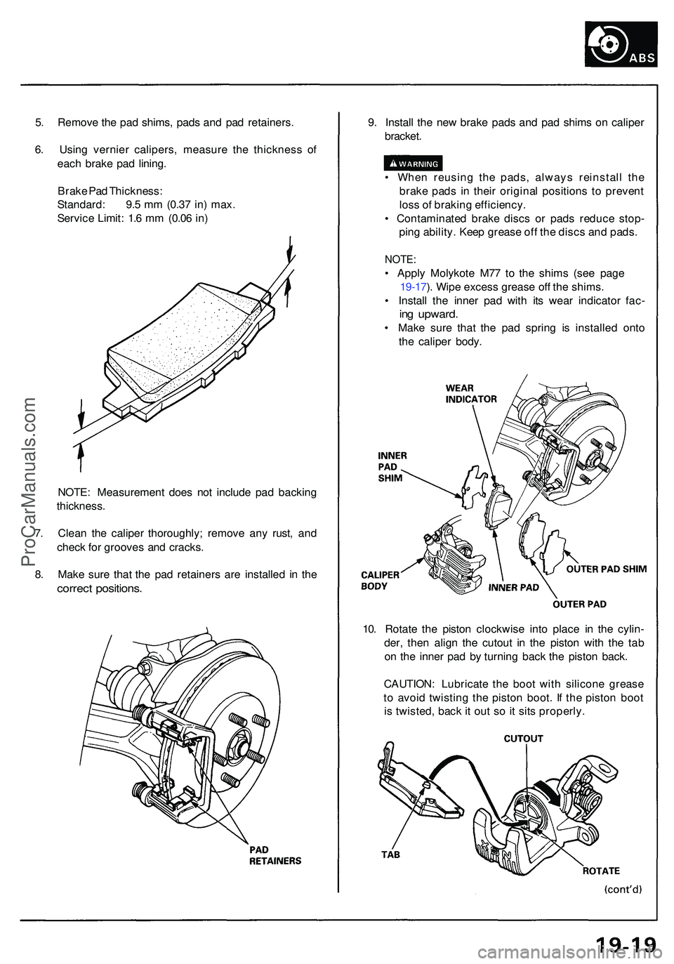
5. Remov e th e pa d shims , pad s an d pa d retainers .
6 . Usin g vernie r calipers , measur e th e thicknes s o f
eac h brak e pa d lining .
Brak e Pa d Thickness :
Standard : 9. 5 m m (0.3 7 in ) max .
Servic e Limit : 1. 6 m m (0.0 6 in ) 9
. Instal l th e ne w brak e pad s an d pa d shim s o n calipe r
bracket .
• Whe n reusin g th e pads , alway s reinstal l th e
brak e pad s i n thei r origina l position s t o preven t
los s o f brakin g efficiency .
• Contaminate d brak e disc s o r pad s reduc e stop -
pin g ability . Kee p greas e of f th e disc s an d pads .
NOTE :
• Appl y Molykote M77 t o th e shim s (se e pag e
19-17 ). Wip e exces s greas e of f th e shims .
• Instal l th e inne r pa d wit h it s wea r indicato r fac -
ing upward .
• Mak e sur e tha t th e pa d sprin g i s installe d ont o
th e calipe r body .
NOTE : Measuremen t doe s no t includ e pa d backin g
thickness .
7 . Clea n th e calipe r thoroughly ; remov e an y rust , an d
chec k fo r groove s an d cracks .
8 . Mak e sur e tha t th e pa d retainer s ar e installe d i n th e
correc t positions .
10. Rotat e th e pisto n clockwis e int o plac e i n th e cylin -
der , the n alig n th e cutou t i n th e pisto n wit h th e ta b
o n th e inne r pa d b y turnin g bac k th e pisto n back .
CAUTION : Lubricat e th e boo t wit h silicon e greas e
t o avoi d twistin g th e pisto n boot . I f th e pisto n boo t
i s twisted , bac k it ou t s o it sit s properly .
ProCarManuals.com
Page 999 of 1503
Inspection/Replacement (cont'd)
Rear Brake Pads
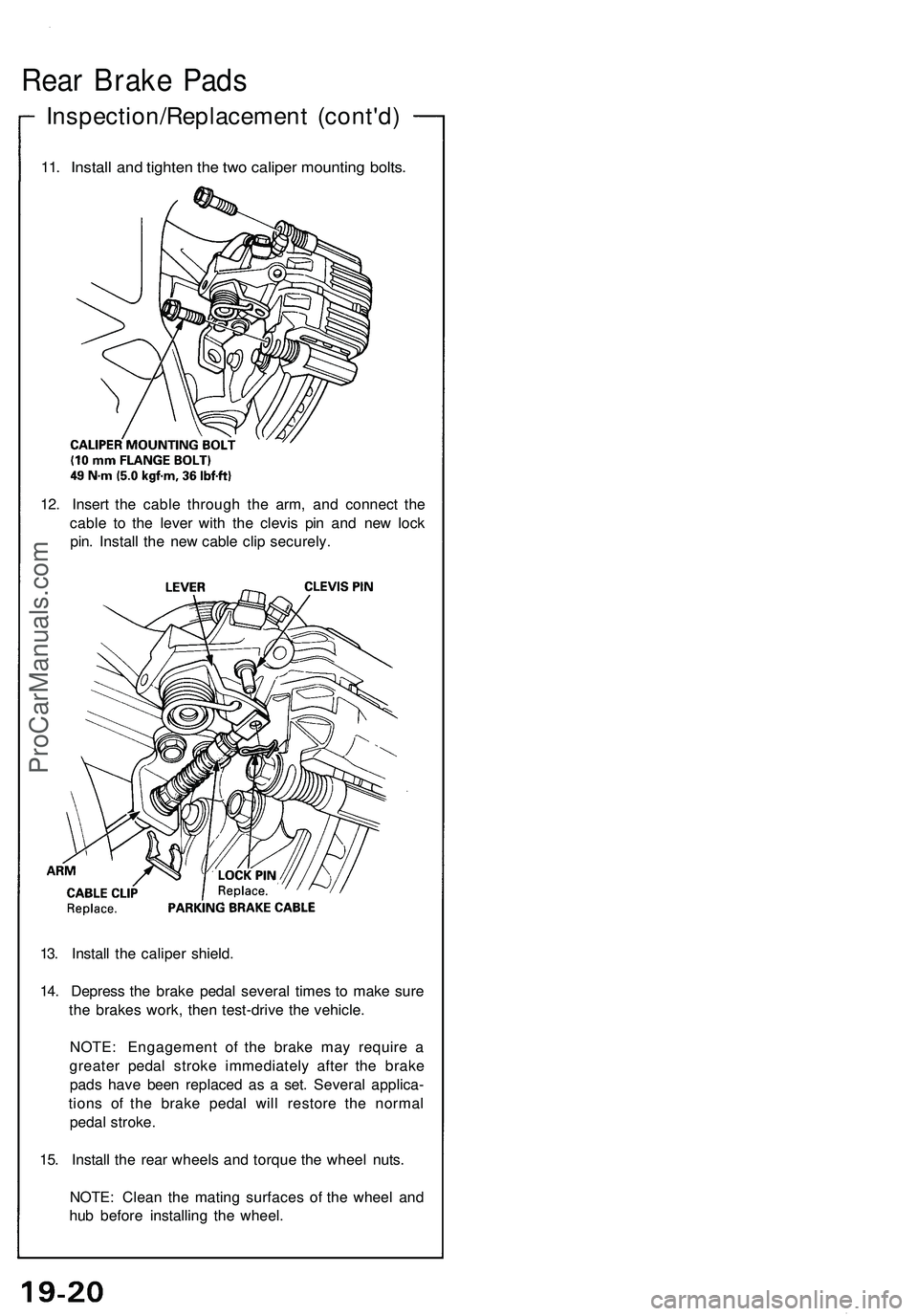
11. Install and tighten the two caliper mounting bolts.
12. Insert the cable through the arm, and connect the
cable to the lever with the clevis pin and new lock
pin. Install the new cable clip securely.
13. Install the caliper shield.
14. Depress the brake pedal several times to make sure
the brakes work, then test-drive the vehicle.
NOTE: Engagement of the brake may require a
greater pedal stroke immediately after the brake
pads have been replaced as a set. Several applica-
tions of the brake pedal will restore the normal
pedal stroke.
15. Install the rear wheels and torque the wheel nuts.
NOTE: Clean the mating surfaces of the wheel and
hub before installing the wheel.ProCarManuals.com
Page 1000 of 1503
Rear Brak e Dis c
Run-Ou t Inspectio n
1. Rais e eac h sid e o f th e vehicle , an d suppor t i t o n
safet y stand s (se e pag e 1-10 throug h 1-12 ). Remov e th e
rea r wheels .
2 . Remov e th e brak e pad s (se e pag e 19-18 ).
3 . Inspec t th e dis c surfac e fo r grooves , cracks , an d
rust . Clea n th e dis c thoroughl y an d remov e al l rust .
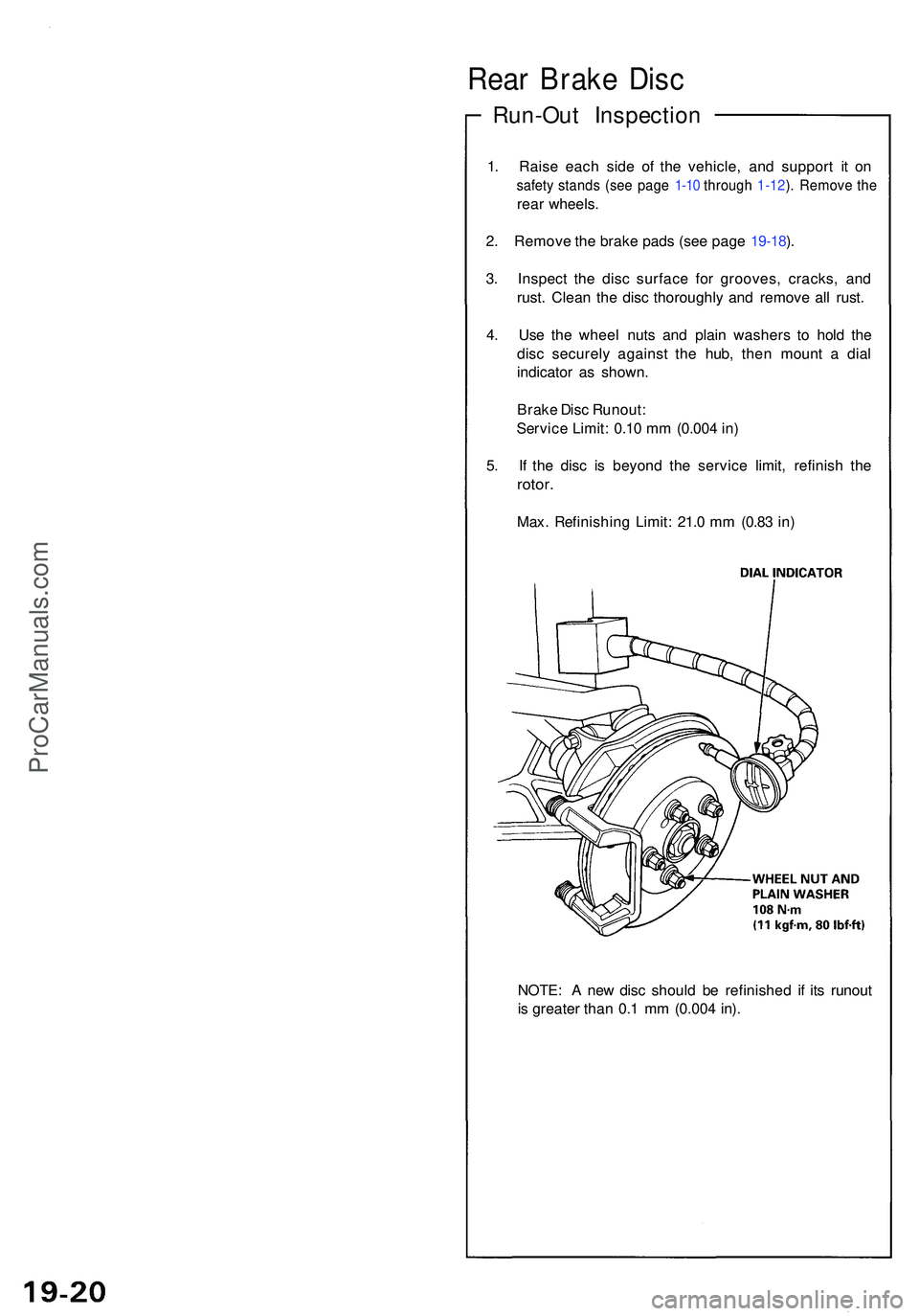
4 . Us e th e whee l nuts and plai n washer s t o hol d th e
dis c securel y agains t th e hub , the n moun t a dia l
indicato r a s shown .
Brak e Dis c Runout :
Servic e Limit : 0.1 0 m m (0.00 4 in )
5 . I f th e dis c i s beyon d th e servic e limit , refinis h th e
rotor .
Max. Refinishin g Limit : 21. 0 m m (0.8 3 in )
NOTE : A ne w dis c shoul d b e refinishe d i f it s runou t
i s greate r tha n 0. 1 m m (0.00 4 in) .
ProCarManuals.com