ACURA NSX 1997 Service Repair Manual
Manufacturer: ACURA, Model Year: 1997, Model line: NSX, Model: ACURA NSX 1997Pages: 1503, PDF Size: 57.08 MB
Page 981 of 1503
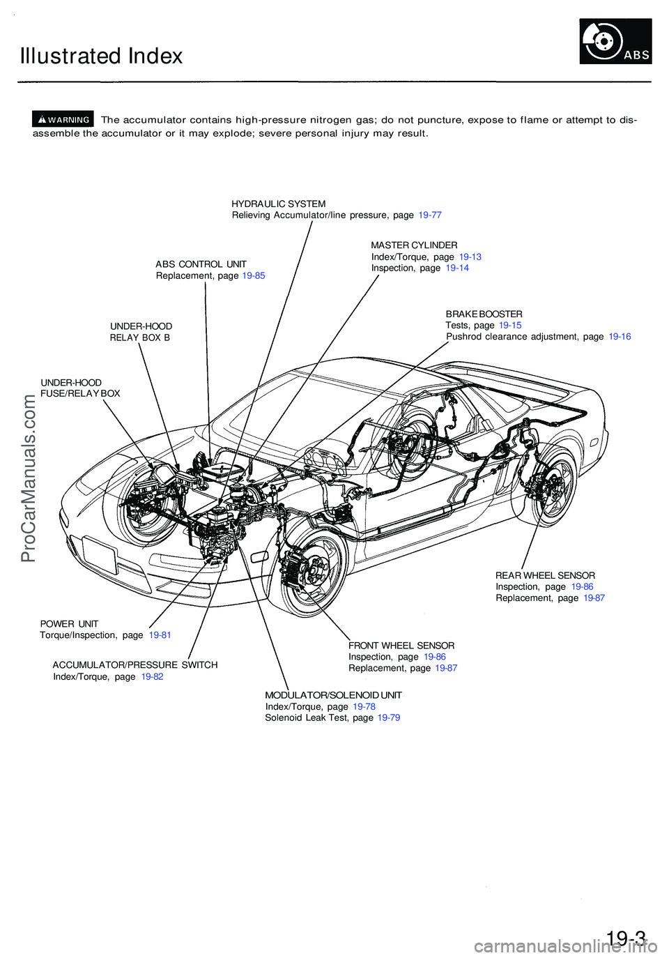
Illustrated Inde x
The accumulato r contain s high-pressur e nitroge n gas ; d o no t puncture , expos e t o flam e o r attemp t t o dis -
assembl e th e accumulato r o r i t ma y explode ; sever e persona l injur y ma y result .
HYDRAULI C SYSTE M
Relievin g Accumulator/lin e pressure , pag e 19-7 7
AB S CONTRO L UNI T
Replacement , pag e 19-8 5 MASTE
R CYLINDE R
Index/Torque , pag e 19-1 3
Inspection , pag e 19-1 4
UNDER-HOO D
RELAY BO X B
BRAK E BOOSTE R
Tests , pag e 19-1 5
Pushro d clearanc e adjustment , pag e 19-1 6
UNDER-HOO D
FUSE/RELA Y BO X
REAR WHEE L SENSO R
Inspection , pag e 19-8 6
Replacement , pag e 19-8 7
POWE R UNI T
Torque/Inspection , pag e 19-81
ACCUMULATOR/PRESSUR E SWITC H
Index/Torque , pag e 19-8 2 FRON
T WHEE L SENSO R
Inspection , pag e 19-8 6
Replacement , pag e 19-8 7
MODULATOR/SOLENOI D UNI TIndex/Torque , pag e 19-7 8
Solenoi d Lea k Test , pag e 19-7 9
19-3
ProCarManuals.com
Page 982 of 1503
Inspection and Adjustment
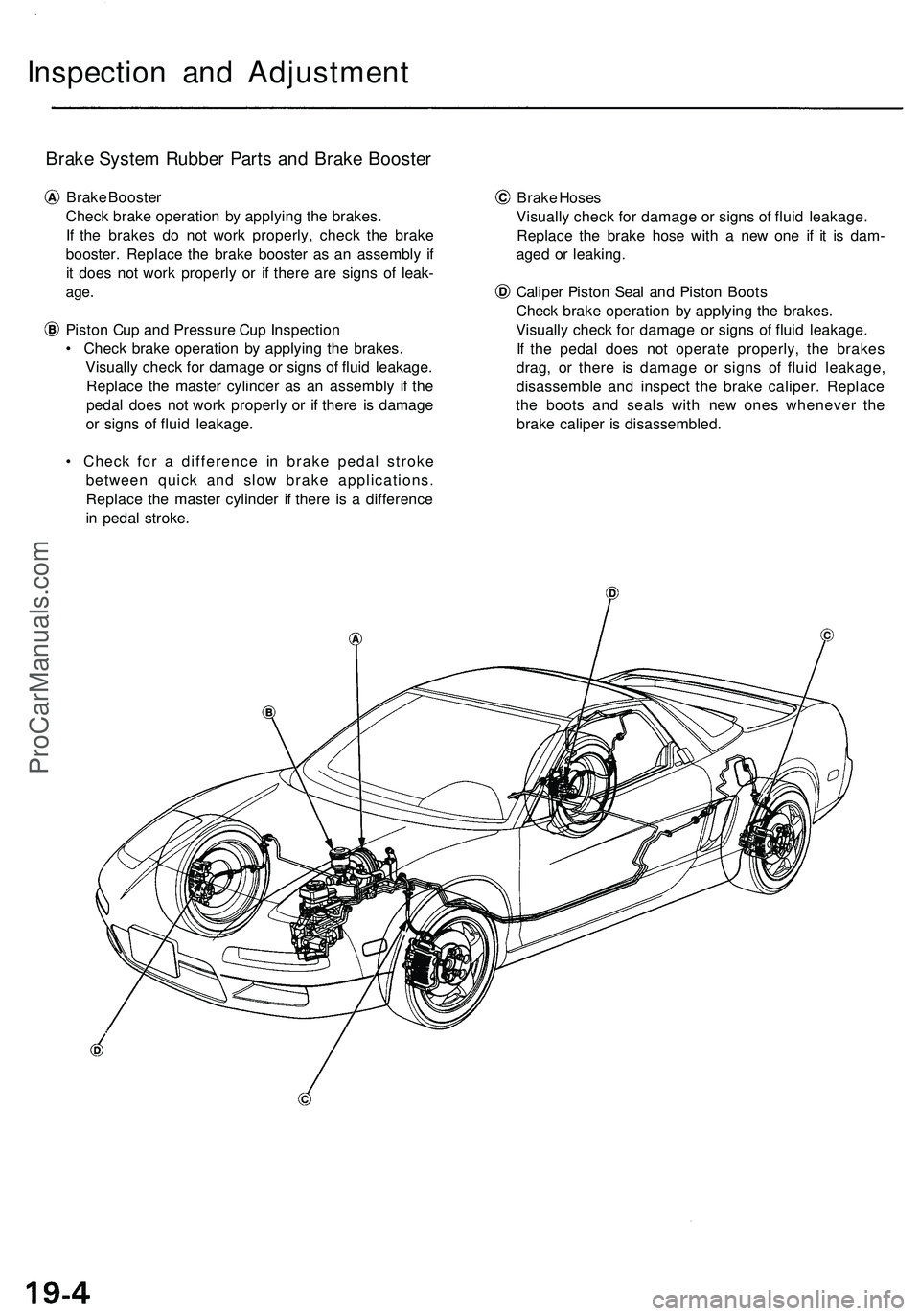
Brake System Rubber Parts and Brake Booster
Brake Booster
Check brake operation by applying the brakes.
If the brakes do not work properly, check the brake
booster. Replace the brake booster as an assembly if
it does not work properly or if there are signs of leak-
age.
Piston Cup and Pressure Cup Inspection
• Check brake operation by applying the brakes.
Visually check for damage or signs of fluid leakage.
Replace the master cylinder as an assembly if the
pedal does not work properly or if there is damage
or signs of fluid leakage.
• Check for a difference in brake pedal stroke
between quick and slow brake applications.
Replace the master cylinder if there is a difference
in pedal stroke.
Brake Hoses
Visually check for damage or signs of fluid leakage.
Replace the brake hose with a new one if it is dam-
aged or leaking.
Caliper Piston Seal and Piston Boots
Check brake operation by applying the brakes.
Visually check for damage or signs of fluid leakage.
If the pedal does not operate properly, the brakes
drag, or there is damage or signs of fluid leakage,
disassemble and inspect the brake caliper. Replace
the boots and seals with new ones whenever the
brake caliper is disassembled.ProCarManuals.com
Page 983 of 1503
Pedal Heigh t
Adjustmen t
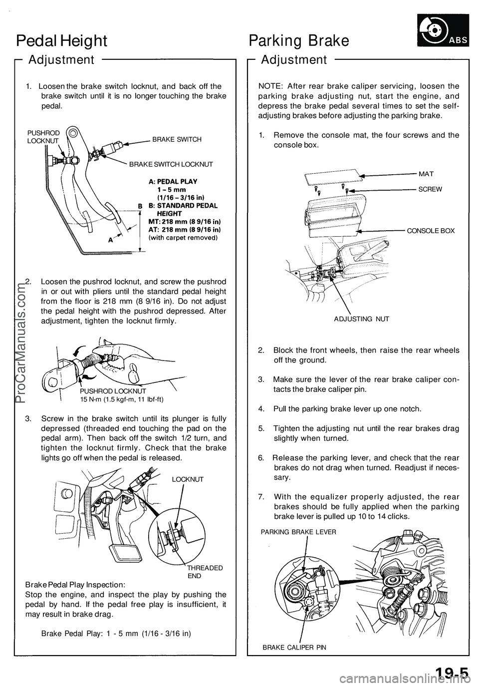
1. Lo osen th e brak e switc h locknut , an d bac k of f th e
brak e switc h unti l i t i s n o longe r touchin g th e brak e
pedal .
PUSHRO D
LOCKNU TBRAKE SWITC H
BRAKE SWITC H LOCKNU T
2. Loose n th e pushro d locknut , an d scre w th e pushro d
i n o r ou t wit h plier s unti l th e standar d peda l heigh t
fro m th e floo r i s 21 8 m m (8 9/1 6 in) . D o no t adjus t
th e peda l heigh t wit h th e pushro d depressed . Afte r
adjustment , tighte n th e locknu t firmly .
PUSHRO D LOCKNU T
1 5 N- m (1. 5 kgf-m , 1 1 Ibf-ft )
3. Scre w in th e brak e switc h unti l it s plunge r i s full y
depresse d (threade d en d touchin g th e pa d o n th e
peda l arm) . The n bac k of f th e switc h 1/ 2 turn , an d
tighte n th e locknu t firmly . Chec k tha t th e brak e
light s g o of f whe n th e peda l i s released .
LOCKNUT
THREADE DEND
Brak e Peda l Pla y Inspection :
Sto p th e engine , an d inspec t th e pla y b y pushin g th e
peda l b y hand . I f th e peda l fre e pla y i s insufficient , i t
ma y resul t i n brak e drag .
Brake Peda l Play : 1 - 5 m m (1/1 6 - 3/1 6 in )
Parkin g Brak e
Adjustmen t
NOTE: Afte r rea r brak e calipe r servicing , loose n th e
parkin g brak e adjustin g nut , star t th e engine , an d
depres s th e brak e peda l severa l time s t o se t th e self -
adjustin g brake s befor e adjustin g th e parkin g brake .
1 . Remov e th e consol e mat , th e fou r screw s an d th e
consol e box .
CONSOL E BO X
ADJUSTIN G NU T
2. Bloc k th e fron t wheels , the n rais e th e rea r wheel s
of f th e ground .
3 . Mak e sur e th e leve r o f th e rea r brak e calipe r con -
tact s th e brak e calipe r pin .
4 . Pul l th e parkin g brak e leve r u p on e notch .
5 . Tighte n th e adjustin g nu t unti l th e rea r brake s dra g
slightl y whe n turned .
6 . Releas e th e parkin g lever , an d chec k tha t th e rea r
brake s d o no t dra g whe n turned . Readjus t i f neces -
sary.
7. Wit h th e equalize r properl y adjusted , th e rea r
brake s shoul d b e full y applie d whe n th e parkin g
brak e leve r i s pulle d u p 1 0 to 1 4 clicks .
PARKIN G BRAK E LEVE R
BRAKE CALIPE R PI N
MA T
SCRE W
ProCarManuals.com
Page 984 of 1503
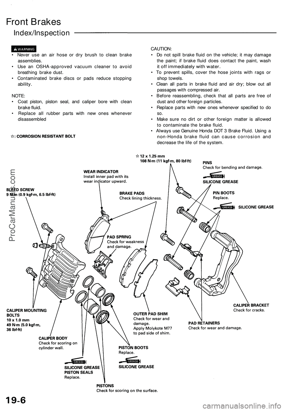
Front Brakes
Index/Inspection
• Never use an air hose or dry brush to clean brake
assemblies.
• Use an OSHA-approved vacuum cleaner to avoid
breathing brake dust.
• Contaminated brake discs or pads reduce stopping
ability.
NOTE:
• Coat piston, piston seal, and caliper bore with clean
brake fluid.
• Replace all rubber parts with new ones whenever
disassembled
CAUTION:
• Do not spill brake fluid on the vehicle; it may damage
the paint; if brake fluid does contact the paint, wash
it off immediately with water.
• To prevent spills, cover the hose joints with rags or
shop towels.
• Clean all parts in brake fluid and air dry; blow out all
passages with compressed air.
• Before reassembling, check that all parts are free of
dust and other foreign particles.
• Replace parts with new ones whenever specified to do
so.
• Make sure no dirt or other foreign matter is allowed
to contaminate the brake fluid.
• Always use Genuine Honda DOT 3 Brake Fluid. Using a
non-Honda brake fluid can cause corrosion and
decrease the life of the system.ProCarManuals.com
Page 985 of 1503
Front Brak e Pad s
Inspection/Replacemen t
• Neve r us e a n ai r hos e o r dr y brus h t o clea n brak e
assemblies .
• Us e a n OSHA-approve d vacuu m cleane r t o avoi d
breathin g brak e dust .
1 . Loose n th e fron t whee l nut s slightly , the n rais e eac h
sid e o f th e ca r an d suppor t i t o n safet y stand s (se e
pag e 1-10 throug h 1-12 ). Remov e th e fron t wheels .
2 . I f th e brak e pa d thicknes s i s les s tha n servic e limi t
a t ste p 5 , replac e th e fron t pad s a s a set . 3
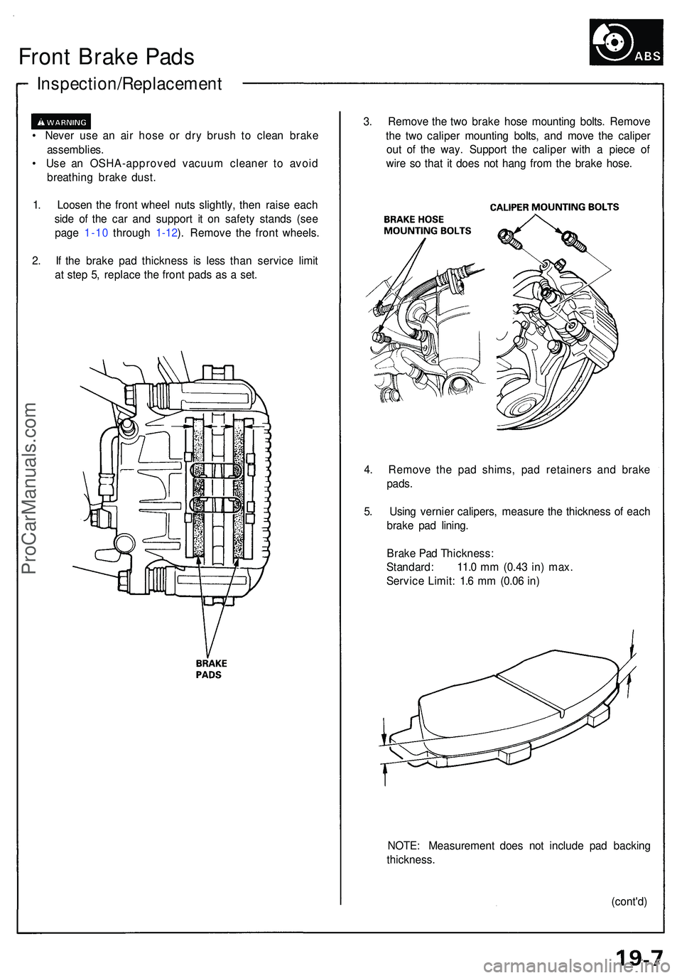
. Remov e th e tw o brak e hos e mountin g bolts . Remov e
th e tw o calipe r mountin g bolts , an d mov e th e calipe r
ou t o f th e way . Suppor t th e calipe r wit h a piec e o f
wir e s o tha t i t doe s no t han g fro m th e brak e hose .
4 . Remov e th e pa d shims , pa d retainer s an d brak e
pads .
5 . Usin g vernie r calipers , measur e th e thicknes s o f eac h
brak e pa d lining .
Brak e Pa d Thickness :
Standard : 11. 0 m m (0.4 3 in ) max .
Servic e Limit : 1. 6 m m (0.0 6 in )
NOTE : Measuremen t doe s no t includ e pa d backin g
thickness .
(cont'd)
ProCarManuals.com
Page 986 of 1503
Inspection/Replacement (cont'd )
Front Brak e Pad s
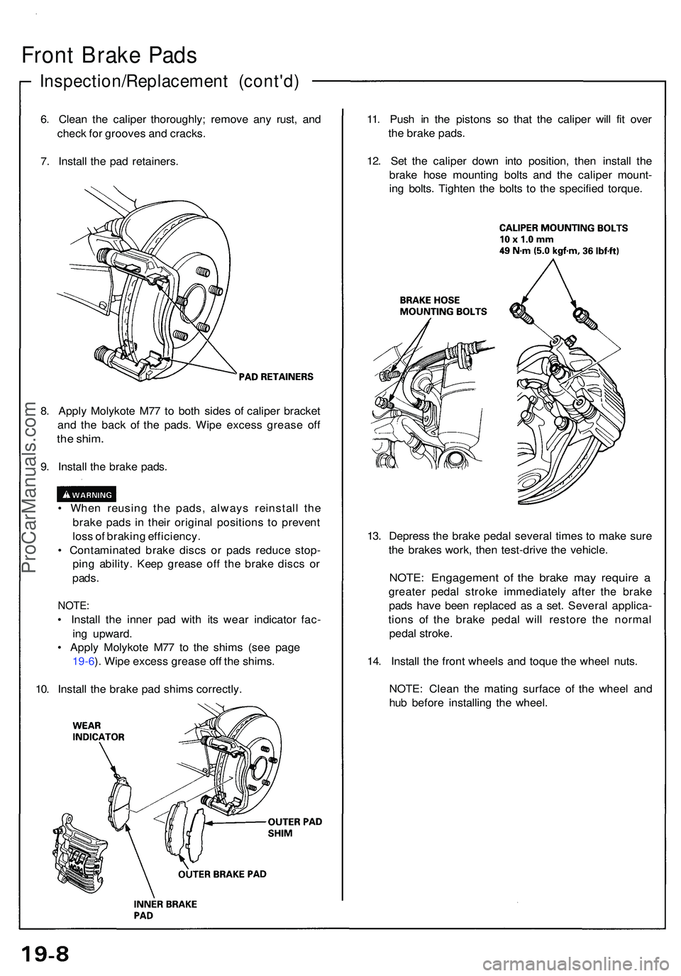
6. Clea n th e calipe r thoroughly ; remov e an y rust , an d
chec k fo r groove s an d cracks .
7 . Instal l th e pa d retainers . 11
. Pus h i n th e piston s s o tha t th e calipe r wil l fi t ove r
th e brak e pads .
12 . Se t th e calipe r dow n int o position , the n instal l th e
brak e hos e mountin g bolt s an d th e calipe r mount -
in g bolts . Tighte n th e bolt s t o th e specifie d torque .
8 . Appl y Molykot e M7 7 t o bot h side s o f calipe r bracke t
an d th e bac k o f th e pads . Wip e exces s greas e of f
the shim .
9. Instal l th e brak e pads .
• Whe n reusin g th e pads , alway s reinstal l th e
brak e pad s i n thei r origina l position s t o preven t
los s o f brakin g efficiency .
• Contaminate d brak e disc s o r pad s reduc e stop -
pin g ability . Kee p greas e of f th e brak e disc s o r
pads .
NOTE :
• Instal l th e inne r pa d wit h it s wea r indicator fac-
in g upward .
• Appl y Molykot e M7 7 t o th e shim s (se e pag e
19-6 ). Wip e exces s greas e of f th e shims .
10 . Instal l th e brak e pa d shim s correctly . 13
. Depres s th e brak e peda l severa l time s t o mak e sur e
th e brake s work , the n test-driv e th e vehicle .
NOTE: Engagemen t o f th e brak e ma y requir e a
greate r peda l strok e immediatel y afte r th e brak e
pad s hav e bee n replace d a s a set . Severa l applica -
tion s of the brak e peda l wil l restor e th e norma l
peda l stroke .
14 . Instal l th e fron t wheel s an d toqu e th e whee l nuts .
NOTE : Clea n th e matin g surfac e o f th e whee l an d
hu b befor e installin g th e wheel .
ProCarManuals.com
Page 987 of 1503
Disassembly
Front Caliper
• Never use an air hose or dry brush to clean brake
assemblies.
• Use an OSHA-approved vacuum cleaner to avoid
breathing brake dust.
CAUTION:
• Do not spill brake fluid on the vehicle; it may damage
the paint; if brake fluid does contact the paint, wash
it off immediately with water.
• To prevent spills, cover the hose joints with rags or
shop towels.
• Clean all parts in brake fluid and air dry; blow out all
passages with compressed air.
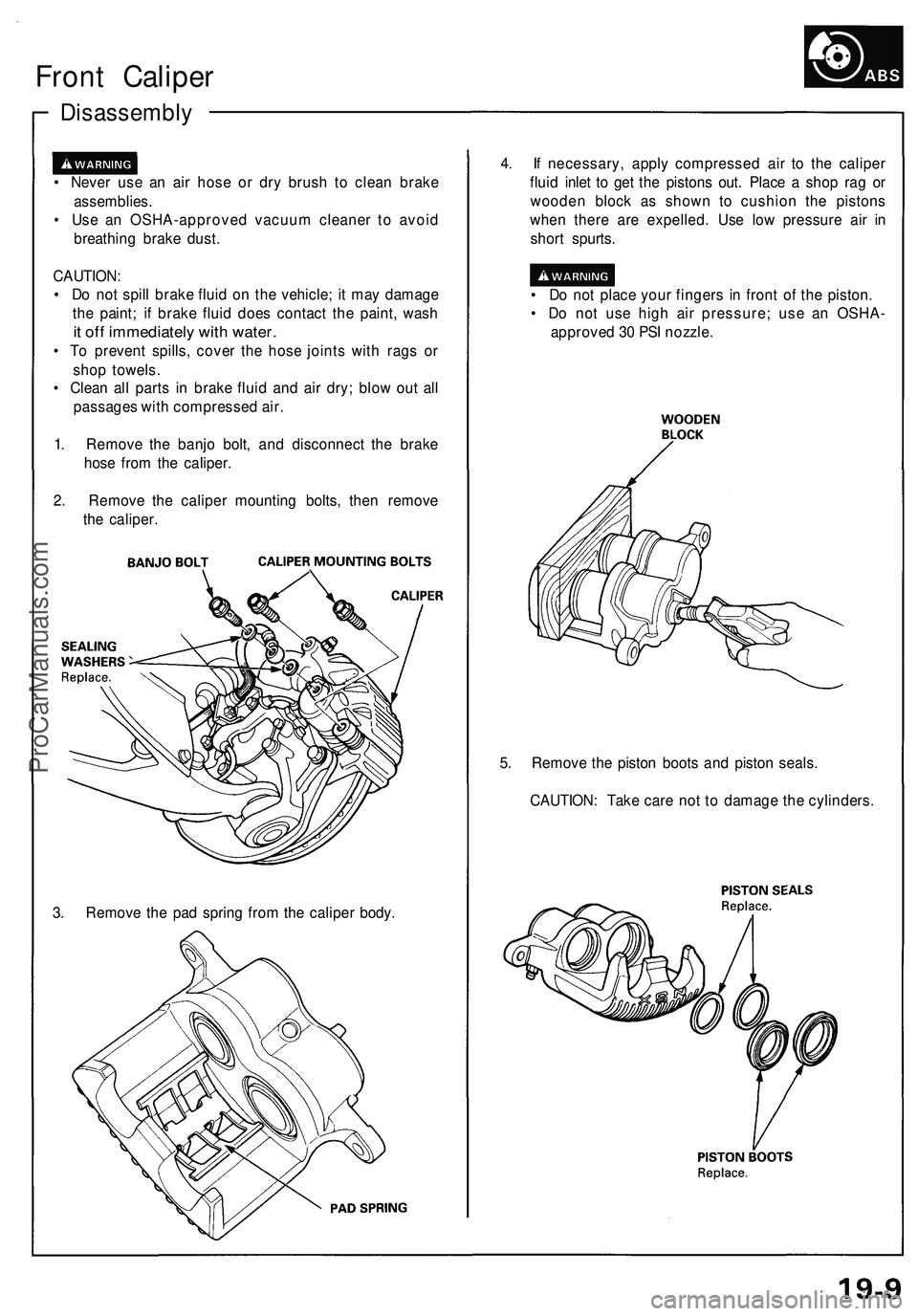
1. Remove the banjo bolt, and disconnect the brake
hose from the caliper.
2. Remove the caliper mounting bolts, then remove
the caliper.
4. If necessary, apply compressed air to the caliper
fluid inlet to get the pistons out. Place a shop rag or
wooden block as shown to cushion the pistons
when there are expelled. Use low pressure air in
short spurts.
• Do not place your fingers in front of the piston.
• Do not use high air pressure; use an OSHA-
approved 30 PSI nozzle.
3. Remove the pad spring from the caliper body.
5. Remove the piston boots and piston seals.
CAUTION: Take care not to damage the cylinders.ProCarManuals.com
Page 988 of 1503
Reassembly
Front Calipe r
CAUTION :
• Befor e reassembling , chec k tha t al l part s ar e fre e o f
dus t an d othe r foreig n particles .
• Replac e part s wit h ne w one s wheneve r specifie d t o
do so .
• Alway s us e Genuin e Hond a DO T 3 Brak e Fluid . Usin g
a non-Hond a brak e flui d ca n caus e corrosio n an d
decreas e th e lif e o f th e system .
• Mak e sur e n o dir t o r othe r foreig n matte r i s allowe d
t o contaminat e th e brak e fluid .
• D o no t spil l brak e flui d o n th e vehicle ; i t ma y damag e
th e paint ; i f brak e flui d doe s contac t th e paint , was h
i t of f immediatel y wit h water .
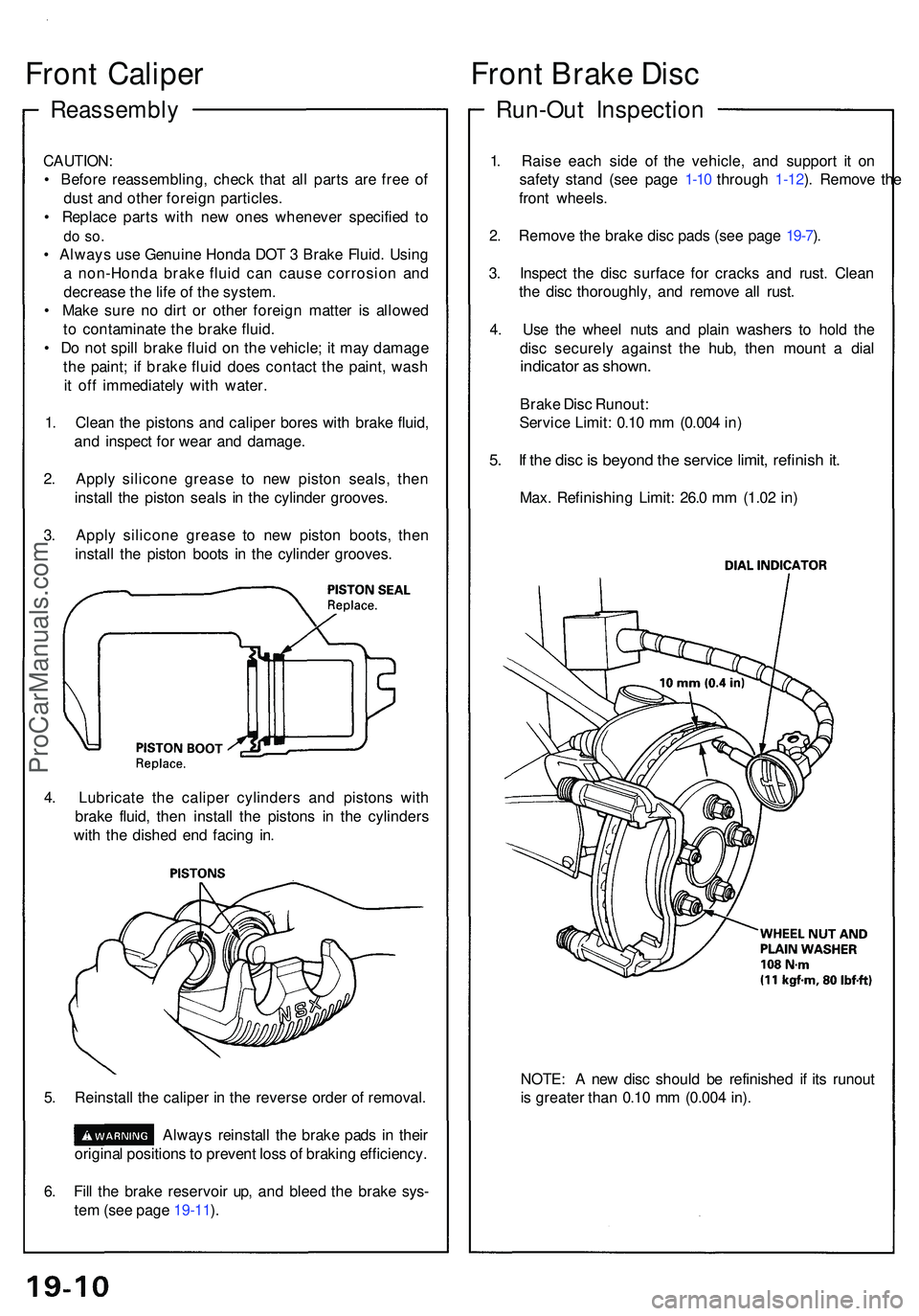
1 . Clea n th e piston s an d calipe r bore s wit h brak e fluid ,
an d inspec t fo r wea r an d damage .
2 . Appl y silicon e greas e t o ne w pisto n seals , the n
instal l th e pisto n seal s i n th e cylinde r grooves .
3 . Appl y silicon e greas e t o ne w pisto n boots , the n
instal l th e pisto n boot s i n th e cylinde r grooves .
Run-Out Inspectio n
Front Brak e Dis c
1. Rais e eac h sid e of the vehicle , an d suppor t i t o n
safet y stan d (se e pag e 1-10 throug h 1-12 ). Remov e th e
fron t wheels .
2 . Remov e th e brak e dis c pad s (se e pag e 19-7 ).
3 . Inspec t th e dis c surfac e fo r crack s an d rust . Clean
th e dis c thoroughly , an d remov e al l rust .
4 . Us e th e whee l nut s an d plai n washer s t o hol d th e
dis c securel y agains t th e hub , the n moun t a dia l
indicato r a s shown .
Brake Dis c Runout :
Servic e Limit : 0.1 0 m m (0.00 4 in )
5. I f th e dis c is beyon d th e servic e limit , refinis h it .
Max . Refinishin g Limit : 26. 0 m m (1.0 2 in )
4 . Lubricat e th e calipe r cylinder s an d piston s wit h
brak e fluid , the n instal l th e piston s i n th e cylinder s
wit h th e dishe d en d facin g in .
5 . Reinstal l th e calipe r i n th e revers e orde r o f removal .
Always reinstal l th e brak e pad s in thei r
origina l position s to preven t los s o f brakin g efficiency .
6 . Fil l th e brak e reservoi r up , an d blee d th e brak e sys -
te m (se e pag e 19-11 ). NOTE
: A ne w dis c shoul d b e refinishe d i f it s runou t
i s greate r tha n 0.1 0 m m (0.00 4 in) .
ProCarManuals.com
Page 989 of 1503
Thickness an d Parallelis m
Inspectio n
1. Rais e eac h sid e o f th e vehicle , an d suppor t i t o n
safet y stand s (se e pag e 1-10 throug h 1-12 ). Remov e th e
fron t wheels .
2. Remov e th e brak e dis c pad s (se e pag e 19-7 ).
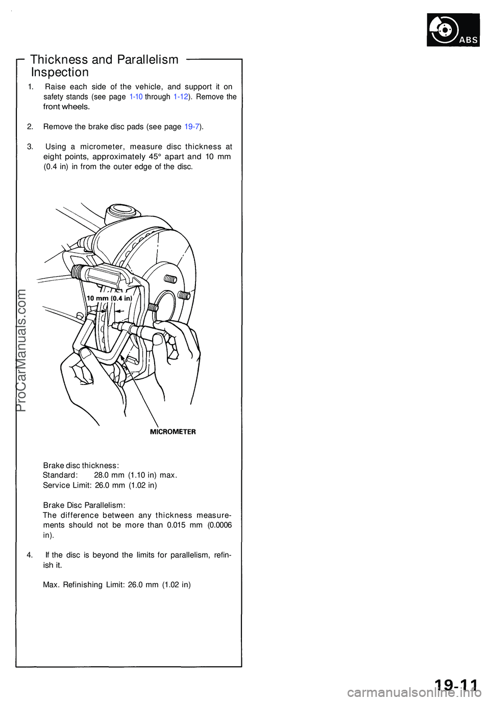
3 . Usin g a micrometer , measur e dis c thicknes s a t
eigh t points , approximatel y 45 ° apar t an d 1 0 m m
(0.4 in ) i n fro m th e oute r edg e o f th e disc .
Brak e dis c thickness :
Standard : 28. 0 m m (1.1 0 in ) max .
Servic e Limit : 26. 0 m m (1.0 2 in )
Brak e Dis c Parallelism :
Th e differenc e betwee n an y thicknes s measure -
ment s shoul d no t b e mor e tha n 0.01 5 m m (0.000 6
in).
4. I f th e dis c i s beyon d th e limit s fo r parallelism , refin -
ish it .
Max . Refinishin g Limit : 26. 0 m m (1.0 2 in )
ProCarManuals.com
Page 990 of 1503
Bleeding
CAUTION:
• Always use Genuine Honda DOT 3 Brake Fluid. Using
a non-Honda brake fluid can cause corrosion and
decrease the life of the system.
• Make sure no dirt or other foreign matter is allowed
to contaminate the brake fluid.
• Do not spill brake fluid on the vehicle, it may damage
the paint; if brake fluid does contact the paint, wash
it off immediately with water.
NOTE: The reservoir on the master cylinder must be full
at the start of bleeding procedure, and checked after
bleeding each brake caliper. Add fluid as required.
Always use Genuine Honda DOT 3 Brake Fluid. Using a
non-Honda brake fluid can cause corrosion and
decrease the life of the system.
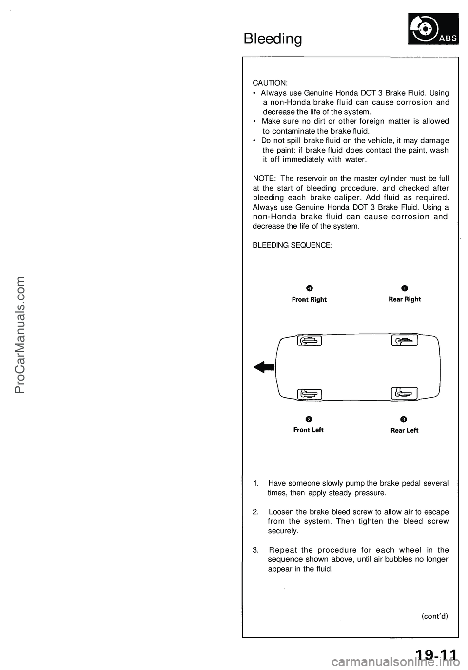
BLEEDING SEQUENCE:
1. Have someone slowly pump the brake pedal several
times, then apply steady pressure.
2. Loosen the brake bleed screw to allow air to escape
from the system. Then tighten the bleed screw
securely.
3. Repeat the procedure for each wheel in the
sequence shown above, until air bubbles no longer
appear in the fluid.ProCarManuals.com