ACURA NSX 1997 Service Repair Manual
Manufacturer: ACURA, Model Year: 1997, Model line: NSX, Model: ACURA NSX 1997Pages: 1503, PDF Size: 57.08 MB
Page 141 of 1503
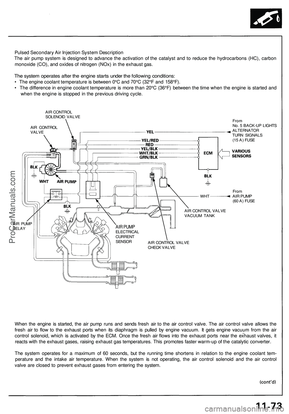
Pulsed Secondary Air Injection System Description
The air pump system is designed to advance the activation of the catalyst and to reduce the hydrocarbons (HC), carbon
monoxide (CO), and oxides of nitrogen (NOx) in the exhaust gas.
The system operates after the engine starts under the following conditions:
• The engine coolant temperature is between 0°C and 70°C (32°F and 158°F).
• The difference in engine coolant temperature is more than 20°C (36°F) between the time when the engine is started and
when the engine is stopped in the previous driving cycle.
AIR CONTROL
SOLENOID VALVE
AIR CONTROL
VALVE
WHT
AIR PUMP
RELAY
From
No. 5 BACK-UP LIGHTS
ALTERNATOR
TURN SIGNALS
(15 A) FUSE
From
AIR PUMP
(60 A) FUSE
AIR CONTROL VALVE
VACUUM TANK
AIR CONTROL VALVE
CHECK VALVE
When the engine is started, the air pump runs and sends fresh air to the air control valve. The air control valve allows the
fresh air to flow to the exhaust ports when its diaphragm is pulled by engine vacuum. It gets engine vacuum from the air
control solenoid, which is activated by the ECM. Once the fresh air flows into the exhaust ports near the exhaust valves, it
reacts with the exhaust gases, raising exhaust gas temperatures. This promotes faster warm-up of the catalytic converter.
The system operates for a maximum of 60 seconds, but the running time shortens in relation to the engine coolant tem-
perature and the intake air temperature. When the system is not operating, the air control solenoid and the air control
valve are closed to prevent exhaust gases from entering the system.
AIR PUMP
ELECTRICAL
CURRENT
SENSORProCarManuals.com
Page 142 of 1503
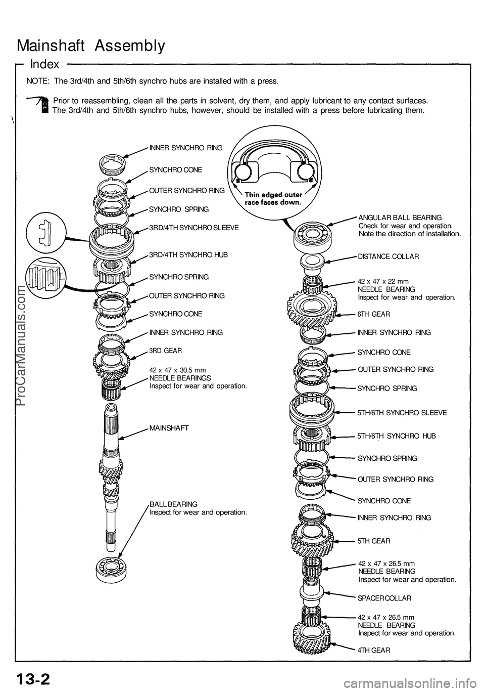
Mainshaft Assembl y
Index
NOTE : Th e 3rd/4t h an d 5th/6t h synchr o hub s ar e installe d wit h a press .
Prio r t o reassembling , clea n al l th e part s i n solvent , dr y them , an d appl y lubrican t t o an y contac t surfaces .
Th e 3rd/4t h an d 5th/6t h synchr o hubs , however , shoul d b e installe d wit h a pres s befor e lubricatin g them .
INNER SYNCHR O RIN G
SYNCHR O CON E
OUTE R SYNCHR O RIN G
SYNCHR O SPRIN G
3RD/4T H SYNCHR O SLEEV E
3RD/4T H SYNCHR O HU B
SYNCHR O SPRIN G
OUTE R SYNCHR O RIN G
SYNCHR O CON E
INNE R SYNCHR O RIN G
3RD GEA R
42 x 47 x 30. 5 mmNEEDL E BEARING S
Inspec t fo r wea r an d operation .
MAINSHAF T
BALL BEARIN GInspect fo r wea r an d operation .
ANGULAR BAL L BEARIN G
Chec k fo r wea r an d operation .
Note th e directio n o f installation .
DISTANCE COLLA R
42 x 47 x 22 m mNEEDL E BEARIN G
Inspec t fo r wea r an d operation .
6TH GEA R
INNER SYNCHR O RIN G
SYNCHR O CON E
OUTE R SYNCHR O RIN G
SYNCHR O SPRIN G
5TH/6T H SYNCHR O SLEEV E
5TH/6T H SYNCHR O HU B
SYNCHR O SPRIN G
OUTER SYNCHR O RIN G
SYNCHR O CON E
INNE R SYNCHR O RIN G
5T H GEA R
42 x 47 x 26. 5 mmNEEDL E BEARIN GInspect fo r wea r an d operation .
SPACER COLLA R
42 x 47 x 26. 5 mmNEEDL E BEARIN GInspect fo r wea r an d operation .
4TH GEA R
ProCarManuals.com
Page 143 of 1503
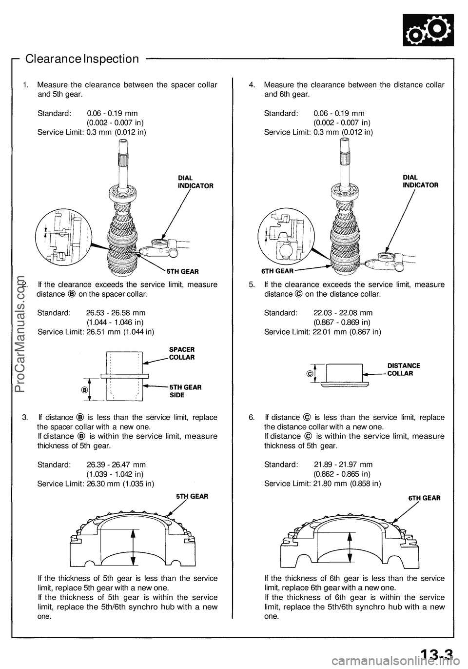
Clearance Inspectio n
1. Measur e th e clearanc e betwee n th e space r colla r
an d 5t h gear .
Standard : 0.0 6 - 0.1 9 m m
(0.00 2 - 0.00 7 in )
Servic e Limit : 0. 3 m m (0.01 2 in )
2 . I f th e clearanc e exceed s th e servic e limit , measur e
distance o n th e space r collar .
Standard : 26.5 3 - 26.5 8 m m
(1.04 4 - 1.04 6 in )
Servic e Limit : 26.5 1 m m (1.04 4 in )
3. I f distanc e i s les s tha n th e servic e limit , replac e
th e space r colla r wit h a ne w one .
If distanc e i s withi n th e servic e limit , measur e
thickness o f 5t h gear .
Standard : 26.3 9 - 26.4 7 m m
(1.03 9 - 1.04 2 in )
Servic e Limit : 26.3 0 m m (1.03 5 in )
I f th e thicknes s o f 5t h gea r i s les s tha n th e servic e
limit, replac e 5t h gea r wit h a ne w one .
If th e thicknes s o f 5t h gea r i s withi n th e servic e
limit, replac e th e 5th/6t h synchr o hu b wit h a ne w
one .
4. Measur e th e clearanc e betwee n th e distanc e colla r
an d 6t h gear .
Standard : 0.0 6 - 0.1 9 m m
(0.00 2 - 0.00 7 in )
Servic e Limit : 0. 3 m m (0.01 2 in )
5 . I f th e clearanc e exceed s th e servic e limit , measur e
distance o n th e distanc e collar .
Standard : 22.0 3 - 22.0 8 m m
(0.86 7 - 0.86 9 in )
Servic e Limit : 22.0 1 m m (0.86 7 in )
6. I f distanc e i s les s tha n th e servic e limit , replac e
the distanc e colla r wit h a ne w one .
If distanc e i s withi n th e servic e limit , measur e
thickness o f 5t h gear .
Standard : 21.8 9 - 21.9 7 m m
(0.86 2 - 0.86 5 in )
Servic e Limit : 21.8 0 m m (0.85 8 in )
I f th e thicknes s o f 6t h gea r i s les s tha n th e servic e
limit, replac e 6t h gea r wit h a ne w one .
If th e thicknes s o f 6t h gea r i s withi n th e servic e
limit, replac e th e 5th/6t h synchr o hu b wit h a ne w
one .
ProCarManuals.com
Page 144 of 1503
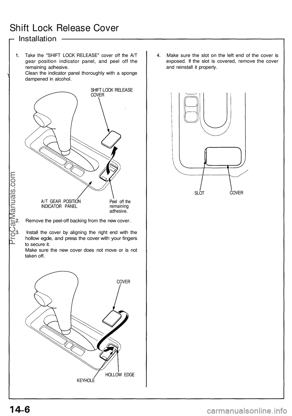
Shift Loc k Releas e Cove r
Installatio n ——————————
Take th e "SHIF T LOC K RELEASE " cove r of f th e A/ T
gea r positio n indicato r panel , an d pee l of f th e
remainin g adhesive .
Clea n th e indicato r pane l thoroughl y wit h a spong e
dampene d in alcohol .
SHIFT LOC K RELEAS ECOVER
A/ T GEA R POSITIO N
INDICATO R PANE L Pee
l of f th e
remainin gadhesive .
2. Remov e th e peel-of f backin g fro m th e ne w cover .
3 . Instal l th e cove r b y alignin g th e righ t en d wit h th e
hollo w egde , an d pres s th e cove r wit h you r finger s
to secur e it .
Mak e sur e th e ne w cove r doe s no t mov e o r i s no t
take n off .
COVE R
HOLLO W EDG E
KEYHOL E
4. Mak e sur e th e slo t o n th e lef t en d o f th e cove r i s
exposed . I f th e slo t i s covered , remov e th e cove r
an d reinstal l i t properly .
SLOT COVE
R
ProCarManuals.com
Page 145 of 1503
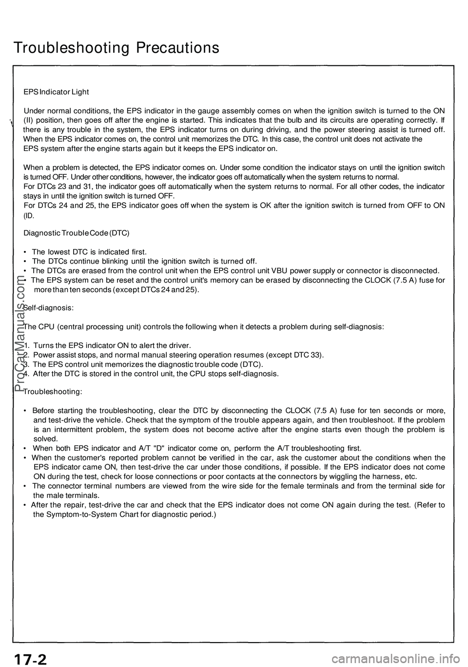
Troubleshooting Precaution s
EPS Indicato r Ligh t
Unde r norma l conditions , th e EP S indicato r i n th e gaug e assembl y come s o n whe n th e ignitio n switc h is turne d t o th e O N
(II ) position , the n goe s of f afte r th e engin e i s started . Thi s indicate s tha t th e bul b an d it s circuit s ar e operatin g correctly . I f
ther e i s an y troubl e i n th e system , th e EP S indicato r turn s o n durin g driving , an d th e powe r steerin g assis t i s turne d off .
Whe n th e EP S indicato r come s on , th e contro l uni t memorize s th e DTC . I n thi s case , th e contro l uni t doe s no t activat e th e
EP S syste m afte r th e engin e start s agai n bu t i t keep s th e EP S indicato r on .
Whe n a proble m is detected , th e EP S indicato r come s on . Unde r som e conditio n th e indicato r stay s o n unti l th e ignitio n switc h
i s turne d OFF . Unde r othe r conditions , however , th e indicato r goe s of f automaticall y whe n th e syste m return s to normal .
Fo r DTC s 2 3 an d 31 , th e indicato r goe s of f automaticall y whe n th e syste m return s t o normal . Fo r al l othe r codes , th e indicato r
stay s in unti l th e ignitio n switc h is turne d OFF .
Fo r DTC s 2 4 an d 25 , th e EP S indicato r goe s of f whe n th e syste m is O K afte r th e ignitio n switc h is turne d fro m OF F to O N
(ID .
Diagnosti c Troubl e Cod e (DTC )
• Th e lowes t DT C is indicate d first .
• Th e DTC s continu e blinkin g unti l th e ignitio n switc h i s turne d off .
• Th e DTC s ar e erase d fro m th e contro l uni t whe n th e EP S contro l uni t VB U powe r suppl y o r connecto r i s disconnected .
• Th e EP S syste m ca n b e rese t an d th e contro l unit' s memor y ca n b e erase d b y disconnectin g th e CLOC K (7. 5 A ) fus e fo r
mor e tha n te n second s (excep t DTC s 2 4 an d 25) .
Self-diagnosis :
The CP U (centra l processin g unit ) control s th e followin g whe n it detect s a proble m durin g self-diagnosis :
1 . Turn s th e EP S indicato r O N to aler t th e driver .
2 . Powe r assis t stops , an d norma l manua l steerin g operatio n resume s (excep t DT C 33) .
3 . Th e EP S contro l uni t memorize s th e diagnosti c troubl e cod e (DTC) .
4 . Afte r th e DT C is store d in th e contro l unit , th e CP U stop s self-diagnosis .
Troubleshooting :
• Befor e startin g th e troubleshooting , clea r th e DT C b y disconnectin g th e CLOC K (7. 5 A ) fus e fo r te n second s o r more ,
an d test-driv e th e vehicle . Chec k tha t th e sympto m o f th e troubl e appear s again , an d the n troubleshoot . I f th e proble m
i s a n intermitten t problem , th e syste m doe s no t becom e activ e afte r th e engin e start s eve n thoug h th e proble m is
solved .
• Whe n bot h EP S indicato r an d A/ T "D " indicato r com e on , perfor m th e A/ T troubleshootin g first .
• Whe n th e customer' s reporte d proble m canno t b e verifie d i n th e car , as k th e custome r abou t th e condition s whe n th e
EP S indicato r cam e ON , the n test-driv e th e ca r unde r thos e conditions , i f possible . I f th e EP S indicato r doe s no t com e
O N durin g th e test , chec k fo r loos e connection s o r poo r contact s a t th e connector s b y wigglin g th e harness , etc .
• Th e connecto r termina l number s ar e viewe d fro m th e wir e sid e fo r th e femal e terminal s an d fro m th e termina l sid e fo r
th e mal e terminals .
• Afte r th e repair , test-driv e th e ca r an d chec k tha t th e EP S indicato r doe s no t com e O N agai n durin g th e test . (Refe r t o
th e Symptom-to-Syste m Char t fo r diagnosti c period. )
ProCarManuals.com
Page 146 of 1503
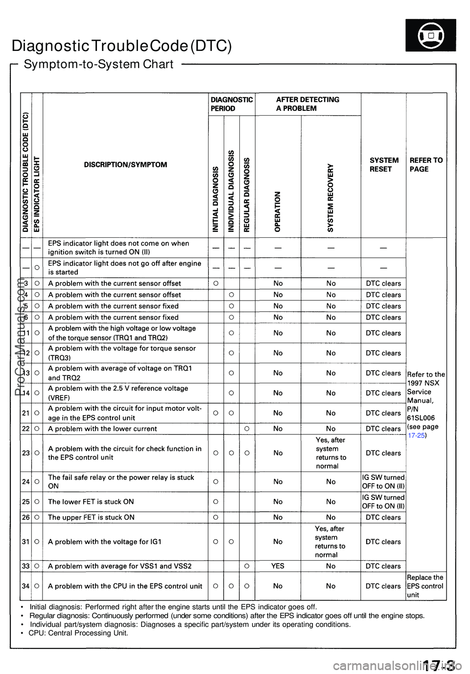
Symptom-to-System Char t
Diagnosti c Troubl e Cod e (DTC )
• Initia l diagnosis : Performe d righ t afte r th e engin e start s unti l th e EP S indicato r goe s off .
• Regula r diagnosis : Continuousl y performe d (unde r som e conditions ) afte r th e EP S indicato r goe s of f unti l th e engin e stops .
• Individua l part/syste m diagnosis: Diagnoses a specifi c part/syste m unde r it s operatin g conditions .
• CPU : Centra l Processin g Unit .
17-25
ProCarManuals.com
Page 147 of 1503
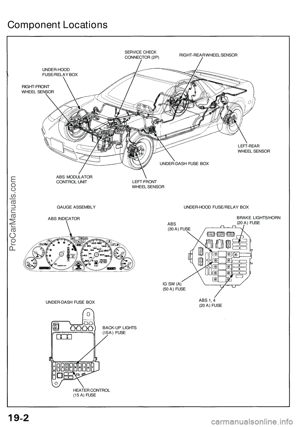
Component Location s
SERVICE CHEC KCONNECTO R (2P ) RIGHT-REA
R WHEE L SENSO R
UNDER-HOO D
FUSE/RELA Y BO X
RIGHT-FRON TWHEEL SENSO R
LEFT-REA RWHEEL SENSO R
UNDER-DAS H FUS E BO X
AB S MODULATO R
CONTROL UNI T
GAUG E ASSEMBL Y
AB S INDICATO R
LEFT-FRON TWHEEL SENSO R
UNDER-HOO D FUSE/RELA Y BO X
ABS(30 A ) FUS E
IG S W (A )(50 A ) FUS E BRAK
E LIGHTS/HOR N
(2 0 A ) FUS E
UNDER-DAS H FUS E BO X
ABS 1 , 4(2 0 A ) FUS E
BACK-U P LIGHT S
(ISA ) FUS E
HEATE R CONTRO L
(15 A) FUSE
ProCarManuals.com
Page 148 of 1503
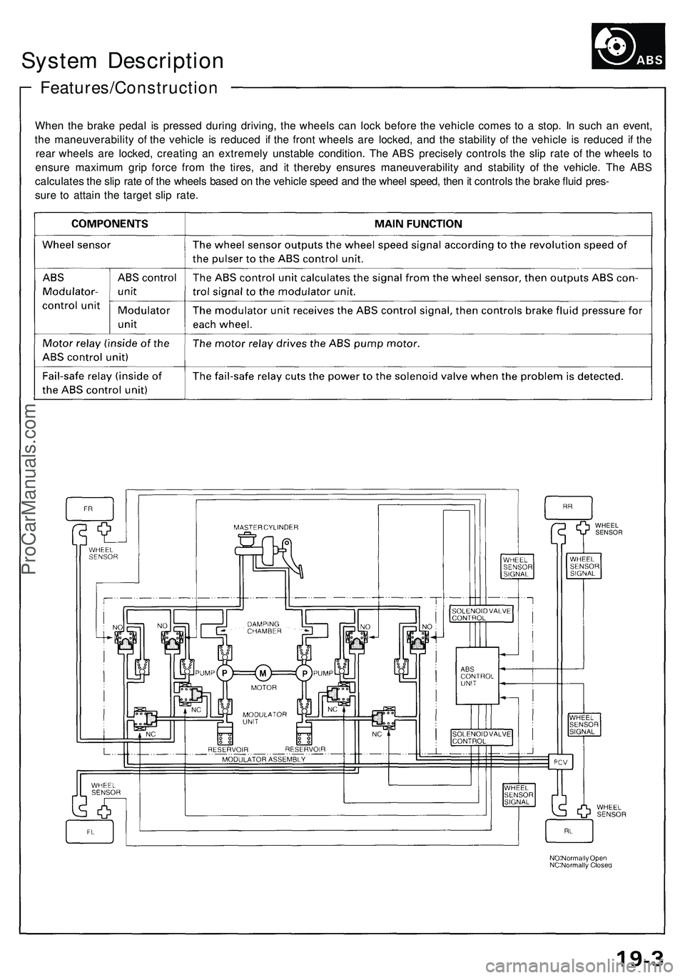
System Descriptio n
Features/Constructio n
When th e brak e peda l i s presse d durin g driving , th e wheel s ca n loc k befor e th e vehicl e come s t o a stop . I n suc h a n event ,
th e maneuverabilit y o f th e vehicl e i s reduce d i f th e fron t wheel s ar e locked , an d th e stabilit y o f th e vehicl e i s reduce d i f th e
rea r wheel s ar e locked , creatin g a n extremel y unstabl e condition . Th e AB S precisel y control s th e sli p rat e o f th e wheel s t o
ensur e maximu m gri p forc e fro m th e tires , an d i t thereb y ensure s maneuverabilit y an d stabilit y o f th e vehicle . Th e AB S
calculate s th e sli p rat e o f th e wheel s base d o n th e vehicl e spee d an d th e whee l speed , the n it control s th e brak e flui d pres -
sur e t o attai n th e targe t sli p rate .
WHEE L
SENSO R
ProCarManuals.com
Page 149 of 1503
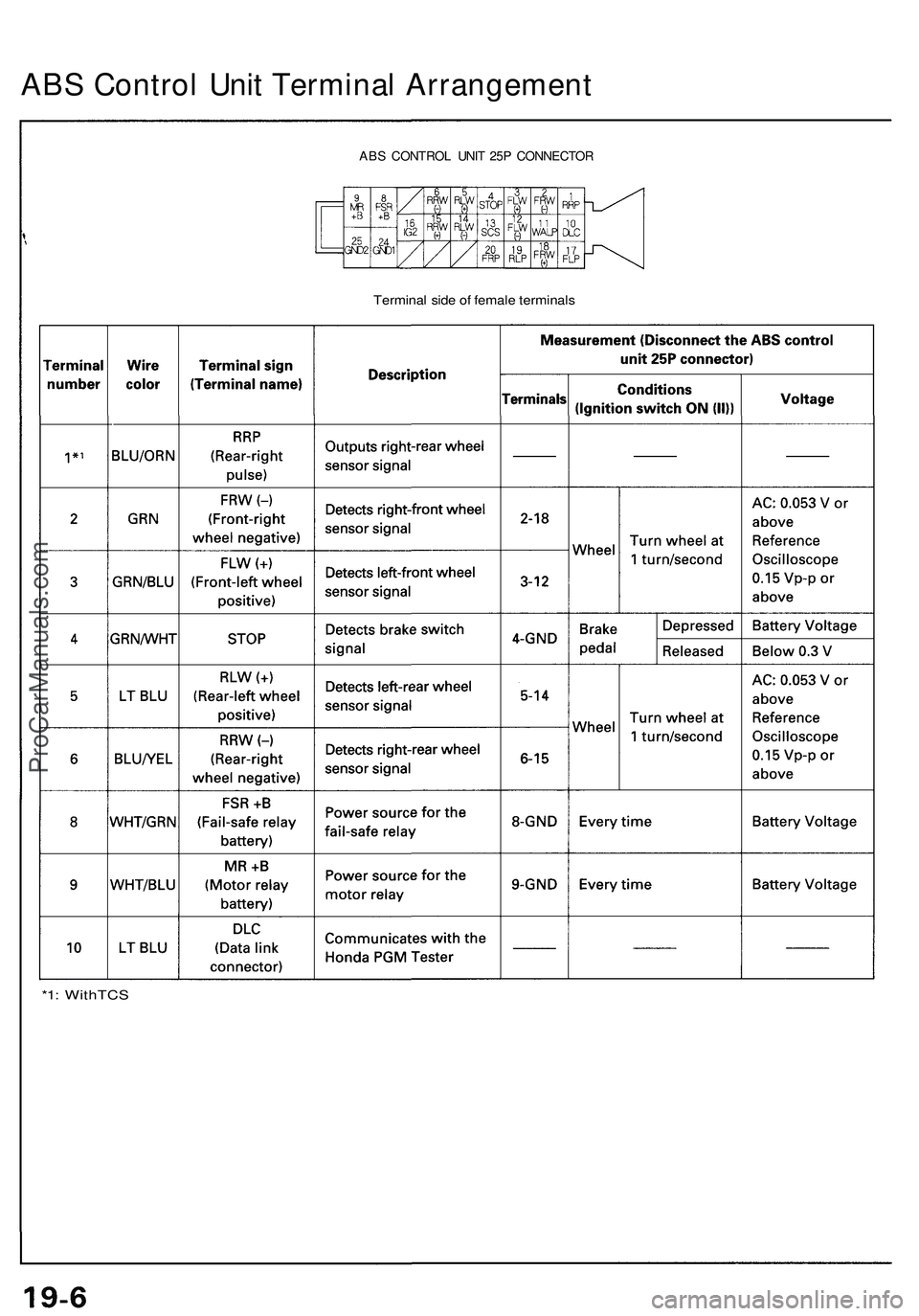
*1: WithTC S
Terminal sid e o f femal e terminal s
ABS CONTRO L UNI T 25 P CONNECTO R
ABS Contro l Uni t Termina l Arrangemen t
ProCarManuals.com
Page 150 of 1503
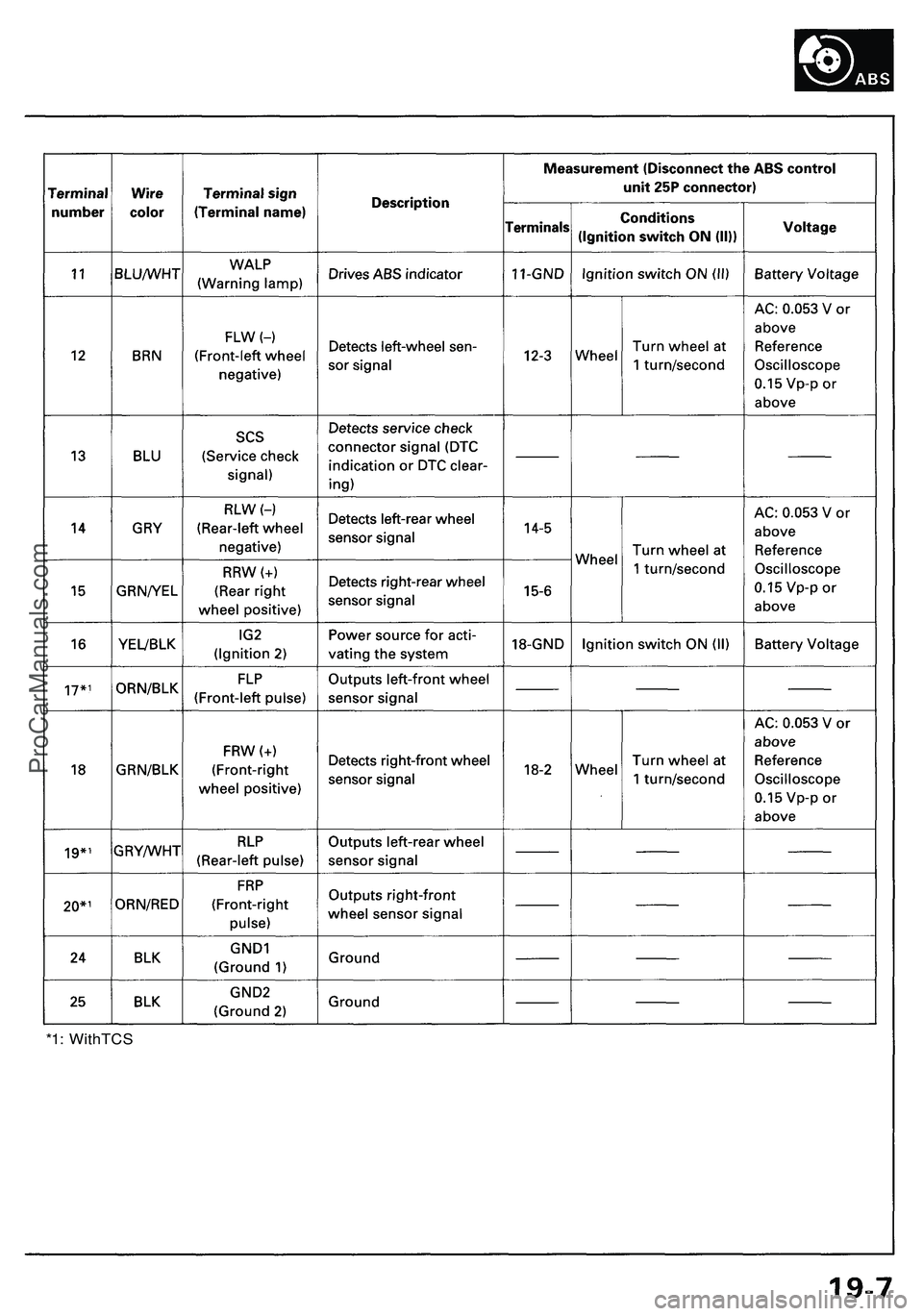
*1: WithTCSProCarManuals.com