low oil pressure ACURA NSX 1997 Service Repair Manual
[x] Cancel search | Manufacturer: ACURA, Model Year: 1997, Model line: NSX, Model: ACURA NSX 1997Pages: 1503, PDF Size: 57.08 MB
Page 573 of 1503
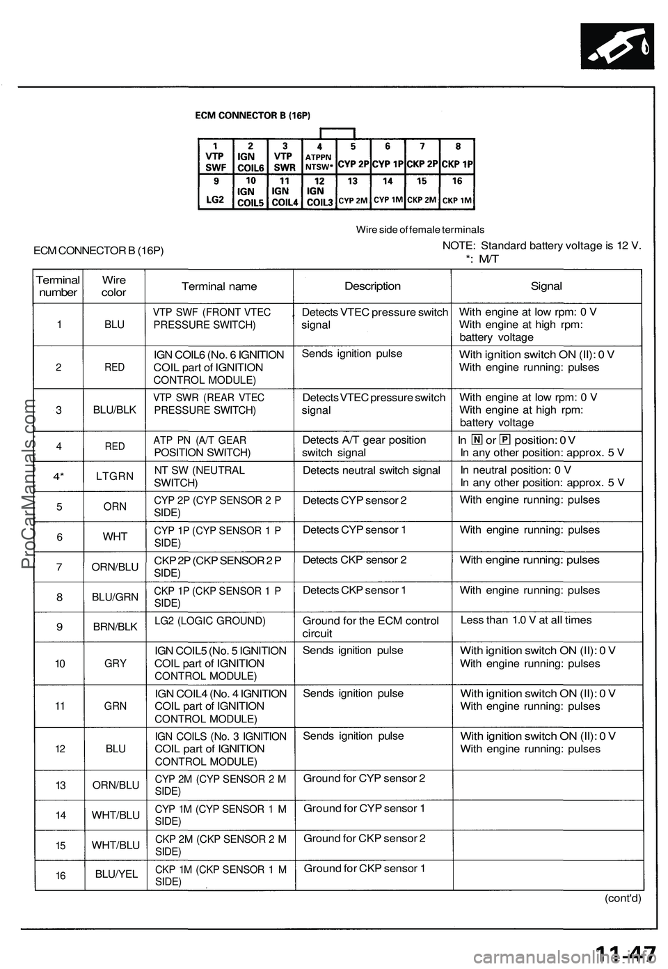
Terminal
number
1
2
3
4
4*
5
6
7
8
9
10
11
12
13
14
15
16
Wire
color
BLU
RED
BLU/BLK
RED
LTGRN
ORN
WHT
ORN/BLU
BLU/GRN
BRN/BLK
GRY
GRN
BLU
ORN/BLU
WHT/BLU
WHT/BLU
BLU/YEL
Terminal name
VTP SWF (FRONT VTEC
PRESSURE SWITCH)
IGN COIL6 (No. 6 IGNITION
COIL part of IGNITION
CONTROL MODULE)
VTP SWR (REAR VTEC
PRESSURE SWITCH)
ATP PN (A/T GEAR
POSITION SWITCH)
NT SW (NEUTRAL
SWITCH)
CYP 2P (CYP SENSOR 2 P
SIDE)
CYP 1P (CYP SENSOR 1 P
SIDE)
CKP 2P (CKP SENSOR 2 P
SIDE)
CKP 1P (CKP SENSOR 1 P
SIDE)
LG2 (LOGIC GROUND)
IGN COIL5 (No. 5 IGNITION
COIL part of IGNITION
CONTROL MODULE)
IGN COIL4 (No. 4 IGNITION
COIL part of IGNITION
CONTROL MODULE)
IGN COILS (No. 3 IGNITION
COIL part of IGNITION
CONTROL MODULE)
CYP 2M (CYP SENSOR 2 M
SIDE)
CYP 1M (CYP SENSOR 1 M
SIDE)
CKP 2M (CKP SENSOR 2 M
SIDE)
CKP 1M (CKP SENSOR 1 M
SIDE)
Description
Detects VTEC pressure switch
signal
Sends ignition pulse
Detects VTEC pressure switch
signal
Detects A/T gear position
switch signal
Detects neutral switch signal
Detects CYP sensor 2
Detects CYP sensor 1
Detects CKP sensor 2
Detects CKP sensor 1
Ground for the ECM control
circuit
Sends ignition pulse
Sends ignition pulse
Sends ignition pulse
Ground for CYP sensor 2
Ground for CYP sensor 1
Ground for CKP sensor 2
Ground for CKP sensor 1
Signal
With engine at low rpm: 0 V
With engine at high rpm:
battery voltage
With ignition switch ON (II): 0 V
With engine running: pulses
With engine at low rpm: 0 V
With engine at high rpm:
battery voltage
In or position: 0V
In any other position: approx. 5 V
In neutral position: 0 V
In any other position: approx. 5 V
With engine running: pulses
With engine running: pulses
With engine running: pulses
With engine running: pulses
Less than 1.0 V at all times
With ignition switch ON (II): 0 V
With engine running: pulses
With ignition switch ON (II): 0 V
With engine running: pulses
With ignition switch ON (II): 0 V
With engine running: pulses
(cont'd)
Wire side of female terminals
NOTE: Standard battery voltage is 12 V.
*: M/T
ECM CONNECTOR B (16P)ProCarManuals.com
Page 776 of 1503
(cont'd)
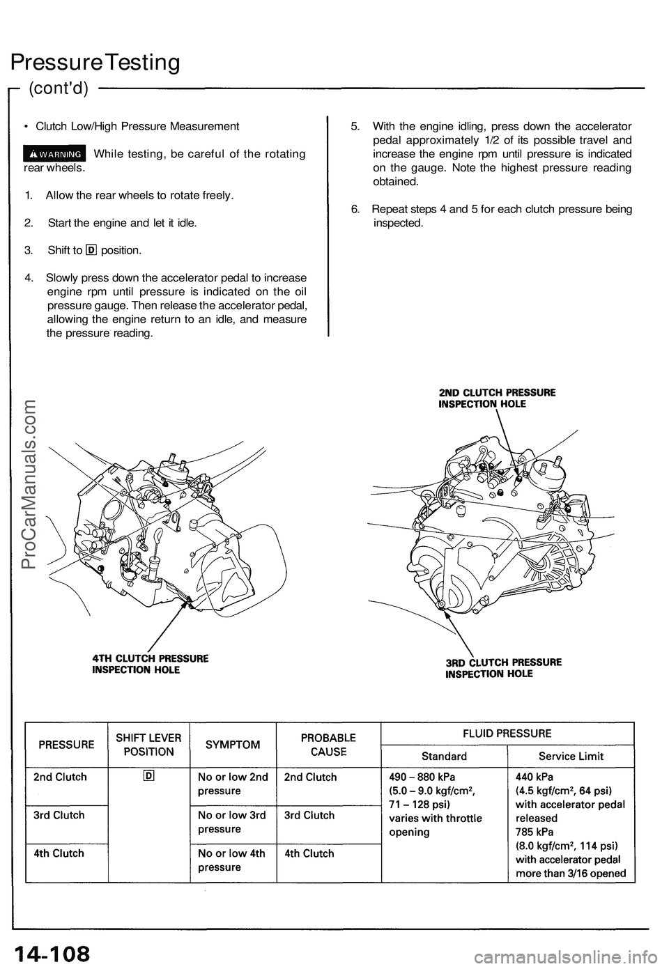
Pressure Testing
• Clutch Low/High Pressure Measurement
While testing, be careful of the rotating
rear wheels.
1. Allow the rear wheels to rotate freely.
2. Start the engine and let it idle.
3. Shift to position.
4. Slowly press down the accelerator pedal to increase
engine rpm until pressure is indicated on the oil
pressure gauge. Then release the accelerator pedal,
allowing the engine return to an idle, and measure
the pressure reading.
5. With the engine idling, press down the accelerator
pedal approximately 1/2 of its possible travel and
increase the engine rpm until pressure is indicated
on the gauge. Note the highest pressure reading
obtained.
6. Repeat steps 4 and 5 for each clutch pressure being
inspected.ProCarManuals.com
Page 1206 of 1503
A/C Servic e Tip s an d Precaution s
The ai r conditionin g syste m use s HFC-134 a (R-134a ) refrigeran t and polyalkyleneglyco l (PAG ) refrigeran t oil*, whic h are
not compatibl e wit h CFC-1 2 (R-12 ) refrigeran t an d minera l oil . D o no t us e R-1 2 refrigeran t o r minera l oi l i n thi s system , an d
d o no t attemp t t o us e R-1 2 servicin g equipment ; damag e t o th e ai r conditionin g syste m o r you r servicin g equipmen t wil l result .
*DENS O ND-OIL8 :
• P/N 3889 9 - PR 7 - A01 : 4 0 ( 1 1/ 3 fl-oz , 1. 4 Imp-oz )
• P/ N 38897-PR7-A01AH : 12 0 ( 4 fl-oz , 4. 2 Imp-oz )
Onl y us e servic e equipmen t tha t i s U.L.-liste d an d i s certifie d t o mee t th e requirement s o f SA E J221 0 t o remov e R-134 a
from th e ai r conditione r system .
CAUTION : Exposur e t o ai r conditione r refrigeran t an d lubrican t vapo r o r mis t ca n irritat e eyes , nos e an d throat , Avoi d
breathin g th e ai r conditione r refrigeran t an d lubrican t vapo r o r mist .
I f accidenta l syste m discharg e occurs , ventilat e wor k are a befor e resumin g service .
R-134 a servic e equipmen t o r vehicl e ai r conditione r system s shoul d no t b e pressur e teste d o r lea k teste d wit h compresse d air .
Som e mixture s o f ai r an d R-134 a hav e bee n show n t o b e combustibl e elevate d pressure s an d ca n resul t
i n fir e o r explosio n causin g injur y o r propert y damage . Neve r us e compresse d ai r t o pressur e tes t R-134 a servic e
equipmen t o r vehicl e ai r conditionin g systems .
Additional healt h an d safet y informatio n ma y b e obtaine d fro m th e refrigeran t an d lubrican t manufacturers .
1. Alway s disconnec t th e negativ e cabl e fro m th e batter y wheneve r replacin g ai r conditionin g parts .
2 . Kee p moistur e an d dus t ou t o f th e system . Whe n disconnectin g an y lines , plu g o r ca p th e fitting s immediately ; don' t
remov e th e cap s o r plug s unti l jus t befor e yo u reconnec t eac h line .
3 . Befor e connectin g an y hos e o r line , appl y a fe w drop s o f refrigeran t oi l t o th e O-ring .
4. Whe n tightenin g o r loosenin g a fitting , us e a secon d wrenc h to suppor t th e matchin g fitting .
5. Whe n recoverin g th e system , us e a R-134 a refrigeran t Recovery/Recycling/Chargin g System ; don' t releas e
refrigeran t int o th e atmosphere .
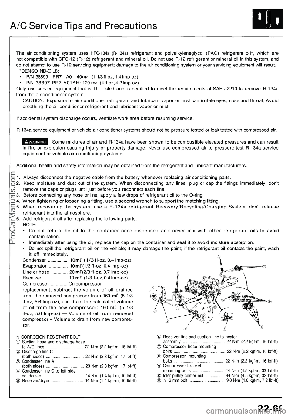
6 . Ad d refrigeran t oi l afte r replacin g th e followin g parts :
NOTE :
• D o no t retur n th e oi l t o th e containe r onc e dispense d an d neve r mi x wit h othe r refrigeran t oil s t o avoi d
contamination .
• Immediatel y afte r usin g th e oil , replac e th e ca p o n th e containe r an d sea l i t t o avoi d moistur e absorption .
• D o no t spil l th e refrigeran t oi l o n th e vehicle ; i t ma y damag e th e paint ; i f th e refrigeran t oi l contact s th e paint , was h
i t of f immediately .
Condense r
............... . 1 0 (1/ 3 fl-oz, 0.4 Imp-oz )
Evaporato r .............. . 1 0 (1/ 3 fl-oz , 0. 4 Imp-oz )
Lin e o r hos e ............ . 2 0 (2/ 3 fl-oz , 0. 7 Imp-oz )
Receive r ................... . 1 0 (1/ 3 fl-oz , 0. 4 Imp-oz )
Compresso r ............ . O n compresso r
replacement , subtrac t th e volum e o f oi l draine d
from th e remove d compresso r fro m 16 0 ( 5 1/ 3
fl-oz , 5. 6 Imp-oz) , an d drai n th e calculate d volum e
of oi l fro m th e ne w compressor : 16 0 ( 5 1/ 3
fl-oz , 5. 6 Imp-oz ) — Volum e o f oi l fro m remove d
compresso r = Volum e t o drai n fro m ne w compres -
sor.
CORROSIO N RESISTAN T BOL T
Suctio n hos e an d discharg e hos e
t o A/ C line s ................................. . 2 2 N- m (2. 2 kgf-m , 1 6 Ibf-ft )
Discharg e lin e C
(bot h sides ) .................................. 23 N- m (2. 3 kgf-m , 1 7 Ibf-ft )
Condense r lin e A
(bot h sides ) ................................. . 2 3 N- m (2. 3 kgf-m , 1 7 Ibf-ft )
Condense r lin e C to lef t sid e
condense r .................................... . 1 4 N- m (1. 4 kgf-m , 1 0 Ibf-ft )
Receiver/drye r ............................ . 1 4 N- m (1. 4 kgf-m , 1 0 Ibf-ft ) Receive
r lin e an d suctio n lin e t o heate r
assembl y ..................................... . 2 2 N- m (2. 2 kgf-m , 1 6 Ibf-ft )
Compresso r hos e mountin g
bolt s ............................................. . 2 2 N- m (2. 2 kgf-m , 1 6 Ibf-ft )
Compresso r mountin g
bolt s ............................................. . 2 2 N- m (2. 2 kgf-m , 1 6 Ibf-ft )
Compresso r bracke t
mountin g bolt s ........................... . 4 4 N- m (4. 5 kgf-m , 3 3 Ibf-ft )
Idle r pulle y cente r nu t ................ . 4 4 N- m (4. 5 kgf-m , 3 3 Ibf-ft )
6 m m bol t ................................ . 9. 8 N- m (1. 0 kgf-m , 7. 2 Ibf-ft )
ProCarManuals.com
Page 1261 of 1503
Description ——————————————————\
——————————————————\
———
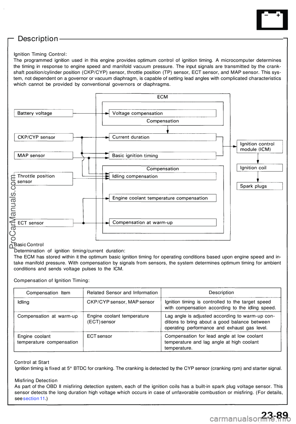
Ignition Timin g Control :
Th e programme d ignitio n use d i n thi s engin e provide s optimu m contro l o f ignitio n timing . A microcompute r determine s
th e timin g i n respons e t o engin e spee d an d manifol d vacuu m pressure . Th e inpu t signal s ar e transmitte d b y th e crank -
shaf t position/cylinde r positio n (CKP/CYP ) sensor , throttl e positio n (TP ) sensor , EC T sensor , an d MA P sensor . Thi s sys -
tem , no t dependen t o n a governo r o r vacuu m diaphragm , i s capabl e o f settin g lea d angle s wit h complicate d characteristic s
whic h canno t b e provide d b y conventiona l governor s o r diaphragms .
Basi c Contro l
Determinatio n of ignitio n timing/curren t duration :
Th e EC M ha s store d withi n i t th e optimu m basi c ignitio n timin g fo r operatin g condition s base d upo n engin e spee d an d in -
tak e manifol d pressure . Wit h compensatio n b y signal s fro m sensors , th e syste m determine s optimu m timin g fo r ambien t
condition s an d send s voltag e pulse s t o th e ICM .
Compensatio n o f Ignitio n Timing :
Compensatio n Ite m
Idlin g
Compensatio n a t warm-u p
Engin e coolan t
temperatur e compensatio nRelate
d Senso r an d Informatio n
CKP/CY P sensor , MA P senso r
Engin e coolan t temperatur e
(ECT) senso r
ECT senso r Descriptio
n
Ignitio n timin g i s controlle d t o th e targe t spee d
wit h compensatio n accordin g t o th e idlin g speed .
La g angl e i s adjuste d accordin g t o warm-u p con -
dition s t o brin g abou t a goo d balanc e betwee n
operatin g performanc e an d exhaus t ga s level .
Compensatio n fo r lea d angl e a t low coolan t
temperatur e an d la g angl e a t hig h coolan t
temperature .
Contro l a t Star t
Ignitio n timin g is fixe d a t 5 ° BTD C fo r cranking . Th e crankin g is detecte d b y th e CY P senso r (crankin g rpm ) an d starte r signal .
Misfirin g Detectio n
A s par t o f th e OB D II misfirin g detectio n system , eac h o f th e ignitio n coil s ha s a built-i n spar k plu g voltag e sensor . Thi s
senso r detect s th e lon g duratio n hig h voltag e whic h occur s i n cas e o f unfavorabl e combustio n o r misfiring . (Fo r details ,
se e sectio n 11 .)
ProCarManuals.com
Page 1284 of 1503
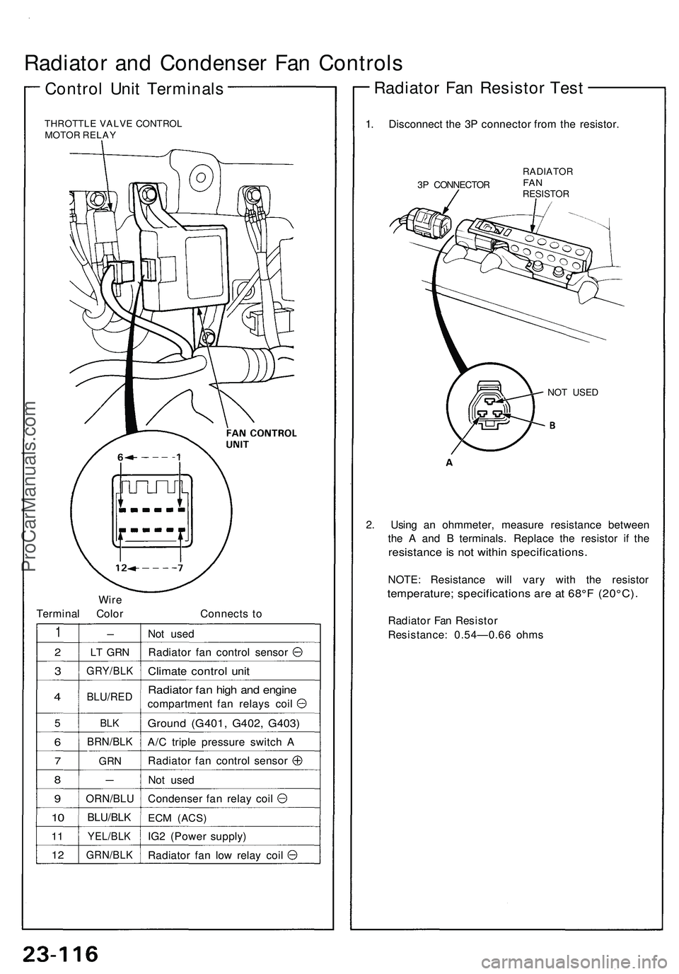
Radiator and Condenser Fan Controls
Control Unit Terminals
THROTTLE VALVE CONTROL
MOTOR RELAY
Wire
Terminal Color
Connects to
1
2
3
4
5
6
7
8
9
10
11
12
-
LT GRN
GRY/BLK
BLU/RED
BLK
BRN/BLK
GRN
—
ORN/BLU
BLU/BLK
YEL/BLK
GRN/BLK
Not used
Radiator fan control sensor
Climate control unit
Radiator fan high and engine
compartment fan relays coil
Ground (G401, G402, G403)
A/C triple pressure switch A
Radiator fan control sensor
Not used
Condenser fan relay coil
ECM
(ACS)
IG2 (Power supply)
Radiator fan low relay coil
1. Disconnect the 3P connector from the resistor.
3P CONNECTOR
RADIATOR
FAN
RESISTOR
NOT USED
2. Using an ohmmeter, measure resistance between
the A and B terminals. Replace the resistor if the
resistance is not within specifications.
NOTE: Resistance will vary with the resistor
temperature; specifications are at 68°F (20°C).
Radiator Fan Resistor
Resistance: 0.54—0.66 ohms
Radiator Fan Resistor TestProCarManuals.com
Page 1292 of 1503
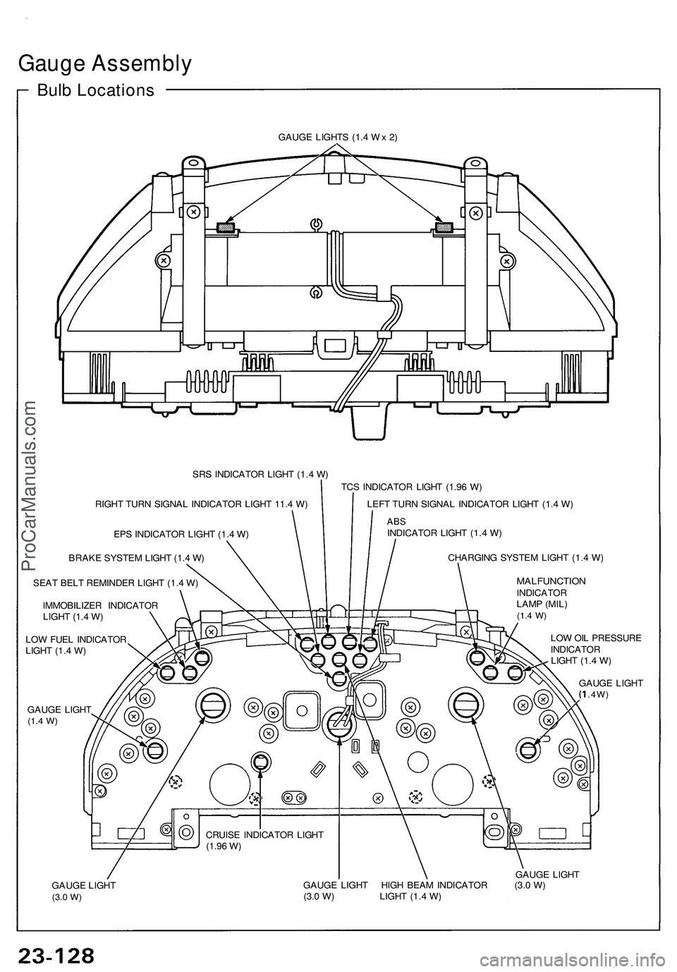
Gauge Assembly
Bulb Locations
GAUGE LIGHTS (1.4 Wx 2)
SRS INDICATOR LIGHT (1.4 W)
RIGHT TURN SIGNAL INDICATOR LIGHT 11.4 W)
EPS INDICATOR LIGHT (1.4 W)
BRAKE SYSTEM LIGHT (1.4 W)
SEAT BELT REMINDER LIGHT (1.4 W)
IMMOBILIZER INDICATOR
LIGHT (1.4 W)
LOW FUEL INDICATOR
LIGHT (1.4 W)
GAUGE LIGHT
(1.4
W)
TCS INDICATOR LIGHT (1.96 W)
LEFT TURN SIGNAL INDICATOR LIGHT (1.4 W)
ABS
INDICATOR LIGHT (1.4 W)
CHARGING SYSTEM LIGHT (1.4 W)
MALFUNCTION
INDICATOR
LAMP (MIL)
(1.4
W)
CRUISE INDICATOR LIGHT
(1.96
W)
LOW OIL PRESSURE
INDICATOR
LIGHT (1.4 W)
GAUGE LIGHT
.4W)
GAUGE LIGHT
(3.0
W)
GAUGE LIGHT
GAUGE LIGHT HIGH BEAM INDICATOR (3.0 W)
(3.0 W) LIGHT (1.4 W)ProCarManuals.com
Page 1323 of 1503
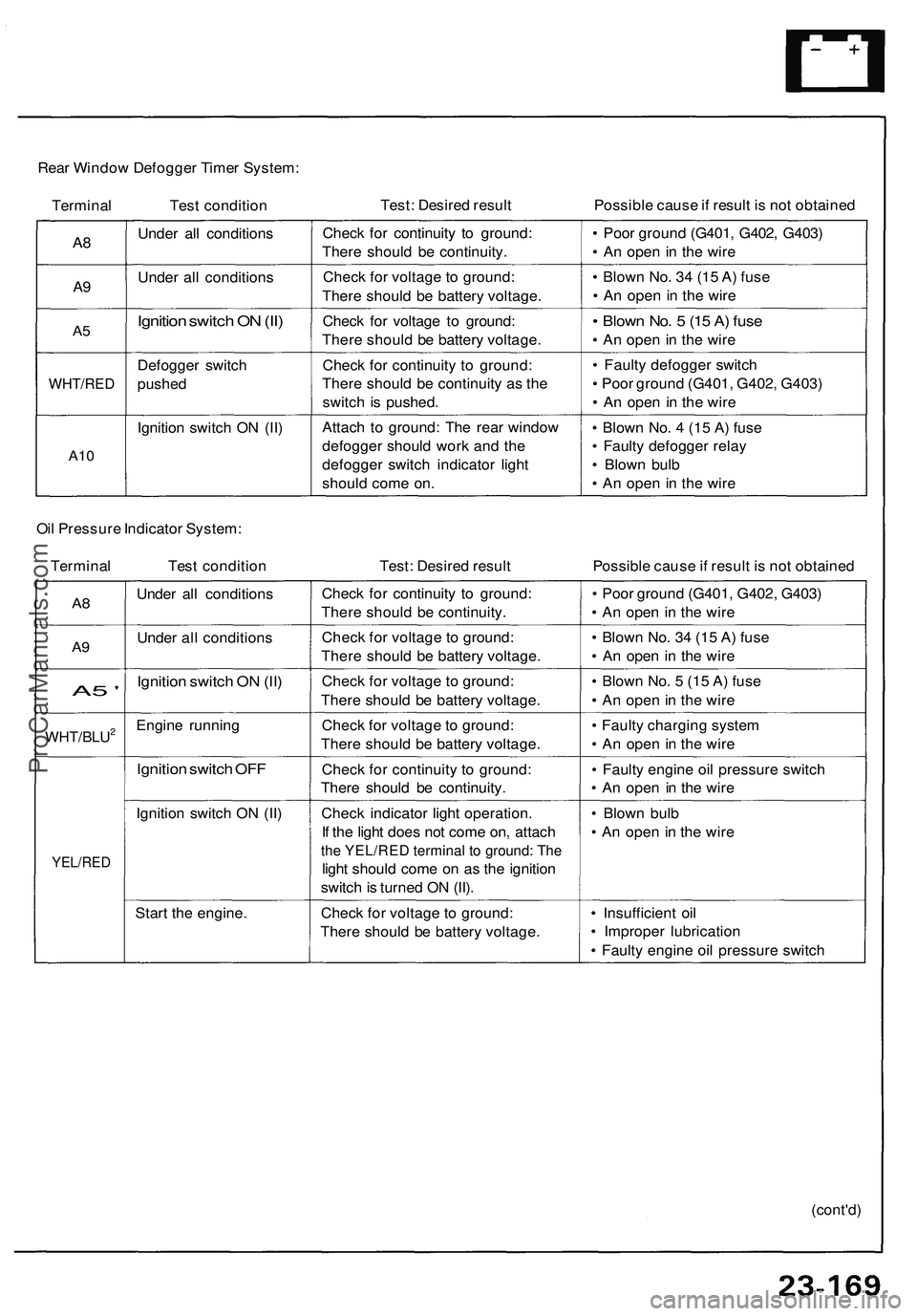
Rear Window Defogger Timer System:
Terminal Test condition
Test: Desired result
Possible cause if result is not obtained
A8
A9
A5
WHT/RED
A10
Under all conditions
Under all conditions
Ignition switch ON (II)
Defogger switch
pushed
Ignition switch ON (II)
Check for continuity to ground:
There should be continuity.
Check for voltage to ground:
There should be battery voltage.
Check for voltage to ground:
There should be battery voltage.
Check for continuity to ground:
There should be continuity as the
switch is pushed.
Attach to ground: The rear window
defogger should work and the
defogger switch indicator light
should come on.
• Poor ground (G401, G402, G403)
• An open in the wire
• Blown No. 34 (15 A) fuse
• An open in the wire
• Blown No. 5 (15 A) fuse
• An open in the wire
• Faulty defogger switch
• Poor ground (G401, G402, G403)
• An open in the wire
• Blown No. 4 (15 A) fuse
• Faulty defogger relay
• Blown bulb
• An open in the wire
Oil Pressure Indicator System:
Terminal Test condition
Test: Desired result
Possible cause if result is not obtained
A8
A9
A5 '
WHT/BLU2
YEL/RED
Under all conditions
Under all conditions
Ignition switch ON (II)
Engine running
Ignition switch OFF
Ignition switch ON (II)
Start the engine.
Check for continuity to ground:
There should be continuity.
Check for voltage to ground:
There should be battery voltage.
Check for voltage to ground:
There should be battery voltage.
Check for voltage to ground:
There should be battery voltage.
Check for continuity to ground:
There should be continuity.
Check indicator light operation.
If the light does not come on, attach
the YEL/RED terminal to ground: The
light should come on as the ignition
switch is turned ON (II).
Check for voltage to ground:
There should be battery voltage.
• Poor ground (G401, G402, G403)
• An open in the wire
• Blown No. 34 (15 A) fuse
• An open in the wire
• Blown No. 5 (15 A) fuse
• An open in the wire
• Faulty charging system
• An open in the wire
• Faulty engine oil pressure switch
• An open in the wire
• Blown bulb
• An open in the wire
• Insufficient oil
• Improper lubrication
• Faulty engine oil pressure switch
(cont'd)ProCarManuals.com