check engine ACURA NSX 1997 Service Repair Manual
[x] Cancel search | Manufacturer: ACURA, Model Year: 1997, Model line: NSX, Model: ACURA NSX 1997Pages: 1503, PDF Size: 57.08 MB
Page 32 of 1503
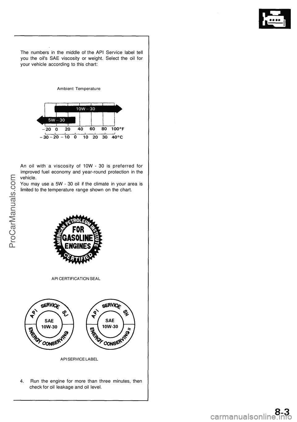
The numbers in the middle of the API Service label tell
you the oil's SAE viscosity or weight. Select the oil for
your vehicle according to this chart:
Ambient Temperature
An oil with a viscosity of 10W - 30 is preferred for
improved fuel economy and year-round protection in the
vehicle.
You may use a 5W - 30 oil if the climate in your area is
limited to the temperature range shown on the chart.
API CERTIFICATION SEAL
API SERVICE LABEL
4. Run the engine for more than three minutes, then
check for oil leakage and oil level.ProCarManuals.com
Page 141 of 1503
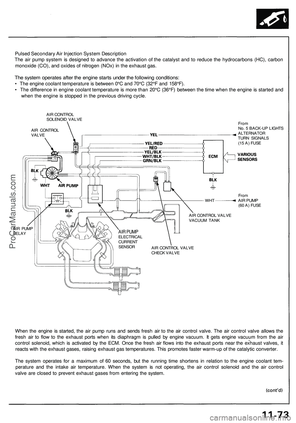
Pulsed Secondary Air Injection System Description
The air pump system is designed to advance the activation of the catalyst and to reduce the hydrocarbons (HC), carbon
monoxide (CO), and oxides of nitrogen (NOx) in the exhaust gas.
The system operates after the engine starts under the following conditions:
• The engine coolant temperature is between 0°C and 70°C (32°F and 158°F).
• The difference in engine coolant temperature is more than 20°C (36°F) between the time when the engine is started and
when the engine is stopped in the previous driving cycle.
AIR CONTROL
SOLENOID VALVE
AIR CONTROL
VALVE
WHT
AIR PUMP
RELAY
From
No. 5 BACK-UP LIGHTS
ALTERNATOR
TURN SIGNALS
(15 A) FUSE
From
AIR PUMP
(60 A) FUSE
AIR CONTROL VALVE
VACUUM TANK
AIR CONTROL VALVE
CHECK VALVE
When the engine is started, the air pump runs and sends fresh air to the air control valve. The air control valve allows the
fresh air to flow to the exhaust ports when its diaphragm is pulled by engine vacuum. It gets engine vacuum from the air
control solenoid, which is activated by the ECM. Once the fresh air flows into the exhaust ports near the exhaust valves, it
reacts with the exhaust gases, raising exhaust gas temperatures. This promotes faster warm-up of the catalytic converter.
The system operates for a maximum of 60 seconds, but the running time shortens in relation to the engine coolant tem-
perature and the intake air temperature. When the system is not operating, the air control solenoid and the air control
valve are closed to prevent exhaust gases from entering the system.
AIR PUMP
ELECTRICAL
CURRENT
SENSORProCarManuals.com
Page 349 of 1503
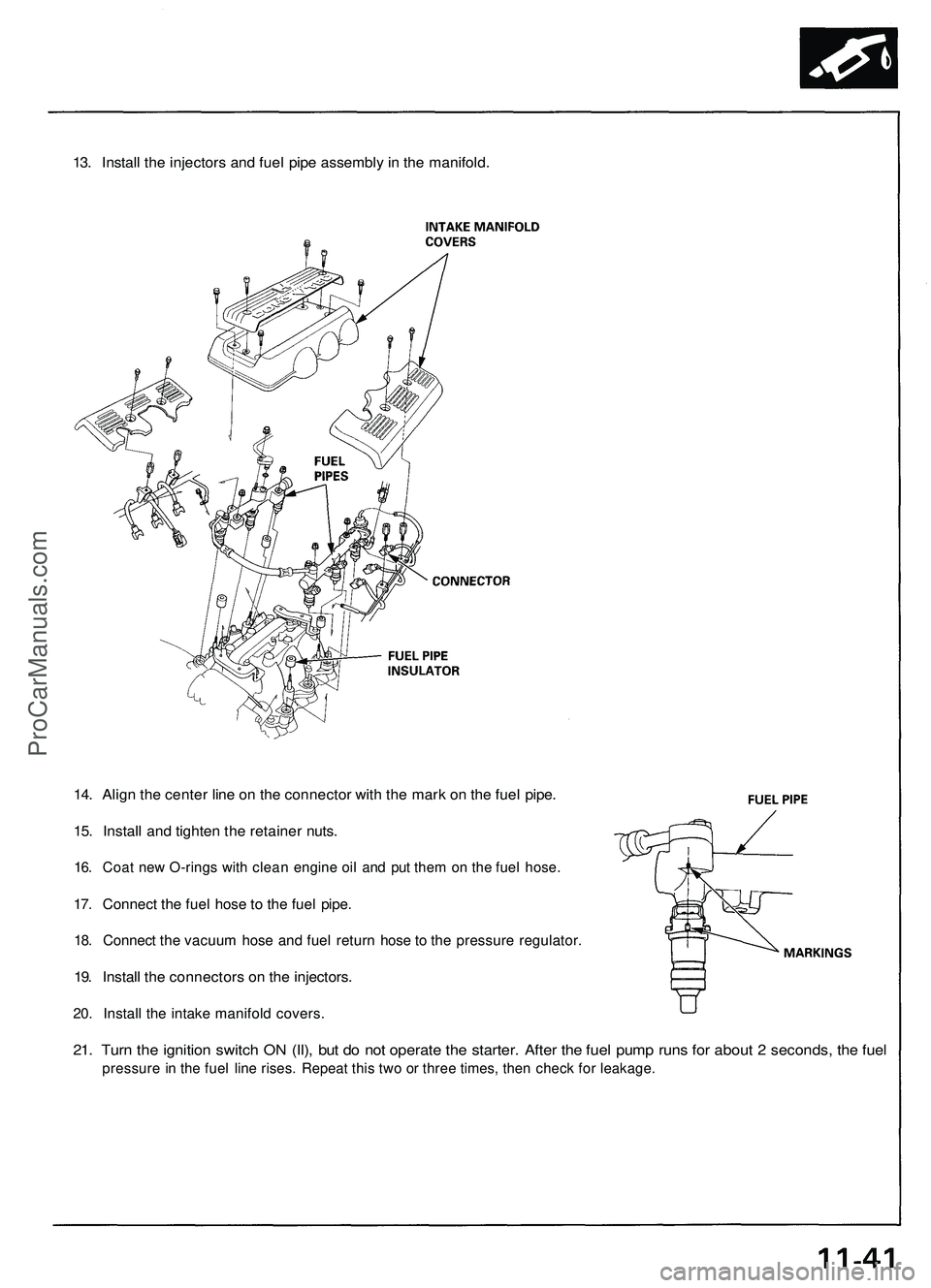
13. Install the injectors and fuel pipe assembly in the manifold.
14. Align the center line on the connector with the mark on the fuel pipe.
15. Install and tighten the retainer nuts.
16. Coat new O-rings with clean engine oil and put them on the fuel hose.
17. Connect the fuel hose to the fuel pipe.
18. Connect the vacuum hose and fuel return hose to the pressure regulator.
19. Install the connectors on the injectors.
20. Install the intake manifold covers.
21. Turn the ignition switch ON (II), but do not operate the starter. After the fuel pump runs for about 2 seconds, the fuel
pressure in the fuel line rises. Repeat this two or three times, then check for leakage.ProCarManuals.com
Page 364 of 1503
1-2
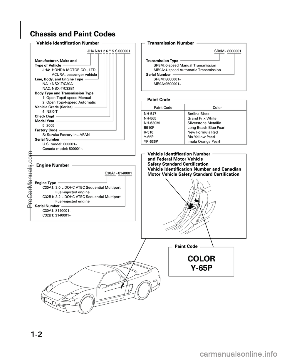
Chassis and Paint Codes
Manufacturer, Make and
Type of Vehicle
JH4: HONDA MOTOR CO., LTD.ACURA, passenger vehicle
Line, Body, and Engine Type
NA1: NSX-T/C30A1
NA2: NSX-T/C32B1
Body Type and Transmission Type
1: Open Top/6-speed Manual
2: Open Top/4-speed Automatic
Vehicle Grade (Series)
6: NSX-T
Check Digit
Model Year
5: 2005
Factory Code
S: Suzuka Factory in JAPAN
Serial Number
U.S. model: 000001~
Canada model: 800001~
Vehicle Identification Number
000001S5*62NA1JH4
Engine Type
C30A1: 3.0 L DOHC VTEC Sequential Multiport Fuel-injected engine
C32B1: 3.2 L DOHC VTEC Sequential Multiport Fuel-injected engine
Serial Number
C30A1: 8140001~
C32B1: 3140001~
Engine Number
8140001-C30A1
Transmission Type
SR8M: 6-speed Manual Transmission
MR9A: 4-speed Automatic Transmission
Serial Number
SR8M: 8000001~
MR9A: 9500001~
Transmission Number
8000001-SR8M
Paint Code
Paint Code Color
NH-547 Berlina Black
NH-565 Grand Prix White
NH-630M Silverstone Metallic
B510P Long Beach Blue Pearl
R-510 New Formula Red
Y-65P
YR-536P
Paint Code
Vehicle Identification Number
Safety Standard Certification
Vehicle Identification Number and Canadian
Motor Vehicle Safety Standard Certification
COLOR Y-65P
*03-NSX (61SW004)SEC01(01-04) 9/22/04 1:48 PM Page 1-2
Rio Yellow Pearl
and Federal Motor Vehicle
Imola Orange Pearl
ProCarManuals.com
Page 367 of 1503
3-2
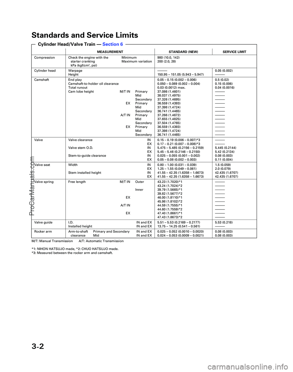
Standards and Service Limits
MEASUREMENTSTANDARD (NEW)SERVICE LIMIT
CompressionCheck the engine with the Minimumstarter cranking Maximum variation
kPa (kgf/cm
2, psi)
980 (10.0, 142)
200 (2.0, 28)
Cylinder headWarpage
Height—150.95 – 151.05 (5.943 – 5.947)0.05 (0.002)—
CamshaftEnd play
Camshaft-to-holder oil clearance
Total runout
Cam lobe height M/T IN Primary Mid
Secondary
EX Primary Mid
Secondary
A/T IN Primary Mid
Secondary
EX Primary Mid
Secondary0.05 – 0.15 (0.002 – 0.006)
0.050 – 0.089 (0.002 – 0.004)
0.03 (0.0012) max.
37.086 (1.4601)
38.037 (1.4975)
37.326 (1.4695)
36.559 (1.4393)
37.398 (1.4724)
36.741 (1.4465)
37.266 (1.4672)
37.655 (1.4825)
37.504 (1.4765)
36.559 (1.4393)
37.398 (1.4724)
36.741 (1.4465)0.5 (0.02)
0.15 (0.006)
0.04 (0.0016)
—
—
—
—
—
—
—
—
—
—
—
—
ValveValve clearance IN EX
Valve stem O.D. IN EX
Stem-to-guide clearance IN EX0.15 – 0.19 (0.006 – 0.007)*3
0.17 – 0.21 (0.007 – 0.008)*3
5.475 – 5.485 (0.2156 – 0.2159)
5.45 – 5.46 (0.2146 – 0.2150)
0.025 – 0.055 (0.001 – 0.002)
0.05 – 0.08 (0.002 – 0.003)—
—
5.445 (0.2144)
5.42 (0.2134)
0.08 (0.003)
0.11 (0.004)
Valve seatWidth INEX
Stem installed height IN EX0.80 – 1.00 (0.031 – 0.039)
1.25 – 1.55 (0.049 – 0.061)
41.55 – 42.35 (1.6358 – 1.6673)
41.55 – 42.35 (1.6358 – 1.6673)1.5 (0.059)
2.0 (0.079)
42.435 (1.6707)
42.435 (1.6707)
Valve springFree length M/T IN Outer
Inner
EX
A/T IN EX43.23 (1.7020)*1
43.24 (1.7024)*2
39.79 (1.5665)*1
39.82 (1.5677)*2
46.00 (1.8110)*1
45.98 (1.8102)*2
44.59 (1.7555)*1
44.60 (1.7559)*2
47.40 (1.8661)*1
47.43 (1.8673)*2—
—
—
—
—
—
—
—
—
—
Valve guideI.D. IN and EX
Installed height IN and EX5.51 – 5.53 (0.2169 – 0.2177)
13.75 – 14.25 (0.541 – 0.561)5.53 (0.218)—
Rocker armArm-to-shaft Primary and Secondary IN and EXclearance Mid IN and EX0.025 – 0.052 (0.0010 – 0.0020)
0.024 – 0.053 (0.0009 – 0.0021)0.08 (0.003)
0.08 (0.003)
M/T: Manual Transmission A/T: Automatic Transmission
*1: NIHON HATSUJO made, *2: CHUO HATSUJO made.
*3: Measured between the rocker arm and camshaft.
Cylinder Head/Valve Train — Section 6
*04-NSX (61SW004)SEC03(01-16) 9/22/04 1:48 PM Page 3-2
ProCarManuals.com
Page 374 of 1503
4-5
Y
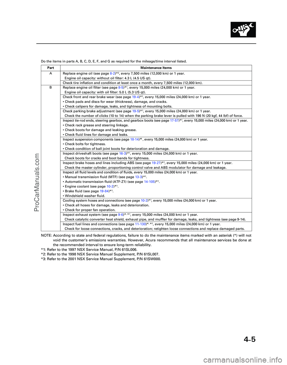
Do the items in parts A, B, C, D, E, F, and G as required for the mileag\
e/time interval listed.
NOTE: According to state and federal regulations, failure to do the maintenanc\
e items marked with an asterisk (*) will not
void the customer ’s emissions warranties. However, Acura recommends that all maintenance s\
ervices be done at
the recommended interval to ensure long-term reliability.
*1: Refer to the 1997 NSX Service Manual, P/N 61SL006.
*2: Refer to the 1998 NSX Service Manual Supplement, P/N 61SL007.
*3: Refer to the 2001 NSX Service Manual Supplement, P/N 61SW000.
A
B Replace engine oil (see page
8-2)*
2, every 7,500 miles (12,000 km) or 1 year.
Engine oil capacity: without oil filter: 4.3 L (4.5 US qt).
Check tire inflation and condition at least once a month, every 7,500 mi\
les (12,000 km).
Replace engine oil filter (see page 8-5)*1, every 15,000 miles (24,000 km) or 1 year.
Engine oil capacity: with oil filter: 5.0 L (5.3 US qt).
Check front and rear brake wear (see page 19-4)*1, every 15,000 miles (24,000 km) or 1 year.
• Check pads and discs for wear (thickness), damage, and cracks.
• Check calipers for damage, leaks, and tightness of mounting bolts.
Check parking brake adjustment (see page 19-5)*1, every 15,000 miles (24,000 km) or 1 year.
Check the number of clicks (10 to 14) when the parking brake lever is pulled with 196 N (20 kgf,\
44 lbf) of force.
Inspect tie-rod ends, steering gearbox, and gearbox boots (see page 17-57)*1, every 15,000 miles (24,000 km) or 1 year.
• Check rack grease and steering linkage.
• Check boots for damage and leaking grease.
• Check fluid lines for damage and leaks.1
• Check bolts for tightness.
• Check condition of ball joint boots for deterioration and damage.
Inspect driveshaft boots (see page 16-3)*1, every 15,000 miles (24,000 km) or 1 year.
Check boots for cracks and boot bands for tightness.
Inspect brake hoses and lines including ABS (see page 19-27)*1, every 15,000 miles (24,000 km) or 1 year.
Check the master cylinder, proportioning control valve and ABS modulator\
for damage and leakage.
Inspect all fluid levels and condition of fluids, every 15,000 miles (2\
4,000 km) or 1 year.
• Manual transmission fluid (MTF) (see page 13-3)*
1.
• Automatic transmission fluid (ATF-Z1) (see page 14-105)*1.
• Engine coolant (see page 10-2)*1.
• Brake fluid (see page 19-84)*1.
• Windshield washer fluid.
Cooling system hoses and connections (see page 10-2)*1, every 15,000 miles (24,000 km) or 1 year.
• Check all hoses for damage, leaks and deterioration.
• Check for proper fan operation.
Inspect exhaust system (see page 9-6)*, *1, every 15,000 miles (24,000 km) or 1 year.
Check catalytic converter heat shield, exhaust pipe, and muffler for dam\
age, leaks, and tightness ( see page 9-14 ).
Inspect fuel lines and connections (see page 11-130)*, *1, every 15,000 miles (24,000 km) or 1 year.
Check for loose connections, cracks, and deterioration; retighten loose \
connections and replace damaged parts.
Part Maintenance Items
*05-NSX (61SW004)SEC04(01-10) 9/22/04 1:49 PM Page 4-5
Inspect suspension components (see page 18-14)* , every 15,000 miles (24,000 km) or 1 year.
ProCarManuals.com
Page 375 of 1503
4-6
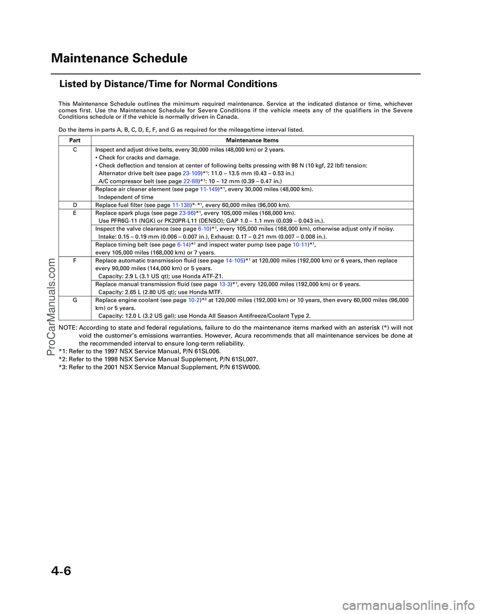
This Maintenance Schedule outlines the minimum required maintenance. Ser\
vice at the indicated distance or time, whichever
comes first. Use the Maintenance Schedule for Severe Conditions if the v\
ehicle meets any of the qualifiers in the Severe
Conditions schedule or if the vehicle is normally driven in Canada.
Do the items in parts A, B, C, D, E, F, and G as required for the mileag\
e/time interval listed.
NOTE: According to state and federal regulations, failure to do the maintenanc\
e items marked with an asterisk (*) will not
void the customer ’s emissions warranties. However, Acura recommends that all maintenance s\
ervices be done at
the recommended interval to ensure long-term reliability.
*1: Refer to the 1997 NSX Service Manual, P/N 61SL006.
*2: Refer to the 1998 NSX Service Manual Supplement, P/N 61SL007.
*3: Refer to the 2001 NSX Service Manual Supplement, P/N 61SW000.
C
D
E
F
G Inspect and adjust drive belts, every 30,000 miles (48,000 km) or 2 ye\
ars.
•
Check for cracks and damage.
• Check deflection and tension at center of following belts pressing with\
98 N (10 kgf, 22 lbf) tension:
Alternator drive belt (see page 23-109)*
1: 11.0 – 13.5 mm (0.43 – 0.53 in.)
A/C compressor belt (see page 22-88)*1: 10 – 12 mm (0.39 – 0.47 in.)
Replace air cleaner element (see page 11-149)*1, every 30,000 miles (48,000 km).
Independent of time
Replace fuel filter (see page 11-138)*, *1, every 60,000 miles (96,000 km).
Replace spark plugs (see page 23-96)*1, every 105,000 miles (168,000 km).
Use PFR6G-11 (NGK) or PK20PR-L11 (DENSO); GAP 1.0 – 1.1 mm (0.039 – 0.043 in.).
Inspect the valve clearance (see page 6-10)*1, every 105,000 miles (168,000 km), otherwise adjust only if noisy.
Intake: 0.15 – 0.19 mm (0.006 – 0.007 in.), Exhaust: 0.17 – 0.21 mm (0.007 – 0.008 in.).
Replace timing belt (see page 6-14)*1 and inspect water pump (see page 10-11)*1,
every 105,000 miles (168,000 km) or 7 years.
Replace automatic transmission fluid (see page 14-105)*1 at 120,000 miles (192,000 km) or 6 years, then replace
every 90,000 miles (144,000 km) or 5 years.
Capacity: 2.9 L (3.1 US qt); use Honda ATF-Z1.
Replace manual transmission fluid (see page 13-3)*1, every 120,000 miles (192,000 km) or 6 years.
Capacity: 2.65 L (2.80 US qt); use Honda MTF.
Replace engine coolant (see page 10-2 )*3 at 120,000 miles (192,000 km) or 10 years, then every 60,000 miles (9\
6,000
km) or 5 years. Capacity: 12.0 L (3.2 US gal); use Honda All Season Antifreeze/Coolant\
Type 2.
Part Maintenance Items
Maintenance Schedule
Listed by Distance/Time for Normal Conditions
*05-NSX (61SW004)SEC04(01-10) 9/22/04 1:49 PM Page 4-6
ProCarManuals.com
Page 416 of 1503
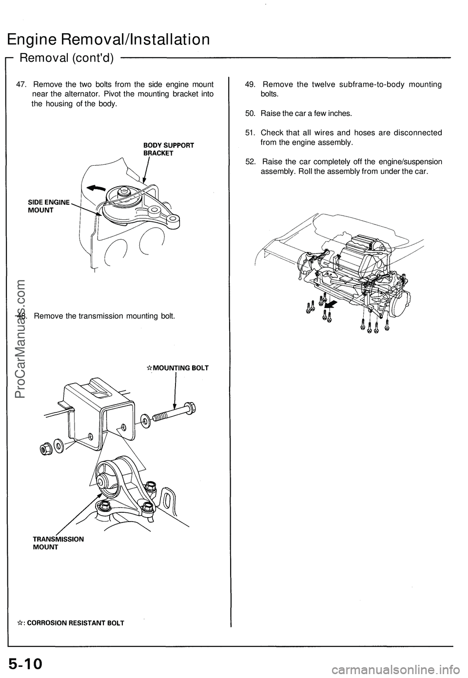
Removal (cont'd)
Engine Removal/Installation
47. Remove the two bolts from the side engine mount
near the alternator. Pivot the mounting bracket into
the housing of the body.
49. Remove the twelve subframe-to-body mounting
bolts.
50. Raise the car a few inches.
51. Check that all wires and hoses are disconnected
from the engine assembly.
52. Raise the car completely off the engine/suspension
assembly. Roll the assembly from under the car.
48. Remove the transmission mounting bolt.ProCarManuals.com
Page 422 of 1503
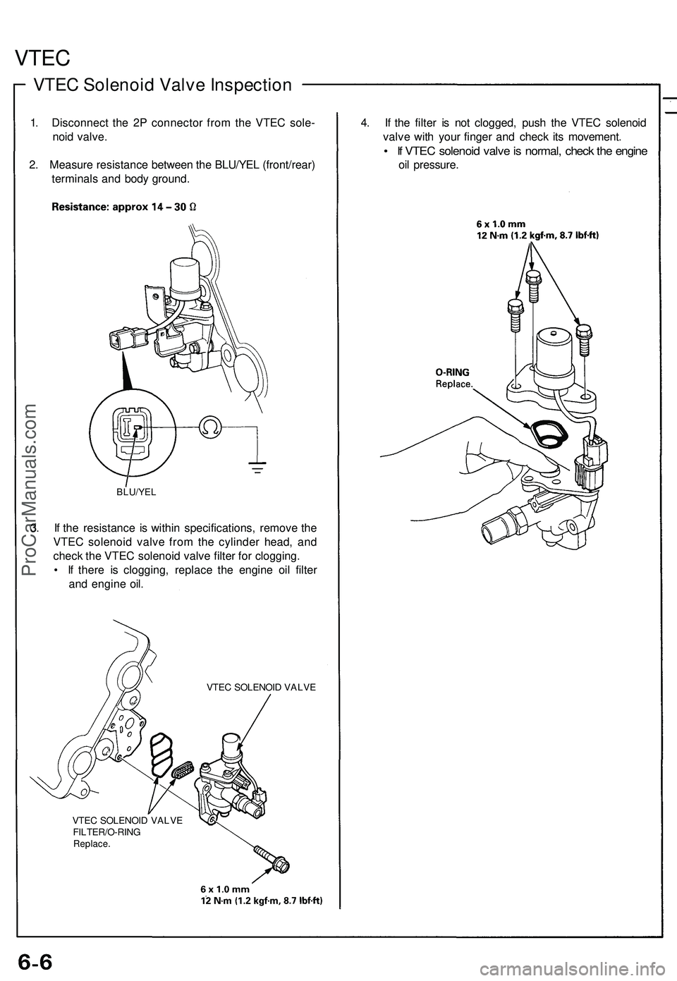
VTEC
VTEC Solenoid Valve Inspection
1. Disconnect the 2P connector from the VTEC sole-
noid valve.
2. Measure resistance between the BLU/YEL (front/rear)
terminals and body ground.
BLU/YEL
3. If the resistance is within specifications, remove the
VTEC solenoid valve from the cylinder head, and
check the VTEC solenoid valve filter for clogging.
• If there is clogging, replace the engine oil filter
and engine oil.
VTEC SOLENOID VALVE
VTEC SOLENOID VALVE
FILTER/O-RING
Replace.
4. If the filter is not clogged, push the VTEC solenoid
valve with your finger and check its movement.
• If VTEC solenoid valve is normal, check the engine
oil pressure.ProCarManuals.com
Page 472 of 1503
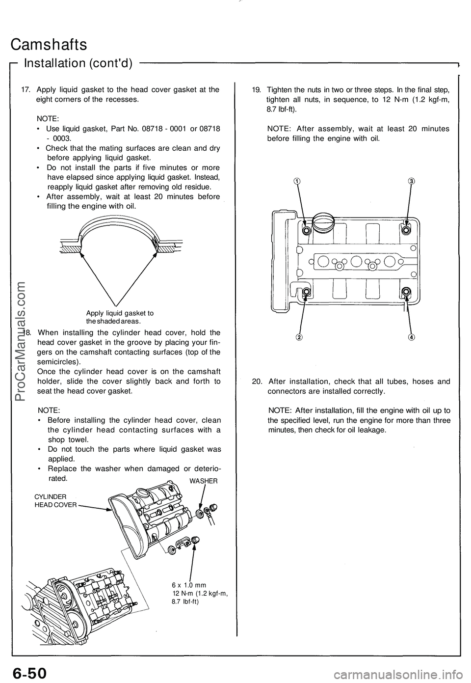
Camshafts
Installation (cont'd)
17. Apply liquid gasket to the head cover gasket at the
eight corners of the recesses.
NOTE:
• Use liquid gasket, Part No. 08718 - 0001 or 08718
- 0003.
• Check that the mating surfaces are clean and dry
before applying liquid gasket.
• Do not install the parts if five minutes or more
have elapsed since applying liquid gasket. Instead,
reapply liquid gasket after removing old residue.
• After assembly, wait at least 20 minutes before
filling the engine with oil.
Apply liquid gasket to
the shaded areas.
18. When installing the cylinder head cover, hold the
head cover gasket in the groove by placing your fin-
gers on the camshaft contacting surfaces (top of the
semicircles).
Once the cylinder head cover is on the camshaft
holder, slide the cover slightly back and forth to
seat the head cover gasket.
NOTE:
• Before installing the cylinder head cover, clean
the cylinder head contacting surfaces with a
shop towel.
• Do not touch the parts where liquid gasket was
applied.
• Replace the washer when damaged or deterio-
rated.
CYLINDER
HEAD COVER
WASHER
6 x 1.0 mm
12 N-m (1.2 kgf-m,
8.7 Ibf-ft)
19. Tighten the nuts in two or three steps. In the final step,
tighten all nuts, in sequence, to 12 N-m (1.2 kgf-m,
8.7 Ibf-ft).
NOTE: After assembly, wait at least 20 minutes
before filling the engine with oil.
20. After installation, check that all tubes, hoses and
connectors are installed correctly.
NOTE: After installation, fill the engine with oil up to
the specified level, run the engine for more than three
minutes, then check for oil leakage.ProCarManuals.com