ACURA RL KA9 1996 Service Repair Manual
Manufacturer: ACURA, Model Year: 1996, Model line: RL KA9, Model: ACURA RL KA9 1996Pages: 1954, PDF Size: 61.44 MB
Page 131 of 1954
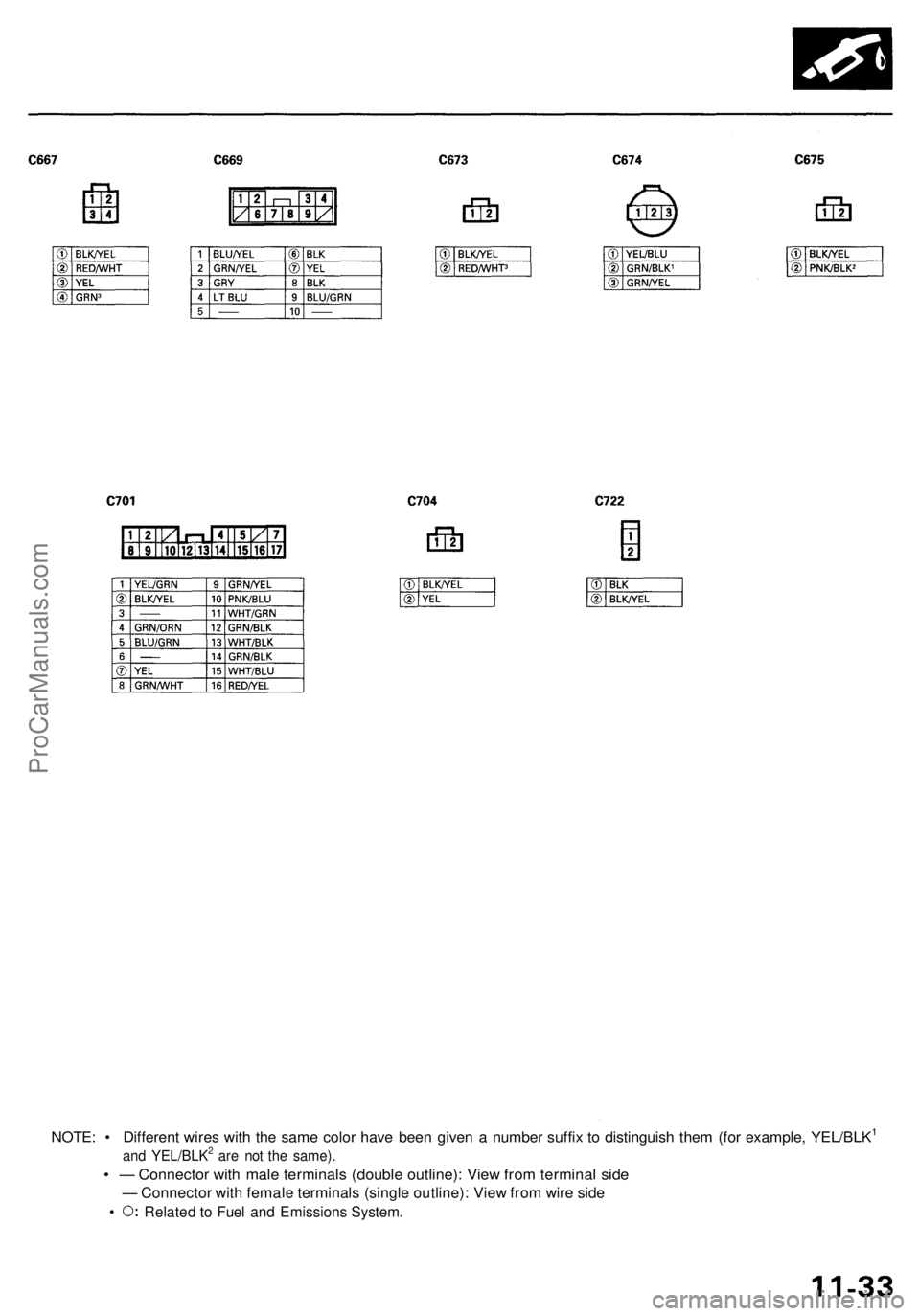
NOTE: • Different wires with the same color have been given a number suffix to distinguish them (for example, YEL/BLK1
and YEL/BLK2 are not the same).
• — Connector with male terminals (double outline): View from terminal side
— Connector with female terminals (single outline): View from wire side
• Related to Fuel and Emissions System.ProCarManuals.com
Page 132 of 1954
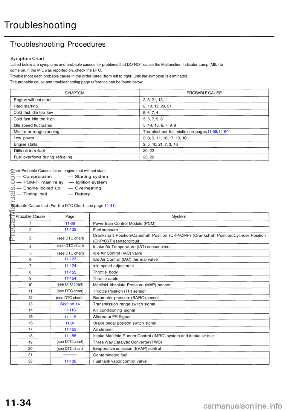
Troubleshooting
Troubleshooting Procedure s
Symptom Char t
Listed below are symptoms and probable causes for problems that DO NOT cause the Malfunction Indicator Lamp (MIL) to
come on. If the MIL was reported on, check the DTC.
Troubleshoot each probable cause in the order listed (from left to right) until the symptom is eliminated.
The probable cause and troubleshooting page reference can be found below.
SYMPTO M
Engine wil l no t star t
Hard startin g
Col d fas t idl e to o lo w
Col d fas t idl e to o hig h
Idl e spee d fluctuate s
Misfire o r roug h runnin g
Low powe r
Engin e stall s
Difficul t t o refue l
Fuel overflow s durin g refuelin g PROBABL
E CAUS E
2, 3 , 21 , 13 , 1
2 , 10 , 12 , 20 , 2 1
5, 6 , 7 , 4
5 , 6 , 7 , 9 , 8
5 , 14 , 15 , 6 , 7 , 9 , 8
Troubleshoo t fo r misfir e o n page
s 11-59 , 11-60
2 , 8 , 9 , 11 , 18,17 , 19 , 1 0
2, 5 , 10 , 21 , 7 , 3 , 1 6
20 , 2 2
20 , 2 2
Other Probable Causes for an engine that will not start:
— Compressio n — Starting syste m
— PGM-F I mai n rela y — Ignitio n syste m
— Engin e locke d u p — Overheatin g
— Timin g bel t — Battery
Probable Caus e
1
2
3
4
5
6
7
8
9
10
1 1
1 2
13
1 4
15
1 6
17
1 8
1 9
2 0
2 1
22
Pag e
11-6 6
(see DTC chart)
(see DTC chart)
(see DTC chart)
Sectio n 1 4
11-8 1
(see DTC chart)
11-10 6
System
Powertrai n Contro l Modul e (PCM )
Fue l pressur e
Crankshaf t Position/Camshaf t Positio n (CKP/CMP ) (Crankshaf t Position/Cylinde r Positio n
(CKP/CYP) ) senso r circui t
Intak e Ai r Temperatur e (IAT ) senso r circui t
Idl e Ai r Contro l (IAC ) valv e
Idl e Ai r Contro l (IAC ) therma l valv e
Idl e spee d adjustmen t
Throttl e bod y
Throttl e cabl e
Manifol d Absolut e Pressur e (MAP ) senso r
Throttl e Positio n (TP ) senso r
Barometri c pressur e (BARO ) senso r
Transmissio n rang e switc h signa l
Ai r conditionin g signa l
Alternato r F R Signa l
Brake peda l positio n switc h signa l
Ai r cleane r
Intak e Manifol d Runne r Contro l (IMRC ) syste m an d intak e ai r duc t
Thre e Wa y Catalyti c Converte r (TWC )
Evaporativ e emissio n (EVAP ) contro l
Contaminate d fue l
Fue l tan k vapo r contro l valv e
Probable Cause List (For the DTC Chart, see page 11-41)
(see DTC chart)
(see DTC chart)
(see DTC chart)
(see DTC chart)
11- 132
11- 123
11- 124
11- 155
11- 154
11- 116
11- 118
11- 155
11- 158
ProCarManuals.com
Page 133 of 1954

Diagnostic Troubl e Cod e (DTC ) Char t
DTC(MIL indication*1)
P010 7 (3 )
P0108 (3 )
P0112 (10 )
P011 3 (10 )
P0116 (86)*2
P011 7 (6 )
P0118 (6 )
P0122 (7 )
P0123 (7 )
P012 5 (86)*
2
P013 3 (62)*2
P013 4 (2 )
P013 5 (42 )
P013 7 (63)*
2
P013 8 (63)*2
Detectio n Ite m
Manifol d Absolut e Pressur e (MAP )
Senso r Circui t Lo w Voltag e
Manifol d Absolut e Pressur e (MAP )
Senso r Circui t Hig h Voltag e
Intak e Ai r Temperatur e (IAT ) Senso r
Circui t Lo w Voltag e
Intak e Ai r Temperatur e (IAT ) Senso r
Circui t Hig h Voltag e
Engine Coolan t Temperatur e (ECT )Senso r Range/Performanc e
Proble m
Engin e Coolan t Temperatur e (ECT )
Senso r Circui t Lo w Voltag e
Engin e Coolan t Temperatur e (ECT )
Senso r Circui t Hig h Voltag e
Throttl e Positio n (TP ) Senso r Circui t
Lo w Voltag e
Throttl e Positio n (TP ) Senso r Circui t
Hig h Voltag e
Engine Coolan t Temperatur e (ECT )Senso r Slo w Respons e
Righ t Primar y Heate d Oxyge n
Senso r (Righ t Primar y H02S ) Slo w
Respons e (Ban k 1 , Senso r 1 )
Righ t Primar y Heate d Oxyge n
Senso r (Righ t Primar y HO2S ) Heate r
Syste m Malfunctio n
Righ t Primar y Heate d Oxyge n
Senso r (Righ t Primar y H02S ) Heate r
Circui t Malfunctio n (Ban k 1 ,
Senso r 1 )
Secondar y Heate d Oxyge n Senso r
(Secondar y H02S ) Circui t Lo w
Voltag e (Senso r 2 )
Secondar y Heate d Oxyge n Senso r
(Secondar y H02S ) Circui t Hig h
Voltag e (Senso r 2 ) Probabl
e Caus e
• Ope n o r shor t i n MA P senso r circui t
• MA P senso r
• PC M
• Ope n i n MA P senso r circui t
• MA P senso r
• PC M
• Shor t i n IA T senso r circui t
• IA T senso r
• PC M
• Ope n in IA T senso r circui t
• IA T senso r
• PC M
• EC T senso r• Coolin g syste m
• Shor t i n EC T senso r circui t
• EC T senso r
• PC M
• Ope n i n EC T senso r circui t
• EC T senso r
• PC M
• Ope n o r shor t i n T P senso r circui t
• T P senso r
• PC M
• Ope n i n T P senso r circui t
• T P senso r
• PC M
• EC T senso r• PC M
• Righ t Primar y H02 S (Ban k 1 , Senso r 1 )
• Exhaus t syste m
• Ope n in Righ t Primar y H02 S (Ban k 1 ,
Senso r 1 ) circui t
• Righ t Primar y HO2 S (Ban k 1 , Senso r 1 )
• PC M
• Ope n o r shor t i n Righ t Primar y H02 S
(Ban k 1 , Senso r 1 ) heate r circui t
• PC M
• Shor t i n Secondar y H02 S (Senso r 2 )
circui t• Secondar y H02 S (Senso r 2 )
• PC M
• Ope n in Secondar y H02 S (Senso r 2 )
circui t• Secondar y HO2 S (Senso r 2 )
• PC M
Pag e
11-4 9
11-5 0
11-5 1
11-5 3
*1: Thes e DTC s wil l b e indicate d b y th e blinkin g o f th e Malfunctio n Indicato r Lam p (MIL ) wit h th e SC S servic e connecto r
connected .
*2: Thes e DTC s requir e tw o "trips " o r tw o drivin g cycle s unles s th e SC S servic e connecto r i s connected .
(cont'd)
11-71
11-72
11-75
11-76
11-78
11-79
11-80
11-82
11-91
11-88
11-89
ProCarManuals.com
Page 134 of 1954

Troubleshooting
Diagnostic Troubl e Cod e (DTC ) Char t (cont'd )
DTC(MI L indication )
P0139 (63)*2
P014 1 (65 )
P0153 (61)*2
P015 4 (1 )
P015 5 (41 )
P017 1 (46)*
2
P017 2 (46)*2
P017 4 (45)*2
P017 5 (45)*2
P030 0
P0325 (53 )
P033 0 (23 )
Detection Ite m
Secondar y Heate d Oxyge n Senso r(Secondar y H02S ) Slo w Respons e
(Sensor 2 )
Secondar y Heate d Oxyge n
Senso r (Secondar y HO2S ) Heate r
Circui t Malfunctio n (Senso r 2 )
Lef t Primar y Heate d Oxyge n
Senso r (Lef t Primar y HO2S ) Slo w
Respons e (Ban k 2 , Senso r 1 )
Lef t Primar y Heate d Oxyge n
Senso r (Lef t Primar y HO2S )
Heater Syste m Malfunctio n
Left Primar y Heate d Oxyge n
Sensor (Lef t Primar y H02S )
Heate r Circui t Malfunctio n (Ban k
2 , Senso r 1 )
Fue l Syste m To o Lea n [Righ t
Ban k (Ban k 1) ]
Fue l Syste m To o Ric h [Righ t Ban k
(Ban k 1) ]
Fue l Syste m To o Lea n [Lef t Ban k
(Ban k 2) ]
Fue l Syste m To o Ric h [Lef t Ban k
(Ban k 2) ]
Rando m Misfir e
Right Knoc k Senso r (Ban k 1 )Circui t Malfunctio n
Left Knoc k Senso r (Ban k 2 )Circui t Malfunctio n
Probable Caus e
• Secondar y H02 S (Senso r 2 )
• Ope n o r shor t i n Secondar y H02 S
(Senso r 2 ) heate r circui t
• PC M
• Lef t Primar y H02 S (Ban k 2 , Senso r 1 )
• Exhaus t syste m
• Ope n i n Lef t Primar y H02 S (Ban k 2 ,
Senso r 1 ) circui t
• Lef t Primar y H02 S (Ban k 2 , Senso r 1 )
• PC M
• Ope n o r shor t i n Lef t Primar y HO2 S
(Ban k 2 , Senso r 1 ) heate r circui t
• PC M
• Fue l suppl y syste m
• Righ t Primar y H02 S (Ban k 1 , Senso r 1 )
• MA P senso r
• Contaminate d fue l
• Valv e clearanc e
• Exhaus t leakag e
• Fue l suppl y syste m
• Righ t Primar y HO2 S (Ban k 1 , Senso r 1 )
• MA P senso r
• Contaminate d fue l
• Valv e clearanc e
• Fue l suppl y syste m
• Lef t Primar y H02 S (Ban k 2 , Senso r 1 )
• MA P senso r
• Contaminate d fue l• Exhaus t leakag e
• Fue l suppl y syste m
• Lef t Primar y H02 S (Ban k 2 , Senso r 1 )
• MA P senso r
• Contaminate d fue l
• Ignitio n syste m
• Fue l suppl y syste m
• MA P senso r
• EG R syste m
• Contaminate d fue l• Lac k o f fue l
• Ope n o r shor t i n Righ t Knoc k Senso r
(Ban k 1 ) circui t
• Righ t Knoc k Senso r (Ban k 1 )
• PC M
• Ope n o r shor t i n Lef t Knoc k Senso r
(Bank 2 ) circui t• Lef t Knoc k Senso r (Ban k 2 )• PC M
Page
11-5 1
11-5 3
11-57
11-5 7
11-5 7
11-5 7
11-5 9
*2: Thes e DTC s requir e tw o "trips " o r tw o drivin g cycle s unles s th e SC S servic e connecto r i s connected .
11-90
11-91
11-91
11-95
11-95
ProCarManuals.com
Page 135 of 1954
DTC(MI L indication )
P0345 (4 )
P0349 (4 )
P0390 (9 )
P0394 (9 )
P0401 (80)*2
P040 4 (12 )
P0406 (12 )
P042 0 (67)*
2
P045 1 (91 )
P0452 (91 )
P0453 (91 )
P0497 (90)*2
P050 6 (14)*2
P050 7 (14)*2
Detectio n Ite m
Crankshaf t Positio n (CKP ) 1
Senso r Circui t N o Signa l
Crankshaf t Positio n (CKP ) 1
Senso r Intermitten t Interruptio n
Camshaf t Positio n (CMP ) (Cylinde r
Positio n (CYP) ) 1 Senso r Circui t
N o Signa l
Camshaf t Positio n (CMP ) (Cylinde r
Positio n (CYP) ) 1 Senso r
Intermitten t Interruptio n
Exhaust Gas Recirculatio n (EGR )Insufficien t Flo w
Exhaus t Ga s Recirculatio n (EGR )
Valv e Insufficien t Lif t
EG R Valv e Lif t Senso r
High Voltag e
Catalys t Syste m Efficienc y Belo w
Threshol d
Fue l Tan k Pressur e (FTP ) Senso r
Circui t Range/Performanc e
Fue l Tan k Pressur e (FTP ) Senso r
Circui t Lo w Voltag e
Fue l Tan k Pressur e (FTP ) Senso r
Circui t Hig h Voltag e
Evaporativ e Emissio n (EVAP )
Syste m Lo w Purg e Flo w
Idl e Contro l Syste m RP M Lowe r
Tha n Expecte d
Idl e Contro l Syste m RP M Highe r
Tha n Expecte d Probabl
e Caus e
• CK P 1 Senso r
• CK P 1 Senso r circui t
• PC M
• CK P 1 Senso r
• Timin g bel t skippe d teet h
• CM P (CYP ) 1 Senso r
• CM P (CYP ) 1 Senso r circui t
• PC M
• CM P (CYP ) 1 Senso r
• EG R valv e
• EG R lin e
• EG R valv e (wit h positio n sensor )
• EG R valv e positio n senso r circui t
• EG R valv e vacuu m contro l solenoi d valv e
• EG R valv e vacuu m contro l solenoi d valv e
circui t
• EG R lin e• PC M
• EG R valv e (wit h positio n sensor )• EG R valv e positio n senso r circui t• PC M
• Thre e Wa y Catalyti c converte r
• Secondar y HO2 S
• FT P Senso r
• PC M
• Ope n o r shor t i n FT P senso r circui t
• FT P Senso r
• PC M
• Ope n in FT P Senso r circui t
• FT P Senso r
• PC M
• EVA P caniste r purg e valv e
• EVA P caniste r ven t shu t valv e
• IA C valv e
• Throttl e bod y
• IA C valv e
• IA C therma l valv e
• Throttl e bod y
Page
11-6 4
11-6 4
11-6 4
11-6 4
11-85
11-9 0
11-10 2
11-76
11-7 8
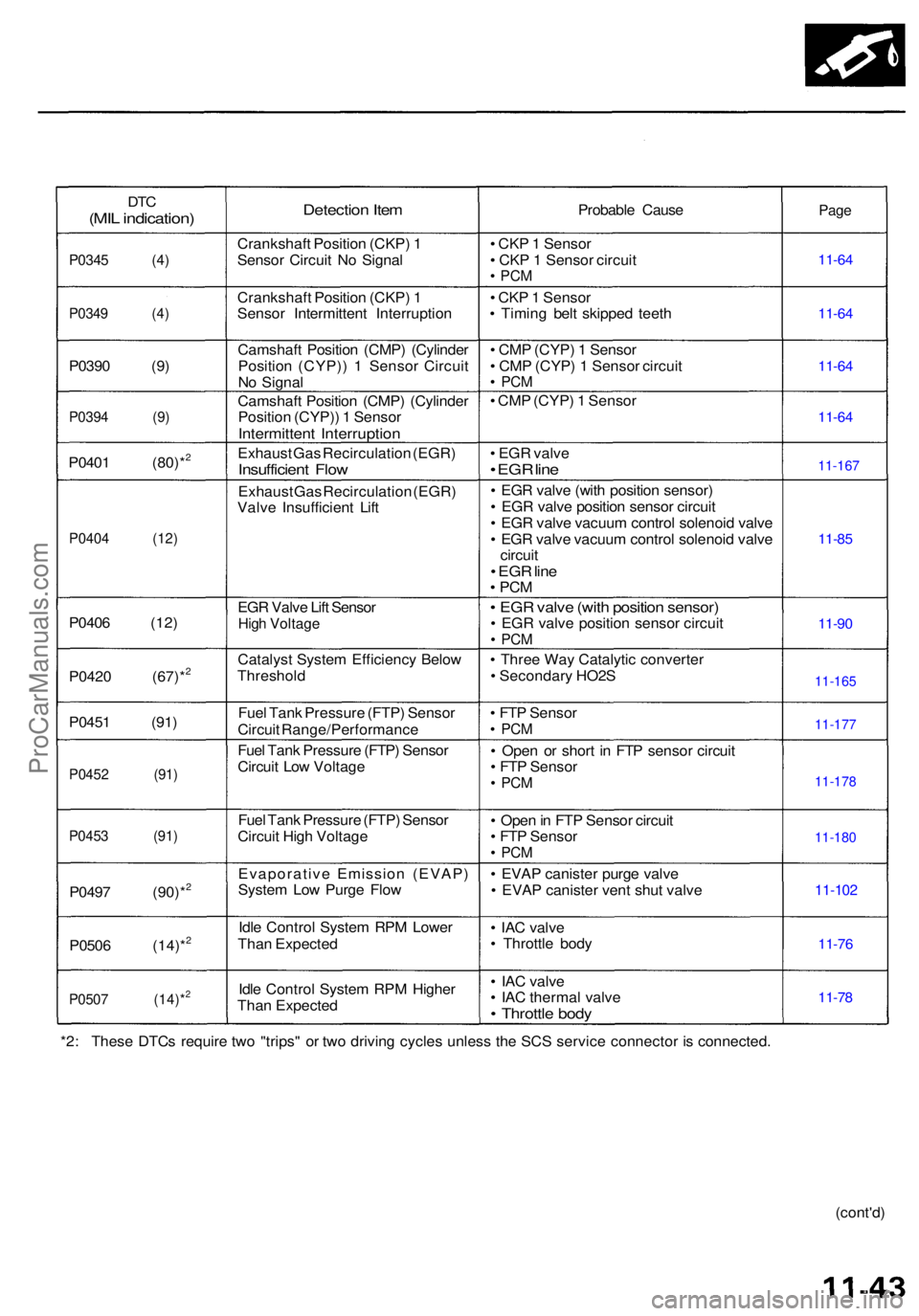
*2: Thes e DTC s requir e tw o "trips " o r tw o drivin g cycle s unles s th e SC S servic e connecto r i s connected .
(cont'd)
11-167
11-165
11-177
11-178
11-180
ProCarManuals.com
Page 136 of 1954
Troubleshooting
Diagnostic Troubl e Cod e (DTC ) Char t (cont'd )
DTC(MI L indication )
P0511 (14 )
P0560 (34 )
P060 7 (- )
P07x x (70)*
3
P0700** *
P1121 (7 )
P1122 (7 )
P1128 (5 )
P1129 (5 )
P1201P120 2P1203P120 4P120 5P1206
P1301P130 2P1303P1304P1305P1306
P131 6 (79 )
P1317 (79 )
P131 8 (79 )
P131 9 (79 )
P1336 (54 )
P133 7 (54 )
Detection Ite m
Idle Ai r Contro l (IAC ) Valv e
Circui t Failur e
PC M Back-u p Circui t Lo w Voltag e
Powertrai n Contro l Modul e (PCM )
Interna l Circui t Failur e
Automati c Transaxl e Syste m
Malfunctio n
Throttl e Positio n (TP ) Senso r signa l
Lowe r Tha n Expecte d
Throttl e Positio n (TP ) Senso r signa l
Highe r Tha n Expecte d
Manifol d Absolut e Pressur e (MAP )
Senso r signa l Lowe r Tha n Expecte d
Manifol d Absolut e Pressur e (MAP )
Senso r signa l Highe r Tha n Expecte d
No . 1 Cylinde r Misfir e
No . 2 Cylinde r Misfir e
No . 3 Cylinde r Misfir e
No . 4 Cylinde r Misfir e
No . 5 Cylinde r Misfir e
No . 6 Cylinde r Misfir e
No . 1 Cylinde r Misfir e
No . 2 Cylinde r Misfir e
No . 3 Cylinde r Misfir e
No . 4 Cylinde r Misfir e
No . 5 Cylinde r Misfir e
No . 6 Cylinde r Misfir e
Spar k Plu g Voltag e Detectio n
Circui t Malfunctio n
[Lef t Ban k (Ban k 2) ]
Spar k Plu g Voltag e Detectio n
Circui t Malfunctio n
[Righ t Ban k (Ban k 1) ]
Spar k Plu g Voltag e Detectio nModule Rese t Circui t Malfunctio n[Left Ban k (Ban k 2) ]
Spar k Plu g Voltag e Detectio n
Modul e Rese t Circui t Malfunctio n
[Righ t Ban k (Ban k 1) ]
Crankshaf t Positio n (CKP ) 2
Senso r Circui t Intermitten t
Interruption
Crankshaf t Positio n (CKP ) 2
Senso r Circui t N o Signa l
Probabl e Caus e
• IA C valv e
• IA C valv e circui t
• PC M
• PC M Back-u p Circui t• PC M
• PC M
• T P senso r
• T P senso r
• MA P senso r
• MA P senso r
• Injecto r
• Injecto r circui t
• Ignitio n syste m
• Lo w compressio n
• Ignitio n syste m
• Ope n o r shor t i n Spar k Plu g Voltag e
Detectio n Modul e circui t
• Spar k Plu g Voltag e Detectio n Modul e
• PC M
• Ope n o r shor t i n Spar k Plu g Voltag e
Detectio n Modul e circui t
• Spar k Plu g Voltag e Detectio n Modul e
• PC M
• Ope n o r shor t i n Spar k Plu g Voltag e
Detectio n Modul e Rese t circui t
• Spar k Plu g Voltag e Detectio n Modul e
• PC M
• Ope n o r shor t i n Spar k Plu g Voltag e
Detectio n Modul e Rese t circui t
• Spar k Plu g Voltag e Detectio n Modul e
• PC M
• CK P 2 Senso r• Timin g bel t skippe d teet h
• CK P 2 Senso r
• CK P 2 Senso r circui t
• PC M
Pag e
11-8 0
11-6 6
Sectio n 1 4
11-60
11-5 9
11-6 4
11-64
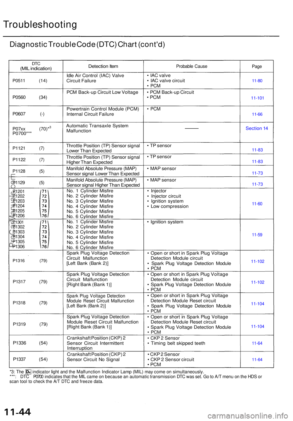
*3: Th e indicato r ligh t an d th e Malfunctio n Indicato r Lam p (MIL ) ma y com e o n simultaneously .***: DTC P0700 indicate s tha t th e MI L cam e o n becaus e a n automati c transmissio n DT C wa s set . G o to A/ T men u o n th e HD S o rsca n too l t o chec k th e A/ T DT C an d freez e data .
11-101
11-83
11-83
11-73
11-73
11-102 11-102
11-104
11-104
ProCarManuals.com
Page 137 of 1954
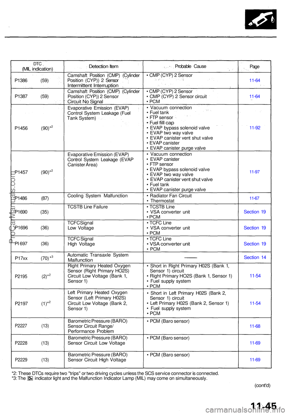
DTC(MIL indication )
P1386 (59 )
P138 7 (59 )
P145 6 (90)*
2
P145 7 (90)*2
P148 6 (87 )
P169 0 (35 )
P169 6 (36 )
PI 69 7 (36 )
P17xx (70 ) *3
P219 5 (2)*2
P219 7 (1)*2
P222 7 (13 )
P2228 (13 )
P2229 (13 )
Detection Ite m
Camshaf t Positio n (CMP ) (Cylinde r
Positio n (CYP) ) 2 Senso r
Intermitten t Interruptio n
Camshaft Positio n (CMP ) (Cylinde r
Positio n (CYP) ) 2 Senso r
Circuit N o Signa l
Evaporativ e Emissio n (EVAP )
Contro l Syste m Leakag e (Fue l
Tan k System )
Evaporativ e Emissio n (EVAP )
Contro l Syste m Leakag e (EVA P
Caniste r Area )
Coolin g Syste m Malfunctio n
TCST B Lin e Failur e
TCF C Signa l
Lo w Voltag e
TCF C Signa l
Hig h Voltag e
Automati c Transaxl e Syste m
Malfunctio n
Right Primar y Heate d Oxyge n
Senso r (Righ t Primar y HO2S )
Circui t Lo w Voltag e (Ban k 1 ,
Senso r 1 )
Lef t Primar y Heate d Oxyge n
Senso r (Lef t Primar y H02S )
Circui t Lo w Voltag e (Ban k 2 ,
Senso r 1 )
Barometri c Pressur e (BARO )
Senso r Circui t Range /
Performanc e Proble m
Barometri c Pressur e (BARO )
Senso r Circui t Lo w Voltag e
Barometri c Pressur e (BARO )
Senso r Circui t Hig h Voltag e Probabl
e Caus e
• CM P (CYP ) 2 Senso r
• CM P (CYP ) 2 Senso r
• CM P (CYP ) 2 Senso r circui t
• PC M
• Vacuu m connectio n
• Fue l tan k
• FT P senso r
• Fuel fill ca p• EVA P bypas s solenoi d valv e
• EVA P tw o wa y valv e
• EVA P caniste r ven t shu t valv e
• EVA P caniste r
• EVA P caniste r purg e valv e
• Vacuu m connectio n
• EVA P caniste r
• FT P senso r
• EVA P bypas s solenoi d valv e
• EVA P tw o wa y valv e
• EVA P caniste r ven t shu t valv e• Fue l tan k
• EVA P caniste r purg e valv e
• Radiato r Fa n Circui t
• Thermosta t
• TCST B Lin e
• VS A converte r uni t
• PC M
• TCF C Lin e
• VS A converte r uni t
• PC M
• TCF C Lin e• VS A converte r uni t• PC M
• Shor t i n Righ t Primar y H02 S (Ban k 1 ,
Senso r 1 ) circui t
• Righ t Primar y HO2 S (Ban k 1 , Senso r 1 )
• Fue l suppl y syste m
• PC M
• Shor t i n Lef t Primar y H02 S (Ban k 2 ,
Senso r 1 ) circui t
• Lef t Primar y H02 S (Ban k 2 , Senso r 1 )
• Fue l suppl y syste m
• PC M
• PC M (Bar o sensor )
• PC M (Bar o sensor )
• PC M (Bar o sensor ) Pag
e
11-6 4
11-6 4
11-9 2
11-97
11-6 7
Sectio n 1 9
Sectio n 1 9
Sectio n 1 9
Sectio n 1 4
11-5 4
11-5 4
11-6 8
11-6 9
11-6 9
*2: Thes e DTC s requir e tw o "trips " o r tw o drivin g cycle s unles s th e SC S servic e connecto r i s connected .*3: Th e indicato r ligh t an d th e Malfunctio n Indicato r Lam p (MIL ) ma y com e o n simultaneously .
(cont'd)
ProCarManuals.com
Page 138 of 1954
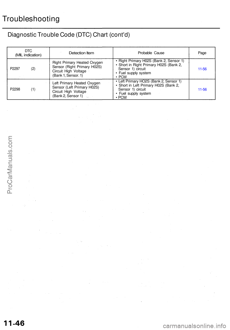
Troubleshooting
Diagnostic Troubl e Cod e (DTC ) Char t (cont'd )
DTC(MI L indication )
P2297 (2 )
P2298 (1 )
Detection Ite m
Righ t Primar y Heate d Oxyge n
Senso r (Righ t Primar y H02S )
Circui t Hig h Voltag e
(Ban k 1 , Sensor . 1 )
Lef t Primar y Heate d Oxyge n
Senso r (Lef t Primar y H02S )
Circui t Hig h Voltag e
(Ban k 2 , Senso r 1 ) Probabl
e Caus e
• Righ t Primar y H02 S (Ban k 2 , Senso r 1 )
• Shor t i n Righ t Primar y H02 S (Ban k 2 ,
Senso r 1 ) circui t
• Fue l suppl y syste m
• PC M
• Lef t Primar y HO2 S (Ban k 2 , Senso r 1 )
• Shor t i n Lef t Primar y H02 S (Ban k 2 ,
Senso r 1 ) circui t
• Fue l suppl y syste m
• PC M
Pag e
11-5 6
11-5 6
ProCarManuals.com
Page 139 of 1954
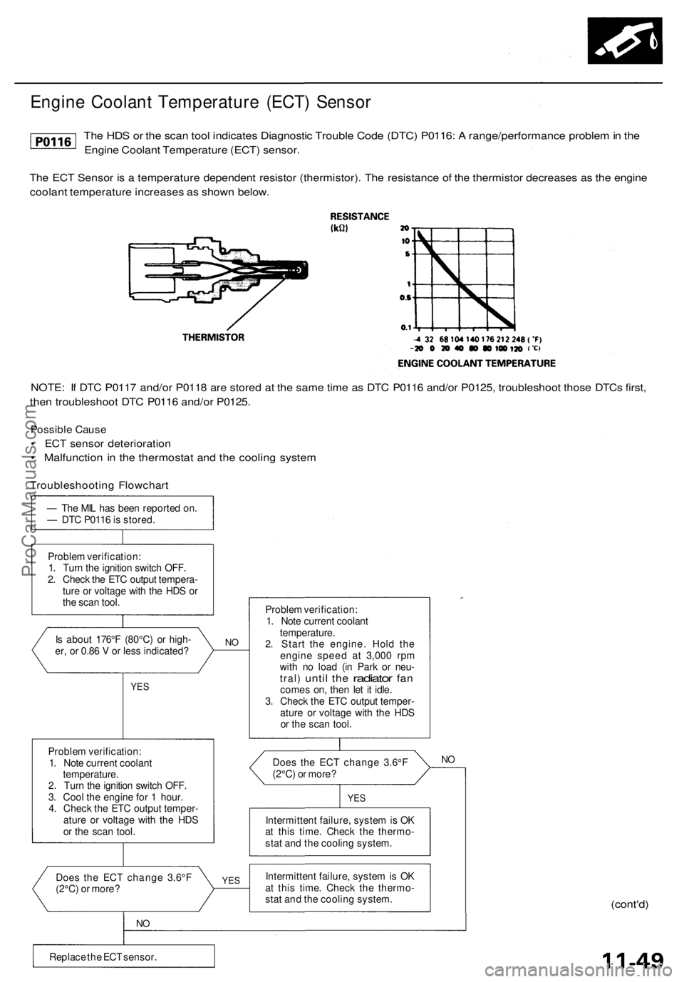
Engine Coolant Temperature (ECT) Sensor
The HDS or the scan tool indicates Diagnostic Trouble Code (DTC) P0116: A range/performance problem in the
Engine Coolant Temperature (ECT) sensor.
The ECT Sensor is a temperature dependent resistor (thermistor). The resistance of the thermistor decreases as the engine
coolant temperature increases as shown below.
NOTE: If DTC P0117 and/or P0118 are stored at the same time as DTC P0116 and/or P0125, troubleshoot those DTCs first,
then troubleshoot DTC P0116 and/or P0125.
Possible Cause
• ECT sensor deterioration
• Malfunction in the thermostat and the cooling system
Troubleshooting Flowchart
— The MIL has been reported on.
— DTC P0116 is stored.
Problem verification:
1. Turn the ignition switch OFF.
2. Check the ETC output tempera-
ture or voltage with the HDS or
the scan tool.
Is about 176°F (80°C) or high-
er, or 0.86 V or less indicated?
YES
Problem verification:
1. Note current coolant
temperature.
2. Turn the ignition switch OFF.
3. Cool the engine for 1 hour.
4. Check the ETC output temper-
ature or voltage with the HDS
or the scan tool.
Does the ECT change 3.6°F
(2°C) or more?
NO
Replace the ECT sensor.
NO
YES
Problem verification:
1. Note current coolant
temperature.
2. Start the engine. Hold the
engine speed at 3,000 rpm
with no load (in Park or neu-
tral)
until
the
radiator
fan
comes on, then let it idle.
3. Check the ETC output temper-
ature or voltage with the HDS
or the scan tool.
Does the ECT change 3.6°F
(2°C) or more?
NO
YES
Intermittent failure, system is OK
at this time. Check the thermo-
stat and the cooling system.
Intermittent failure, system is OK
at this time. Check the thermo-
stat and the cooling system.
(cont'd)ProCarManuals.com
Page 140 of 1954

PGM-FI System
Engine Coolant Temperature (ECT) Sensor (cont'd)
The HDS or the scan tool indicates Diagnostic Trouble Code (DTC) P0125: Engine Coolant Temperature
(ECT) sensor malfunction/slow response.
Is about 86°F (30°C) or less, or
2.61 V or higher indicated?
Intermittent failure, system is OK
at this time.
Check the thermostat and the
cooling system.
YES
Problem verification:
1. Let it idle for 6 minutes.
2. Check the ETC output temper-
ature or voltage with the HDS
or the scan tool.
Is about 86°F (30°C) or less, or
2.61 V or higher indicated?
Intermittent failure, system is OK
at this time.
Check the thermostat and the
cooling system.
YES
Replace the ECT sensor.
11-50
Problem verification:
1. Start the engine, and let it idle.
2. Check the ETC output temper-
ature or voltage with the HDS
or the scan tool.
— The MIL has been reported on
— DTC P0125 is stored.ProCarManuals.com