ACURA RL KA9 1996 Service Repair Manual
Manufacturer: ACURA, Model Year: 1996, Model line: RL KA9, Model: ACURA RL KA9 1996Pages: 1954, PDF Size: 61.44 MB
Page 141 of 1954
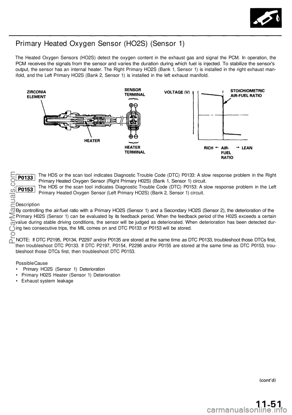
The HDS or the scan tool indicates Diagnostic Trouble Code (DTC) P0133: A slow response problem in the Right
Primary Heated Oxygen Sensor (Right Primary H02S) (Bank 1, Sensor 1) circuit.
The HDS or the scan tool indicates Diagnostic Trouble Code (DTC) P0153: A slow response problem in the Left
Primary Heated Oxygen Sensor (Left Primary HO2S) (Bank 2, Sensor 1) circuit.
Description
By controlling the air/fuel ratio with a Primary HO2S (Sensor 1) and a Secondary HO2S (Sensor 2), the deterioration of the
Primary H02S (Sensor 1) can be evaluated by its feedback period. When the feedback period of the H02S exceeds a certain
value during stable driving conditions, the sensor will be judged as deteriorated. When deterioration has been detected dur-
ing two consecutive trips, the MIL comes on and DTC P0133 or P0153 will be stored.
NOTE: If DTC P2195, P0134, P2297 and/or P0135 are stored at the same time as DTC P0133, troubleshoot those DTCs first,
then troubleshoot DTC P0133. If DTC P2197, P0154, P2298 and/or P0155 are stored at the same time as DTC P0153, trou-
bleshoot those DTCs first, then troubleshoot DTC P0153.
Possible Cause
• Primary HO2S (Sensor 1) Deterioration
• Primary H02S Heater (Sensor 1) Deterioration
• Exhaust system leakage
Primary Heated Oxygen Sensor (HO2S) (Sensor 1)
The Heated Oxygen Sensors (HO2S) detect the oxygen content in the exhaust gas and signal the PCM. In operation, the
PCM receives the signals from the sensor and varies the duration during which fuel is injected. To stabilize the sensor's
output, the sensor has an internal heater. The Right Primary HO2S (Bank 1, Sensor 1) is installed in the right exhaust man-
ifold, and the Left Primary HO2S (Bank 2, Sensor 1) is installed in the left exhaust manifold.ProCarManuals.com
Page 142 of 1954
PGM-FI System
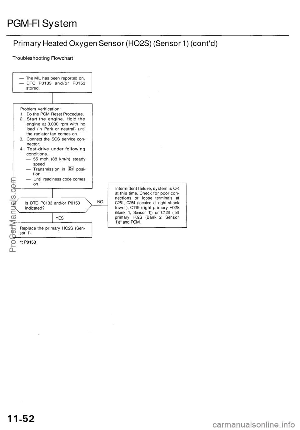
Primary Heated Oxygen Sensor (HO2S) (Sensor 1) (cont'd)
Troubleshooting Flowchart
Is DTC P0133 and/or P0153
indicated?
NO
YES
Intermittent failure, system is OK
at this time. Check for poor con-
nections or loose terminals at
C251, C254 (located at right shock
tower), C119 (right primary H02S
(Bank 1, Sensor 1)) or C126 (left
primary H02S (Bank 2, Sensor
1))*
and
PCM.
— The MIL has been reported on.
— DTC P0133 and/or P0153
stored.
Problem verification:
1. Do the PCM Reset Procedure.
2. Start the engine. Hold the
engine at 3,000 rpm with no
load (in Park or neutral) until
the radiator fan comes on.
3. Connect the SCS service con-
nector.
4. Test-drive under following
conditions.
— 55 mph (88 km/h) steady
speed
— Transmission in posi-
tion
— Until readiness code comes
on
Replace the primary HO2S (Sen-
sor 1).ProCarManuals.com
Page 143 of 1954
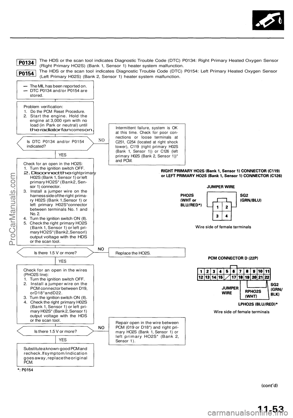
The HDS or the scan tool indicates Diagnostic Trouble Code (DTC) P0134: Right Primary Heated Oxygen Sensor
(Right Primary HO2S) (Bank 1, Sensor 1) heater system malfunction.
The HDS or the scan tool indicates Diagnostic Trouble Code (DTC) P0154: Left Primary Heated Oxygen Sensor
(Left Primary H02S) (Bank 2, Sensor 1) heater system malfunction.
The MIL has been reported on.
DTC P0134 and/or P0154 are
stored.
Problem verification:
1. Do the PCM Reset Procedure.
2. Start the engine. Hold the
engine at 3,000 rpm with no
load (in Park or neutral) until
the
radiator
fan
comes
on.
Is DTC P0134 and/or P0154
indicated?
YES
Check for an open in the HO2S:
1. Turn the ignition switch OFF.
2.
Disconnect
the
right primary
H02S (Bank 1, Sensor 1) or left
primary HO2S* (Bank2, Sen-
sor 1) connector.
3. Install a jumper wire on the
harness side of the right prima-
ry H02S (Bank 1,Sensor 1) or
left primary H02S*connector
between terminals No. 1 and
No. 2.
4. Turn the ignition switch ON (II).
5. Check the right primary HO2S
(Bank 1, Sensor 1) or left pri-
mary HO2S*(Bank2, Sensorl)
output voltage with the HDS
or the scan tool.
Is there 1.5 V or more?
YES
Check for an open in the wires
(PHO2S line):
1. Turn the ignition switch OFF.
2. Install a jumper wire on the
PCM connector between D19,
orD18*andD22.
3. Turn the ignition switch ON (II).
4. Check the right primary H02S
(Bank 1, Sensor 1) or left pri-
mary H02S* (Bank 2, Sensor 1)
output voltage with the HDS
or the scan tool.
Is there 1.5 V or more?
YES
NO
Intermittent failure, system is OK
at this time. Check for poor con-
nections or loose terminals at
C251, C254 (located at right shock
tower), C119 (right primary H02S
(Bank 1, Sensor 1)) or C126 (left
primary H02S (Bank 2, Sensor 1))*
and
PCM.
Replace the HO2S.
Repair open in the wire between
PCM (019 or D18*) and right pri-
mary HO2S (Bank 1, Sensor 1) or
left primary HO2S* (Bank 2,
Sensor 1).
Substitute a known-good PCM and
recheck. If symptom/indication
goes away, replace the original
PCM.ProCarManuals.com
Page 144 of 1954
PGM-FI Syste m
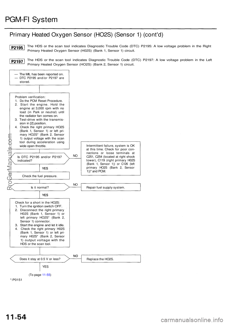
Primar y Heate d Oxyge n Senso r (HO2S ) (Senso r 1 ) (cont'd )
The HD S o r th e sca n too l indicate s Diagnosti c Troubl e Cod e (DTC ) P2195 : A lo w voltag e proble m in th e Righ t
Primar y Heate d Oxyge n Senso r (H02S ) (Ban k 1 , Senso r 1 ) circuit .
The HD S o r th e sca n too l indicate s Diagnosti c Troubl e Cod e (DTC ) P2197 : A lo w voltag e proble m in th e Lef t
Primar y Heate d Oxyge n Senso r (HO2S ) (Ban k 2 , Senso r 1 ) circuit .
— Th e MI L ha s bee n reporte d on .— DT C P219 5 and/o r P219 7 ar e
stored .
Proble m verification :
1 . D o th e PC M Rese t Procedure .
2 . Star t th e engine . Hol d th e
engin e a t 3,00 0 rp m wit h n oloa d (i n Par k o r neutral ) unti lthe radiato r fa n come s on .3. Test-driv e wit h th e transmis -sion in [2 ] position .4. Chec k th e righ t primar y HO2 S
(Ban k 1 , Senso r 1 ) o r lef t pri -
mar y HO2S * (Ban k 2 , Senso r
1 ) outpu t voltag e wit h th e sca n
too l durin g acceleratio n usin g
wide ope n throttle .
Is DT C P219 5 and/o r P219 7indicated ?
Does i t sta y a t 0. 5 V or less ?
YES
(To pag e 11-55 )
NO
Intermitten t failure , syste m is O K
a t thi s time . Chec k fo r poo r con -
nection s o r loos e terminal s a tC251 , C25 4 (locate d a t righ t shoc k
tower) , C11 9 (righ t primar y H02 S
(Ban k 1 , Senso r 1) ) o r C12 6 (lef tprimar y HO2 S (Ban k 2 , Senso r1))* an d PCM .
NORepai r fue l suppl y system .
Replac e th e HO2S .
*:P015 1
Check fo r a shor t i n th e HO2S :1. Tur n th e ignitio n switc h OFF .2. Disconnec t th e righ t primar yH02S (Ban k 1 , Senso r 1 ) o r
lef t primar y HO2S * (Ban k 2 ,
Senso r 1 ) connector .
3. Star t th e engin e an d le t i t idle .4. Chec k th e righ t primar y H02 S
(Ban k 1 , Senso r 1 ) o r lef t pri -
mar y H02S * (Ban k 2 , Senso r
1) outpu t voltag e wit h th eHD S o r th e sca n tool .
I
s i t normal ?
Chec
k th e fue l pressure .
ProCarManuals.com
Page 145 of 1954
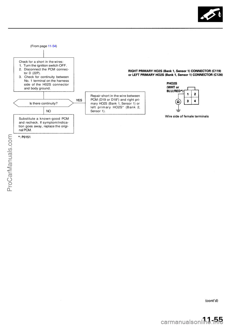
(From pag e 11-54 )
Check fo r a shor t i n th e wires :1. Tur n th e ignitio n switc h OFF .2. Disconnec t th e PC M connec -tor D (22P) .3. Chec k fo r continuit y betwee n
No . 1 termina l o n th e harnes s
sid e o f th e H02 S connecto r
an d bod y ground .
I s ther e continuity ?
NO
Substitut e a known-goo d PC M
an d recheck . I f symptom/indica -
tio n goe s away , replac e th e origi -
nal PCM .
Repai r shor t i n th e wir e betwee n
PC M (D1 9 o r D18* ) an d righ t pri -
mar y HO2 S (Ban k 1 , Senso r 1 ) o rlef t primar y HO2S * (Ban k 2 ,Senso r 1) .
ProCarManuals.com
Page 146 of 1954
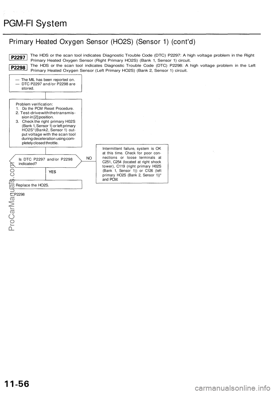
PGM-FI System
Primary Heated Oxygen Sensor (HO2S) (Sensor 1) (cont'd)
The HDS or the scan tool indicates Diagnostic Trouble Code (DTC) P2297: A high voltage problem in the Right
Primary Heated Oxygen Sensor (Right Primary HO2S) (Bank 1, Sensor 1) circuit.
The HDS or the scan tool indicates Diagnostic Trouble Code (DTC) P2298: A high voltage problem in the Left
Primary Heated Oxygen Sensor (Left Primary HO2S) (Bank 2, Sensor 1) circuit.
— The MIL has been reported on.
— DTC P2297 and/or P2298 are
stored.
Problem verification:
1. Do the PCM Reset Procedure.
2. Test-drive with the transmis-
sion in [2] position.
3. Check the right primary H02S
(Bank 1, Sensor 1) or left primary
HO2S*(Bank2, Sensor 1) out-
put voltage with the scan tool
during deceleration using com-
pletely closed throttle.
Is DTC P2297 and/or P2298
indicated?
NO
Intermittent failure, system is OK
at this time. Check for poor con-
nections or loose terminals at
C251, C254 (located at right shock
tower), C119 (right primary H02S
(Bank 1, Sensor 1)) or C126 (left
primary HO2S (Bank 2, Sensor 1))*
and
PCM.
*: P2298
Replace the HO2S.ProCarManuals.com
Page 147 of 1954
![ACURA RL KA9 1996 Service Repair Manual
Fuel Supply System
The HDS or the scan tool indicates Diagnostic Trouble Code (DTC) P0171: The fuel system is too lean [Right
Bank (Bank 1)].
The HDS or the scan tool indicates Diagnostic Trouble ACURA RL KA9 1996 Service Repair Manual
Fuel Supply System
The HDS or the scan tool indicates Diagnostic Trouble Code (DTC) P0171: The fuel system is too lean [Right
Bank (Bank 1)].
The HDS or the scan tool indicates Diagnostic Trouble](/img/32/56992/w960_56992-146.png)
Fuel Supply System
The HDS or the scan tool indicates Diagnostic Trouble Code (DTC) P0171: The fuel system is too lean [Right
Bank (Bank 1)].
The HDS or the scan tool indicates Diagnostic Trouble Code (DTC) P0172: The fuel system is too rich [Right
Bank (Bank 1)].
The HDS or the scan tool indicates Diagnostic Trouble Code (DTC) P0174: The fuel system is too lean [Left Bank
(Bank 2)].
The HDS or the scan tool indicates Diagnostic Trouble Code (DTC) P0175: The fuel system is too rich [Left Bank
(Bank 2)].
Description
By monitoring the Long Term Fuel Trim, long term malfunctions in the fuel system will be detected.
If a
malfunction
has
been detected
during
two
consecutive
trips,
the MIL
will
come
on and DTC
P0171,
P0172, P0174
and/or P0175 will be stored.
NOTE: If some of the DTCs listed below are stored at the same time as DTC P0171, P0172, P0174 and/or P0175, trou-
bleshoot those DTCs first, then troubleshoot DTC P0171, P0172, P0174 and/or P0175.
P0107, P0108, P1128, P1129: MAP Sensor
P0135: Right Primary HO2S Heater (Bank 1, Sensor 1)
P0137, P0138: Secondary HO2S (Sensor 2)
P0141: Secondary HO2S Heater (Sensor 2)
P0155: Left Primary H02S Heater (Bank 2, Sensor 1)
P0401: EGR Flow Insufficient
P0404: EGR Valve Lift Insufficient
P0406: EGR Valve Position Sensor High Voltage
Possible Cause
Fuel Pump insufficient flow/pressure
Fuel Feed Line clogged, leaking
Fuel Pressure Regulator stuck open
Fuel Filter clogged
Injector clogged, air inclusion
Gasoline doesn't meet Owner's Manual spec.
Primary H02S (Sensor 1) deteriorated
EGR System insufficient flow
Exhaust leak
Fuel Pressure Regulator clogged, stuck closed
Fuel Return Pipe clogged
Injector leaking
Gasoline doesn't meet Owner's Manual spec.
Primary HO2S (Sensor 1) deteriorated
EGR System malfunction (too much flow)
EVAP Canister Purge Valve leaking, stuck opened
(cont'd)ProCarManuals.com
Page 148 of 1954
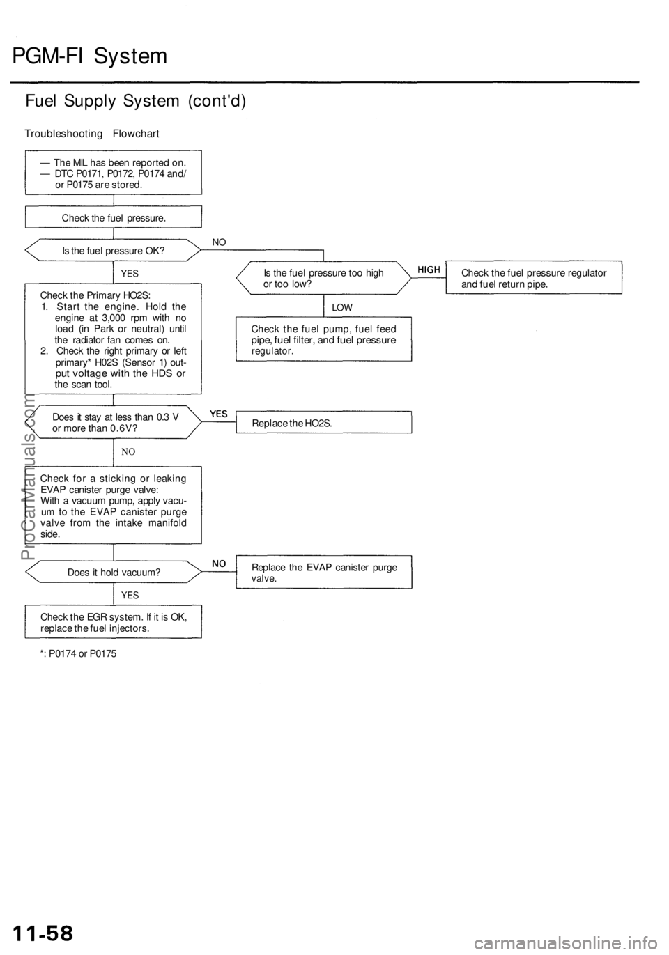
PGM-FI System
Fuel Supply System (cont'd)
Troubleshooting Flowchart
— The MIL has been reported on.
— DTC P0171, P0172, P0174 and/
or P0175 are stored.
Check the fuel pressure.
Is the fuel pressure OK?
NO
YES
Check the Primary HO2S:
1. Start the engine. Hold the
engine at 3,000 rpm with no
load (in Park or neutral) until
the radiator fan comes on.
2. Check the right primary or left
primary* H02S (Sensor 1) out-
put voltage with the HDS or
the scan tool.
Is the fuel pressure too high
or too low?
Check the fuel pressure regulator
and fuel return pipe.
LOW
Check the fuel pump, fuel feed
pipe, fuel filter, and fuel pressure
regulator.
Does it stay at less than 0.3 V
or more than 0.6V?
Replace the HO2S.
NO
Check for a sticking or leaking
EVAP canister purge valve:
With a vacuum pump, apply vacu-
um to the EVAP canister purge
valve from the intake manifold
side.
Does it hold vacuum?
Replace the EVAP canister purge
valve.
YES
Check the EGR system. If it is OK,
replace the fuel injectors.
*: P0174 or P0175ProCarManuals.com
Page 149 of 1954
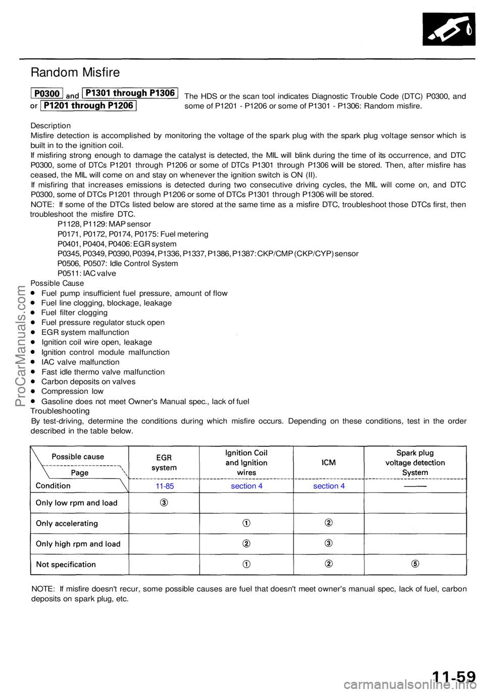
Random Misfir e
The HD S o r th e sca n too l indicate s Diagnosti c Troubl e Cod e (DTC ) P0300 , an d
som e o f P120 1 - P120 6 o r som e o f P130 1 - P1306 : Rando m misfire .
Descriptio n
Misfire detectio n i s accomplishe d b y monitorin g th e voltag e o f th e spar k plu g wit h th e spar k plu g voltag e senso r whic h i s
buil t i n to th e ignitio n coil .
If misfirin g stron g enoug h t o damag e th e catalys t i s detected , th e MI L wil l blin k durin g th e tim e o f it s occurrence , an d DT C
P0300 , som e
of DTC s P120 1 throug h P1206 or som e of DTC s P130 1 throug h P1306 will be stored . Then , after misfir e has
ceased , th e MI L wil l com e o n an d sta y o n wheneve r th e ignitio n switc h is O N (II) .
I f misfirin g tha t increase s emission s i s detecte d during two consecutiv e drivin g cycles , th e MI L wil l com e on , an d DT C
P0300 , som e o f DTC s P120 1 throug h P120 6 o r som e o f DTC s P130 1 throug h P130 6 wil l b e stored .
NOTE : I f som e o f th e DTC s liste d belo w ar e store d a t th e sam e tim e a s a misfir e DTC , troubleshoo t thos e DTC s first , the n
troubleshoo t th e misfir e DTC .
P1128 , P1129 : MA P senso r
P0171 , P0172 , P0174 , P0175 : Fue l meterin g
P0401 , P0404 , P0406 : EG R syste m
P0345 , P0349 , P0390 , P0394 , P1336 , P1337 , P1386 , P1387 : CKP/CM P (CKP/CYP ) senso r
P0506 , P0507 : Idl e Contro l Syste m
P0511 : IA C valv e
Possibl e Caus e
Fuel pum p insufficien t fue l pressure , amoun t o f flo w
Fue l lin e clogging , blockage , leakag e
Fue l filte r cloggin g
Fue l pressur e regulato r stuc k ope n
EG R syste m malfunctio n
Ignitio n coi l wir e open , leakag e
Ignitio n contro l modul e malfunctio n
IA C valv e malfunctio n
Fas t idl e therm o valv e malfunctio n
Carbo n deposit s o n valve s
Compressio n lo w
Gasolin e doe s no t mee t Owner' s Manua l spec. , lac k o f fue l
Troubleshootin g
By test-driving , determin e th e condition s during which misfir e occurs . Dependin g o n thes e conditions , tes t i n th e orde r
describe d i n th e tabl e below .
NOTE : I f misfir e doesn' t recur , som e possibl e cause s ar e fue l tha t doesn' t mee t owner' s manua l spec , lac k o f fuel , carbo n
deposit s o n spar k plug , etc .
11-8 5 sectio n 4 section 4
ProCarManuals.com
Page 150 of 1954
PGM-FI System
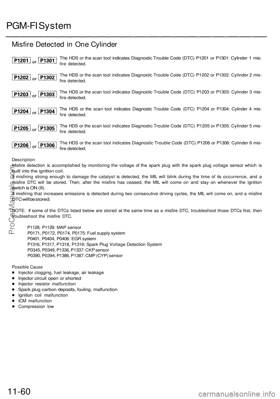
Description
Misfire detection is accomplished by monitoring the voltage of the spark plug with the spark plug voltage sensor which is
built into the ignition coil.
If misfiring strong enough to damage the catalyst is detected, the MIL will blink during the time of its occurrence, and a
misfire DTC will be stored. Then, after the misfire has ceased, the MIL will come on and stay on whenever the ignition
switch is ON (II).
If misfiring that increases emissions is detected during two consecutive driving cycles, the MIL will come on, and a misfire
DTC will be stored.
NOTE: If some of the DTCs listed below are stored at the same time as a misfire DTC, troubleshoot those DTCs first, then
troubleshoot the misfire DTC.
P1128, P1129: MAP sensor
P0171, P0172, P0174, P0175: Fuel supply system
P0401, P0404, P0406: EGR system
P1316, P1317, P1318, P1319: Spark Plug Voltage Detection System
P0345, P0349, P1336, P1337: CKP sensor
P0390, P0394, P1386, P1387: CMP (CYP) sensor
Possible Cause
Injector clogging, fuel leakage, air leakage
Injector circuit open or shorted
Injector resistor malfunction
Spark plug carbon deposits, fouling, malfunction
Ignition coil malfunction
ICM malfunction
Compression low
11-60
The HDS or the scan tool indicates Diagnostic Trouble Code (DTC) P1201 or P1301: Cylinder 1 mis-
fire detected.
The HDS or the scan tool indicates Diagnostic Trouble Code (DTC) P1202 or P1302: Cylinder 2 mis-
fire detected.
The HDS or the scan tool indicates Diagnostic Trouble Code (DTC) P1203 or P1303: Cylinder 3 mis-
fire detected.
The HDS or the scan tool indicates Diagnostic Trouble Code (DTC) P1204 or P1304: Cylinder 4 mis-
fire detected.
The HDS or the scan tool indicates Diagnostic Trouble Code (DTC) P1205 or P1305: Cylinder 5 mis-
fire detected.
The HDS or the scan tool indicates Diagnostic Trouble Code (DTC) P1206 or P1306: Cylinder 6 mis-
fire detected.
Misfire Detected in One CylinderProCarManuals.com