ACURA RL KA9 1996 Service Repair Manual
Manufacturer: ACURA, Model Year: 1996, Model line: RL KA9, Model: ACURA RL KA9 1996Pages: 1954, PDF Size: 61.44 MB
Page 1541 of 1954
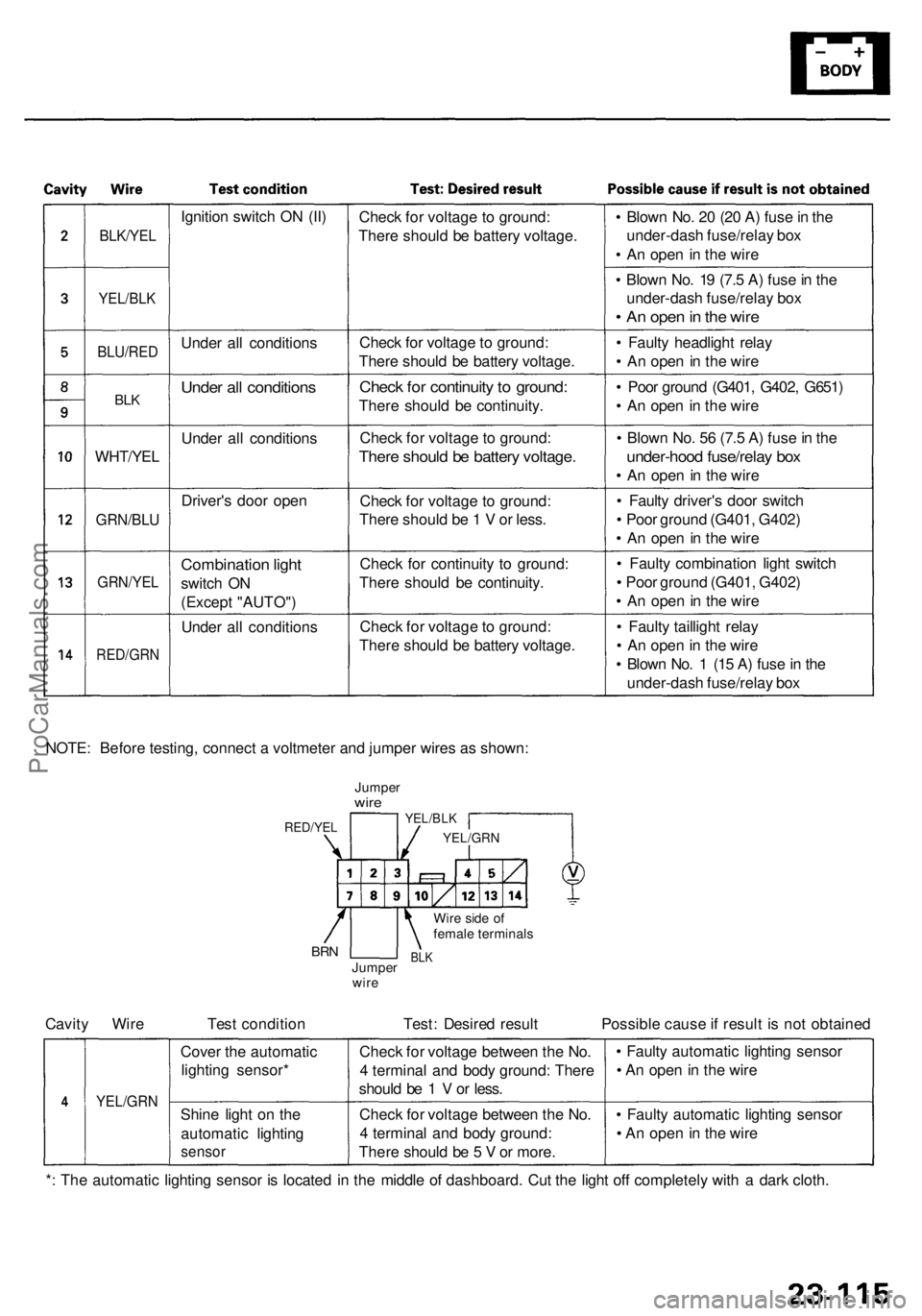
BLK/YEL
YEL/BLK
BLU/RE D
BLK
WHT/YE L
GRN/BLU
GRN/YE L
RED/GR N
Ignition switc h O N (II )
Unde r al l condition s
Under al l condition s
Under al l condition s
Driver' s doo r ope n
Combinatio n ligh t
switc h O N
(Excep t "AUTO" )
Unde r al l condition sChec
k fo r voltag e to ground :
Ther e shoul d b e batter y voltage .
Chec k fo r voltag e to ground:
Ther e shoul d b e batter y voltage .
Check fo r continuit y to ground :
There shoul d b e continuity .
Chec k fo r voltag e to ground :
There shoul d b e batter y voltage .
Check fo r voltag e t o ground :
Ther e shoul d b e 1 V or less .
Chec k fo r continuit y t o ground :
Ther e shoul d b e continuity .
Chec k fo r voltag e to ground :
Ther e shoul d b e batter y voltage .•
Blow n No . 2 0 (2 0 A ) fus e in th e
under-das h fuse/rela y bo x
• A n ope n in th e wir e
• Blow n No . 1 9 (7. 5 A ) fus e in th e
under-das h fuse/rela y bo x
• A n ope n in th e wir e
• Fault y headligh t rela y
• A n ope n in th e wir e
• Poo r groun d (G401 , G402 , G651 )
• A n ope n in th e wir e
• Blow n No . 5 6 (7. 5 A ) fus e in th e
under-hoo d fuse/rela y bo x
• A n ope n in th e wir e
• Fault y driver' s doo r switc h
• Poo r groun d (G401 , G402 )
• A n ope n in th e wir e
• Fault y combinatio n ligh t switc h
• Poo r ground (G401, G402 )
• A n ope n in th e wir e
• Fault y tailligh t rela y
• A n ope n in th e wir e
• Blow n No . 1 (1 5 A ) fus e in th e
under-das h fuse/rela y bo x
NOTE : Befor e testing , connec t a voltmete r an d jumpe r wire s a s shown :
JumperwireYEL/BL K
YEL/GR N
Wire sid e o f
femal e terminal s
BLKJumpe r
wir eBRN
RED/YE L
Cavity Wir e Tes t conditio n Test : Desire d resul t Possibl e caus e if resul t i s no t obtaine d
YEL/GR N
Cover th e automati c
lightin g sensor *
Shin e ligh t o n th e
automati c lightin g
sensor
Check fo r voltag e betwee n th e No .
4 termina l an d bod y ground : Ther e
shoul d b e 1 V or less .
Chec k fo r voltag e betwee n th e No .
4 termina l an d bod y ground :
Ther e shoul d b e 5 V or more . •
Fault y automati c lightin g senso r
• A n ope n in th e wir e
• Fault y automati c lightin g senso r
• A n ope n in th e wir e
* : Th e automati c lightin g senso r i s locate d i n th e middl e o f dashboard . Cu t th e ligh t of f completel y wit h a dar k cloth .
ProCarManuals.com
Page 1542 of 1954
Lighting Syste m
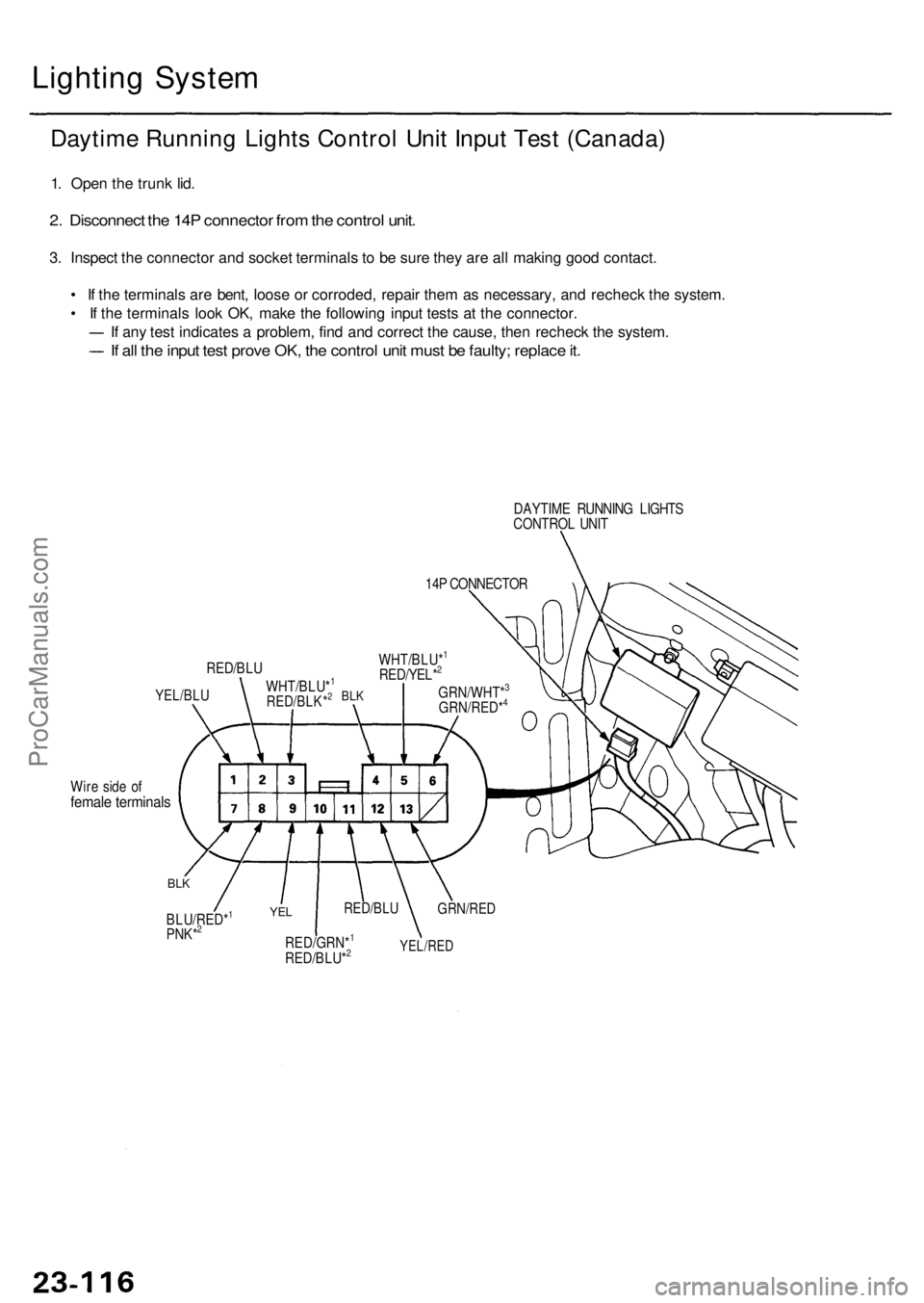
Daytim e Runnin g Light s Contro l Uni t Inpu t Tes t (Canada )
1. Ope n th e trun k lid .
2. Disconnec t th e 14 P connecto r fro m th e contro l unit .
3. Inspec t th e connecto r an d socke t terminal s t o b e sur e the y ar e al l makin g goo d contact .
• I f th e terminal s ar e bent , loos e o r corroded , repai r the m a s necessary , an d rechec k th e system .
• I f th e terminal s loo k OK , mak e th e followin g inpu t test s a t th e connector .
I f an y tes t indicate s a problem , fin d an d correc t th e cause , the n rechec k th e system .
If al l th e inpu t tes t prov e OK , th e contro l uni t mus t b e faulty ; replac e it .
DAYTIM E RUNNIN G LIGHT S
CONTRO L UNI T
14 P CONNECTO R
YEL/BLU
RED/BL U
WHT/BLU*1
RED/BLK*2
WHT/BLU*1
RED/YEL*2
GRN/WHT*3
GRN/RED*4BL K
Wir e sid e o ffemal e terminal s
BLK
BLU/RED*1
PNK*2YE L
RED/GRN*1
RED/BLU*2
RED/BL U
YEL/RE D
GRN/RE D
ProCarManuals.com
Page 1543 of 1954
ProCarManuals.com
Page 1544 of 1954
Lighting Syste m
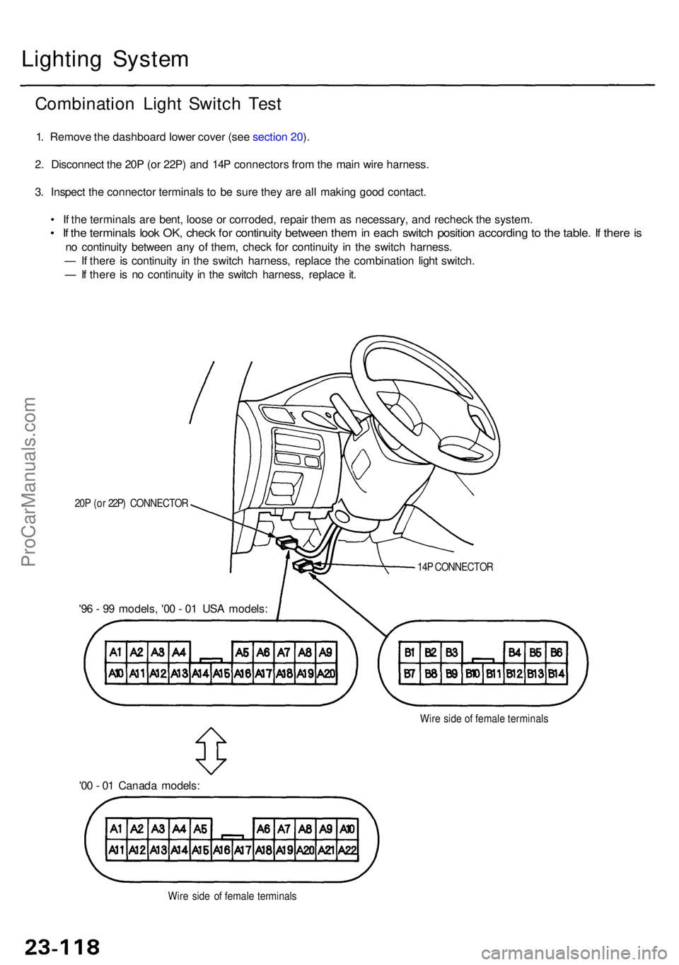
Combinatio n Ligh t Switc h Tes t
1. Remov e th e dashboar d lowe r cove r (se e sectio n 20 ).
2 . Disconnec t th e 20 P (o r 22P ) an d 14 P connector s fro m th e mai n wir e harness .
3 . Inspec t th e connecto r terminal s t o b e sur e the y ar e al l makin g goo d contact .
• I f th e terminal s ar e bent , loos e o r corroded , repai r the m a s necessary , an d rechec k th e system .
• I f th e terminal s loo k OK , chec k fo r continuit y betwee n the m in eac h switc h positio n accordin g to th e table . I f ther e is
n o continuit y betwee n an y o f them , chec k fo r continuit y i n th e switc h harness .
— If ther e i s continuit y i n th e switc h harness , replac e th e combinatio n ligh t switch .
— If ther e is n o continuit y i n th e switc h harness , replac e it .
14 P CONNECTO R
Wir e sid e o f femal e terminal s
20
P (o r 22P ) CONNECTO R
'96 - 9 9 models , '0 0 - 0 1 US A models :
'0 0 - 0 1 Canad a models :
Wire sid e o f femal e terminal s
ProCarManuals.com
Page 1545 of 1954
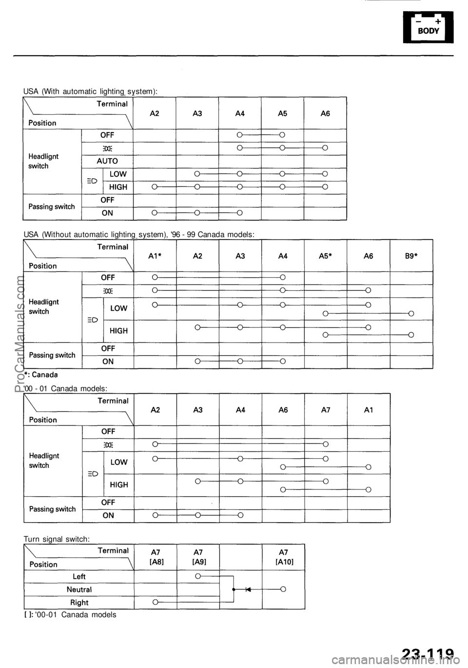
USA (Wit h automati c lightin g system) :
US A (Withou t automati c lightin g system) , '9 6 - 9 9 Canad a models :
'0 0 - 0 1 Canad a models :
Tur n signa l switch :
'00-0 1 Canad a model s
ProCarManuals.com
Page 1546 of 1954
Lighting Syste m
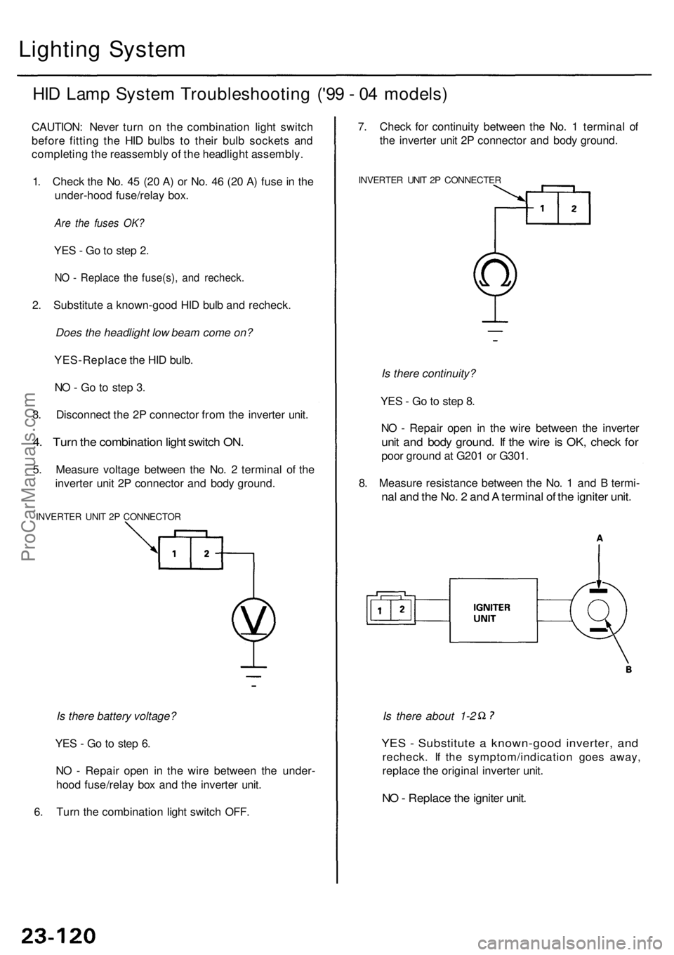
HID Lam p Syste m Troubleshootin g ('9 9 - 0 4 models )
CAUTION : Neve r tur n o n th e combinatio n ligh t switc h
befor e fittin g th e HI D bulb s t o thei r bul b socket s an d
completin g th e reassembl y o f th e headligh t assembly .
1 . Chec k th e No . 4 5 (2 0 A ) o r No . 4 6 (2 0 A ) fus e in th e
under-hoo d fuse/rela y box .
Are the fuses OK?
YES - G o to ste p 2 .
NO - Replac e th e fuse(s) , an d recheck .
2. Substitut e a known-goo d HI D bul b an d recheck .
Does the headlight low beam come on?
YES-Replac e th e HI D bulb .
N O - G o t o ste p 3 .
3 . Disconnec t th e 2 P connecto r fro m th e inverte r unit .
4. Tur n th e combinatio n ligh t switc h ON .
5. Measur e voltag e betwee n th e No . 2 termina l o f th e
inverte r uni t 2 P connecto r an d bod y ground .
INVERTE R UNI T 2 P CONNECTO R
Is there battery voltage?
YE S - G o to ste p 6 .
N O - Repai r ope n i n th e wir e betwee n th e under -
hoo d fuse/rela y bo x an d th e inverte r unit .
6 . Tur n th e combinatio n ligh t switc h OFF .
YES - Substitut e a known-goo d inverter , an d
recheck . I f th e symptom/indicatio n goe s away ,
replac e th e origina l inverte r unit .
NO - Replac e th e ignite r unit .
Is there about 1-2
7
. Chec k fo r continuit y betwee n th e No . 1 termina l o f
th e inverte r uni t 2 P connecto r an d bod y ground .
INVERTE R UNI T 2 P CONNECTE R
Is there continuity?
YE S - G o to ste p 8 .
N O - Repai r ope n i n th e wir e betwee n th e inverte r
unit an d bod y ground . I f th e wir e is OK , chec k fo r
poo r groun d a t G20 1 o r G301 .
8 . Measur e resistanc e betwee n th e No . 1 an d B termi -
nal an d th e No . 2 an d A termina l o f th e ignite r unit .
ProCarManuals.com
Page 1547 of 1954
Headlights
Combinatio n Ligh t Switc h
Replacemen t
1. Remov e th e dashboar d lowe r cove r (se e sectio n 20 ).
2 . Remove the steering column covers (see
section 17 ).
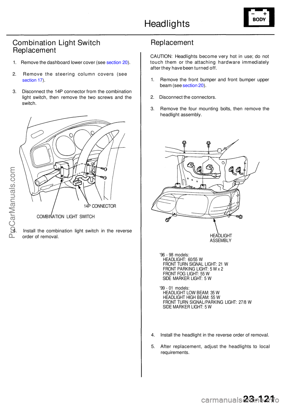
3 . Disconnec t th e 14 P connecto r fro m th e combinatio n
ligh t switch , the n remov e th e tw o screw s an d th e
switch .
4 . Instal l th e combinatio n ligh t switc h i n th e revers e
orde r o f removal .
COMBINATIO N LIGH T SWITC H
14
P CONNECTO R
Replacemen t
CAUTION: Headlight s becom e ver y ho t i n use ; d o no t
touc h the m o r th e attachin g hardwar e immediatel y
afte r the y hav e bee n turne d off .
1 . Remov e th e fron t bumpe r an d fron t bumpe r uppe r
bea m (se e sectio n 20 ).
2 . Disconnec t th e connectors .
3 . Remov e th e fou r mountin g bolts , the n remov e th e
headligh t assembly .
HEADLIGH T
ASSEMBL Y
'9 6 - 9 8 models :
HEADLIGHT : 60/5 5 W
FRON T TUR N SIGNA L LIGHT : 2 1 W
FRON T PARKIN G LIGHT : 5 W x 2
FRON T FO G LIGHT : 5 5 W
SID E MARKE R LIGHT : 5 W
'9 9 - 0 1 models :
HEADLIGH T LO W BEAM : 3 5 W
HEADLIGH T HIG H BEAM : 5 5 W
FRON T TUR N SIGNAL/PARKIN G LIGHT : 27/ 8 W
SID E MARKE R LIGHT : 5 W
4. Instal l th e headligh t i n th e revers e orde r o f removal .
5 . Afte r replacement , adjus t th e headlight s t o loca l
requirements .
ProCarManuals.com
Page 1548 of 1954
Headlights
HID Bul b Remova l ('9 9 - 0 4 models )
A transien t hig h tensio n (25,00 0 V ) occur s
a t th e bul b socket s o f th e hig h intensit y discharg e (HID )
lamp s whe n th e combinatio n ligh t switc h is turne d ON .
I t ma y caus e seriou s electrica l shoc k o r electrocutio n if
yo u d o no t observ e th e caution s below .
CAUTION :
• Neve r tur n o n th e combinatio n ligh t switc h befor e
fittin g th e HI D bulb s t o thei r bul b socket s an d com -
pletin g th e reassembl y o f th e headligh t assembly .
• T o preven t electrocution , d o no t servic e th e head -
light s assembl y i n we t conditions , suc h a s rai n o r
snow , nea r a sprinkle r system , o r whe n you r hand s
are wet .
• D o no t touc h th e surfac e o f th e HI D bulb s wit h you r
bar e hand s an d d o no t stai n i t wit h an y oil s an d
fats .
• D o no t disassembl e th e inverte r uni t an d th e ignite r
unit .
• D o no t tur n o n th e HI D bul b b y usin g a powe r
sourc e othe r tha n th e batter y mounte d o n you r
vehicle .
1. Mak e sur e yo u hav e th e anti-thef t cod e fo r th e radi o
an d th e navigatio n system , the n writ e dow n th e fre -
quencie s fo r th e radio' s prese t buttons .
2. Tur n th e combinatio n ligh t switc h OFF .
3. Disconnec t th e batter y negativ e cable , the n discon -
nec t th e positiv e cable .
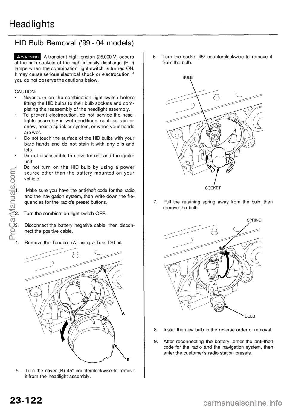
4 . Remov e th e Tor x bol t (A ) usin g a Tor x T2 0 bit .
5 . Tur n th e cove r (B ) 45 ° counterclockwis e t o remov e
i t fro m th e headligh t assembly . 8
. Instal l th e ne w bul b in th e revers e orde r o f removal .
9. Afte r reconnectin g th e battery , ente r th e anti-thef t
code fo r th e radi o an d th e navigatio n system , the n
ente r th e customer' s radi o statio n presets .
BULB
SPRIN G
6. Tur n th e socke t 45 ° counterclockwis e t o remov e i t
fro m th e bulb .
BULB
7. Pul l th e retainin g sprin g awa y fro m th e bulb , the n
remov e th e bulb .
SOCKE T
ProCarManuals.com
Page 1549 of 1954
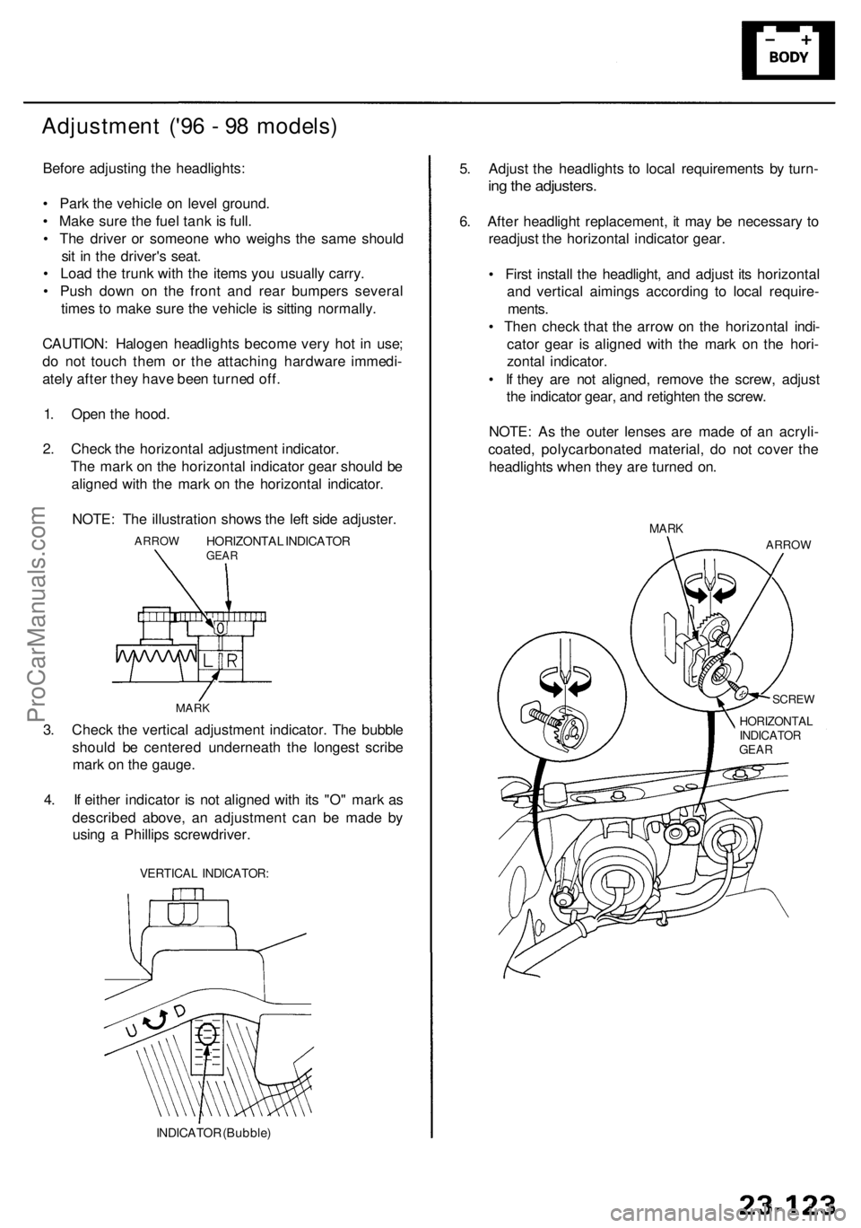
Adjustment ('9 6 - 9 8 models )
Before adjustin g th e headlights :
• Par k th e vehicl e o n leve l ground .
• Mak e sur e th e fue l tan k i s full .
• Th e drive r o r someon e who weigh s th e sam e shoul d
si t i n th e driver' s seat .
• Loa d th e trun k wit h th e item s yo u usuall y carry .
• Pus h dow n o n th e fron t an d rea r bumper s severa l
time s t o mak e sur e th e vehicl e i s sittin g normally .
CAUTION : Haloge n headlight s becom e ver y ho t i n use ;
d o no t touc h the m o r th e attachin g hardwar e immedi -
atel y afte r the y hav e bee n turne d off .
1 . Ope n th e hood .
2 . Chec k th e horizonta l adjustmen t indicator .
Th e mar k o n th e horizonta l indicato r gea r shoul d b e
aligne d wit h th e mar k o n th e horizonta l indicator .
NOTE : Th e illustratio n show s th e lef t sid e adjuster .
HORIZONTA L INDICATO RGEARARRO W
MARK
3. Chec k th e vertica l adjustmen t indicator . Th e bubbl e
shoul d b e centere d underneat h th e longes t scrib e
mar k o n th e gauge .
4 . I f eithe r indicato r i s no t aligne d wit h it s "O " mar k a s
describe d above , a n adjustmen t ca n b e mad e b y
usin g a Phillip s screwdriver .
VERTICAL INDICATOR :
INDICATOR (Bubble )
5. Adjus t th e headlight s t o loca l requirement s b y turn -
ing th e adjusters .
6. Afte r headligh t replacement , i t ma y b e necessar y t o
readjus t th e horizonta l indicator gear.
• Firs t instal l th e headlight , an d adjus t it s horizonta l
an d vertica l aiming s accordin g t o loca l require -
ments .
• The n chec k tha t th e arro w o n th e horizonta l indi -
cato r gea r i s aligne d wit h th e mar k o n th e hori -
zonta l indicator .
• I f the y ar e no t aligned , remov e th e screw , adjus t
th e indicato r gear , an d retighte n th e screw .
NOTE : A s th e oute r lense s ar e mad e o f a n acryli -
coated , polycarbonate d material , d o no t cove r th e
headlight s whe n the y ar e turne d on .
MAR K
ARRO W
SCREW
HORIZONTA L
I NDICATO R
GEA R
ProCarManuals.com
Page 1550 of 1954
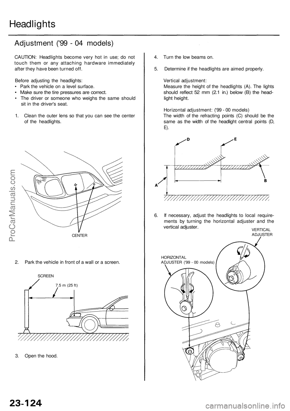
Headlights
Adjustmen t ('9 9 - 0 4 models )
CAUTION : Headlight s becom e ver y ho t i n use ; d o no t
touc h the m o r an y attachin g hardwar e immediatel y
afte r the y hav e bee n turne d off .
Befor e adjustin g th e headlights :
• Par k th e vehicl e o n a leve l surface .
• Mak e sur e th e tir e pressure s ar e correct .
• Th e drive r o r someon e who weigh s th e sam e shoul d
si t i n th e driver' s seat .
1 . Clea n th e oute r len s s o tha t yo u can see th e cente r
o f th e headlights . 4
. Tur n th e lo w beam s on .
5 . Determin e if th e headlight s ar e aime d properly .
Vertica l adjustment :
Measur e th e heigh t o f th e headlight s (A) . Th e light s
shoul d reflec t 5 2 m m (2. 1 in. ) belo w (B ) th e head -
light height .
Horizonta l adjustment : ('9 9 - 0 0 models )
Th e widt h o f th e refractin g point s (C ) shoul d b e th e
sam e a s th e widt h o f th e headligh t centra l point s (D ,
E).
2. Par k th e vehicl e in fron t o f a wal l o r a screen .
CENTER
SCREE N
3. Ope n th e hood .
7.5 m (2 5 ft )
6. I f necessary , adjus t th e headlight s t o loca l require -
ment s b y turnin g th e horizonta l adjuste r an d th e
vertica l adjuster .VERTICA LADJUSTE R
HORIZONTA L
ADJUSTE R ('9 9 - 0 0 models )
ProCarManuals.com