ACURA RL KA9 1996 Service Repair Manual
Manufacturer: ACURA, Model Year: 1996, Model line: RL KA9, Model: ACURA RL KA9 1996Pages: 1954, PDF Size: 61.44 MB
Page 1571 of 1954
Stereo Soun d Syste m
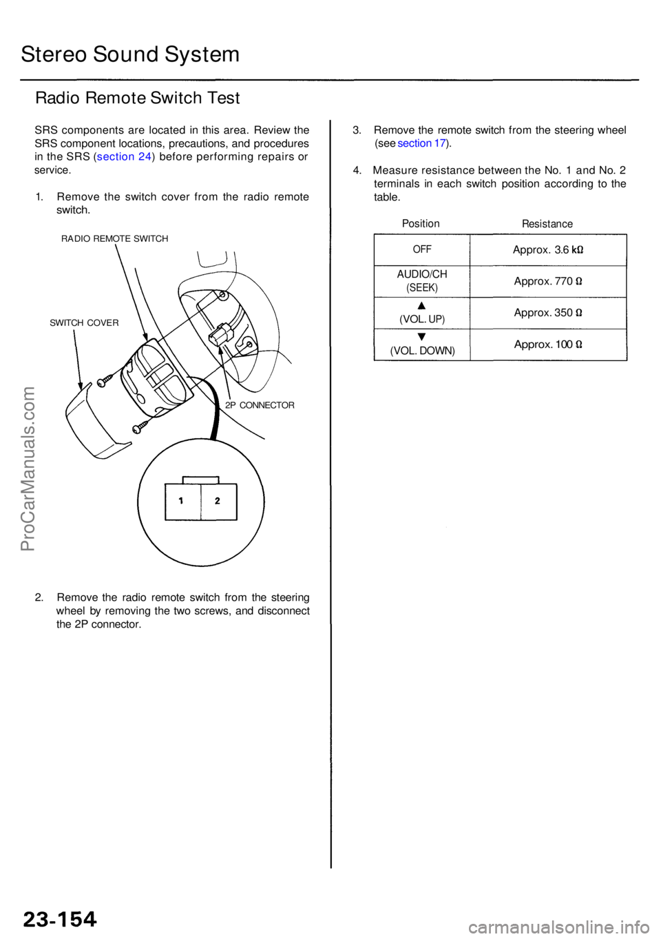
Radio Remot e Switc h Tes t
SRS component s ar e locate d i n thi s area . Revie w th e
SR S componen t locations , precautions , an d procedure s
i n th e SR S (sectio n 24 ) befor e performin g repair s o r
service .
1. Remov e th e switc h cove r fro m th e radi o remot e
switch.
RADIO REMOT E SWITC H
SWITC H COVE R
2P CONNECTO R
2. Remov e th e radi o remot e switc h fro m th e steerin g
whee l b y removin g th e tw o screws , an d disconnec t
th e 2 P connector . 3
. Remov e th e remot e switc h fro m th e steerin g whee l
(se e sectio n 17 ).
4 . Measur e resistanc e betwee n th e No . 1 an d No . 2
terminal s i n eac h switc h positio n accordin g t o th e
table .
Positio nResistanc e
Approx. 10 0
Approx . 35 0
Approx
. 77 0
Approx
. 3. 6
OF F
AUDIO/C H
(SEEK)
(VOL. UP)
(VOL . DOWN )
ProCarManuals.com
Page 1572 of 1954
Window Antenn a Wir e Tes t
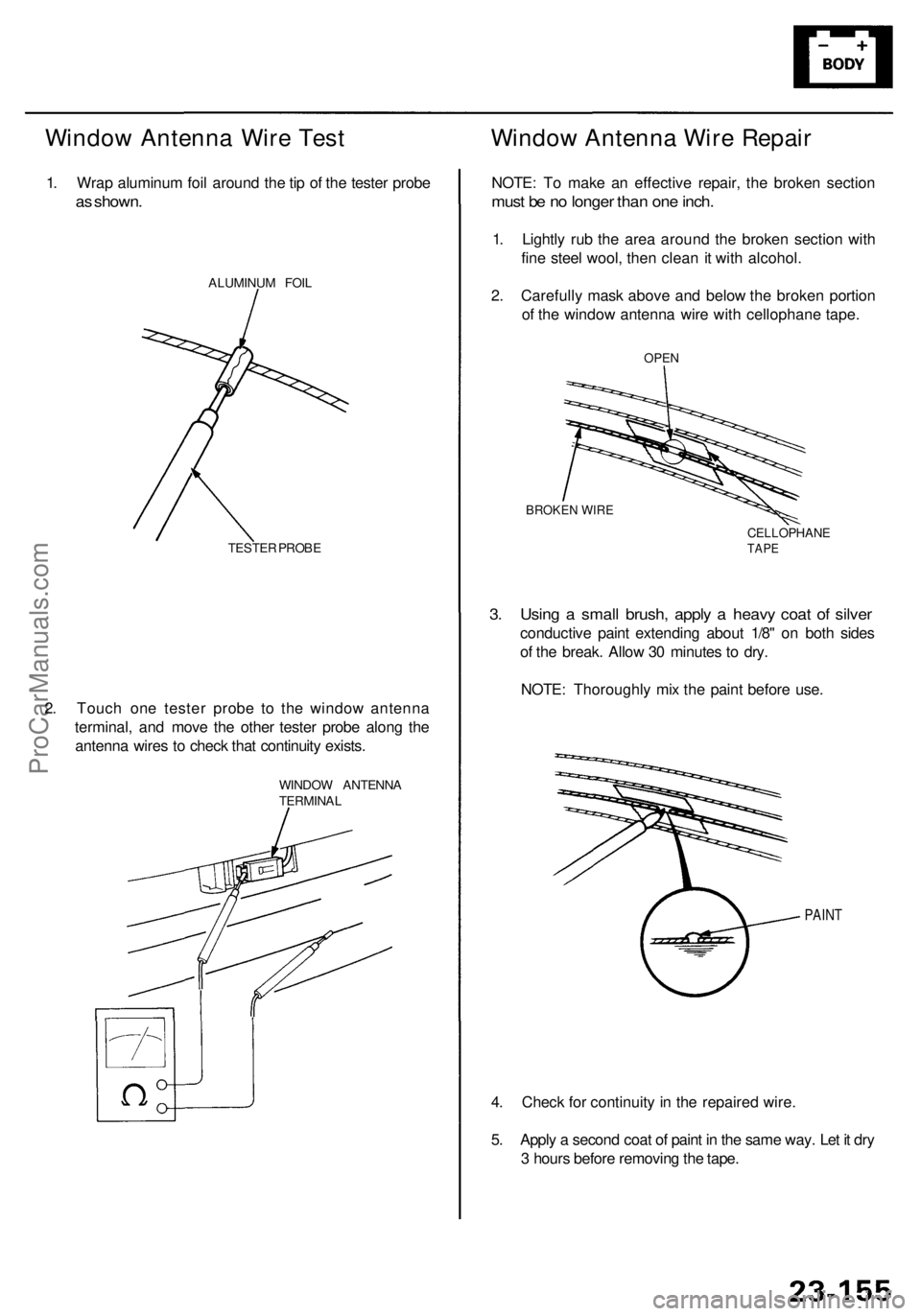
1. Wra p aluminu m foi l aroun d th e ti p o f th e teste r prob e
as shown .
ALUMINU M FOI L
TESTE R PROB E
2. Touc h on e teste r prob e t o th e windo w antenn a
terminal , an d mov e th e othe r teste r prob e alon g th e
antenn a wire s t o chec k tha t continuit y exists .
WINDO W ANTENN A
TERMINA L
Window Antenn a Wir e Repai r
NOTE: T o mak e a n effectiv e repair , th e broke n sectio n
must b e n o longe r tha n on e inch .
1. Lightl y ru b th e are a aroun d th e broke n sectio n wit h
fin e stee l wool , the n clea n it wit h alcohol .
2 . Carefull y mas k abov e an d belo w th e broke n portio n
o f th e windo w antenn a wir e wit h cellophan e tape .
4 . Chec k fo r continuit y i n th e repaire d wire .
5 . Appl y a secon d coa t o f pain t i n th e sam e way . Le t i t dr y
3 hour s befor e removin g th e tape .
PAIN T
3. Usin g a smal l brush , appl y a heav y coa t o f silve r
conductiv e pain t extendin g abou t 1/8 " o n bot h side s
o f th e break . Allo w 3 0 minute s t o dry .
NOTE : Thoroughl y mi x th e pain t befor e use .
BROKE N WIR E
CELLOPHAN ETAPE
OPE N
ProCarManuals.com
Page 1573 of 1954
Accessory Powe r Socke t
Replacemen t
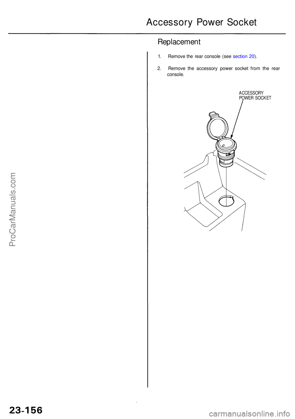
1. Remov e th e rea r consol e (se e sectio n 20 ).
2 . Remov e th e accessor y powe r socke t fro m th e rea r
console .
ACCESSOR Y
POWE R SOCKE T
ProCarManuals.com
Page 1574 of 1954
Cigarette Lighte r
Replacemen t
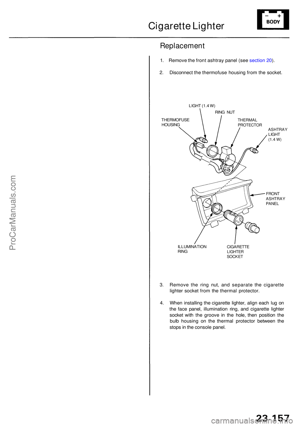
1. Remov e th e fron t ashtra y pane l (se e sectio n 20 ).
2 . Disconnec t th e thermofus e housin g fro m th e socket .
3 . Remov e th e rin g nut , an d separat e th e cigarett e
lighte r socke t fro m th e therma l protector .
4 . Whe n installin g th e cigarett e lighter , alig n eac h lu g o n
th e fac e panel , illuminatio n ring , an d cigarette lighter
socke t wit h th e groov e i n th e hole , the n positio n th e
bul b housin g o n th e therma l protecto r betwee n th e
stop s in th e consol e panel .
ILLUMINATIO N
RIN GCIGARETT ELIGHTERSOCKET
FRONTASHTRA YPANEL
ASHTRA YLIGHT(1.4 W )
THERMA LPROTECTO R
RING NU T
LIGH
T (1. 4 W )
THERMOFUS E
HOUSIN G
ProCarManuals.com
Page 1575 of 1954
Horns
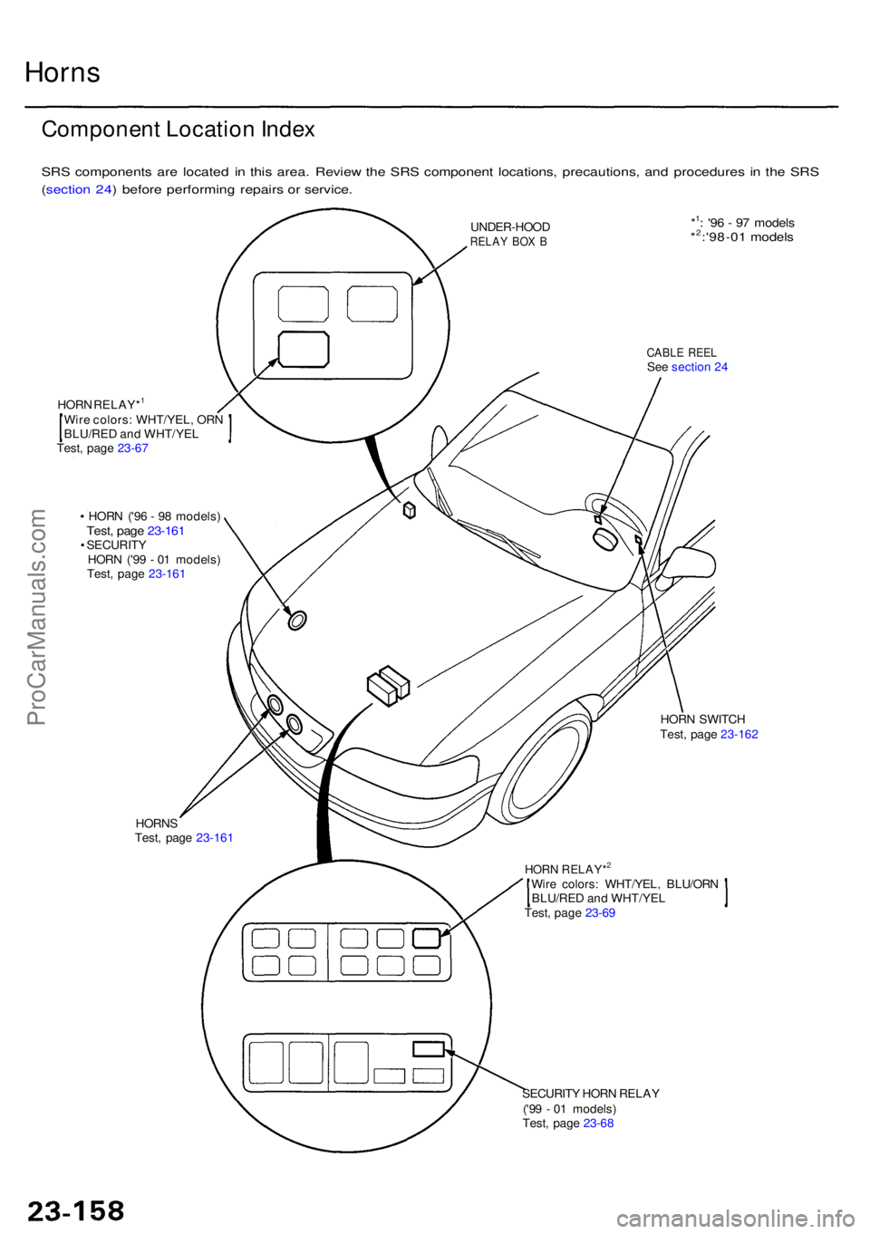
Componen t Locatio n Inde x
SRS component s ar e locate d i n thi s area . Revie w th e SR S componen t locations , precautions , an d procedure s i n th e SR S
( sectio n 24 ) befor e performin g repair s o r service .
CABLE REE LSee sectio n 2 4
UNDER-HOO
D
RELAY BO X B
Wir e colors : WHT/YEL , OR N
BLU/RE D an d WHT/YE L
Test , pag e 23-6 7
HOR
N RELAY*
1
• HOR N ('9 6 - 9 8 models )Test, pag e 23-161• SECURIT Y
HOR N ('9 9 - 0 1 models )
Test , pag e 23-161
HORN S
Test , pag e 23-161
SECURITY HOR N RELA Y
('9 9 - 0 1 models )
Test , pag e 23-6 8
Wir
e colors : WHT/YEL , BLU/OR N
BLU/RE D an d WHT/YE L
Test , pag e 23-6 9
HOR N RELAY*2
HOR N SWITC H
Test , pag e 23-162
*1: '9 6 - 9 7 model s*2:'98-01 model s
ProCarManuals.com
Page 1576 of 1954
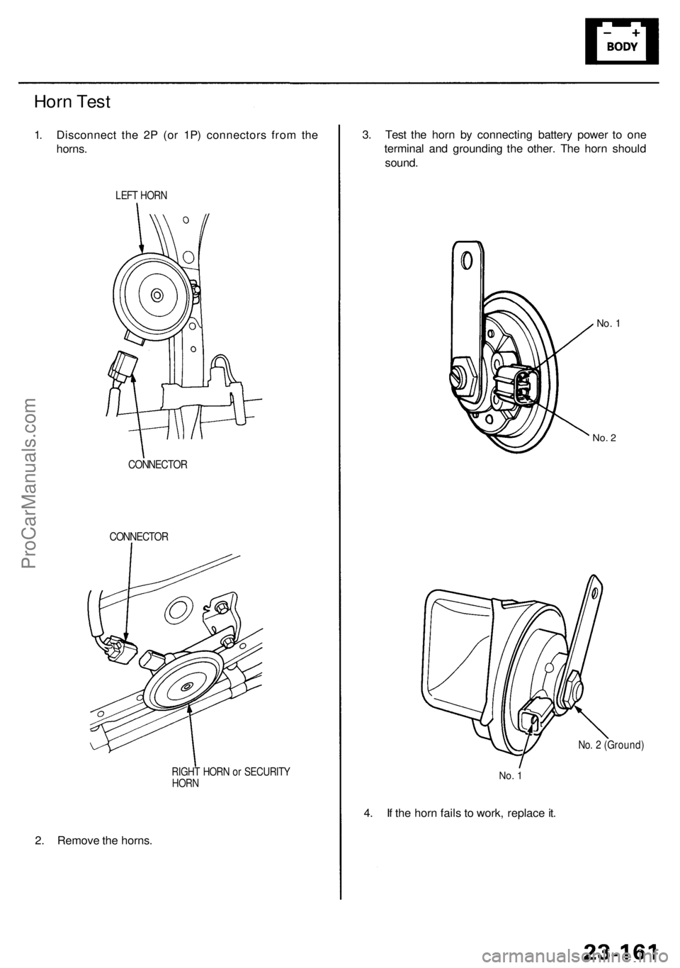
2. Remov e th e horns .
RIGHT HOR N o r SECURIT Y
HOR N
CONNECTO R
CONNECTO R
Horn Tes t
1. Disconnec t th e 2 P (o r 1P ) connector s fro m th e
horns .
LEFT HOR N
3. Tes t th e hor n b y connectin g batter y powe r t o on e
termina l an d groundin g th e other . Th e hor n shoul d
sound .
4 . I f th e hor n fail s t o work , replac e it .
No . 2 (Ground )
No. 1
No . 1
No . 2
ProCarManuals.com
Page 1577 of 1954
• I f ther e is continuity , th e hor n switc h i s OK .
• I f ther e is n o continuity , g o t o ste p 4 .
Horn s
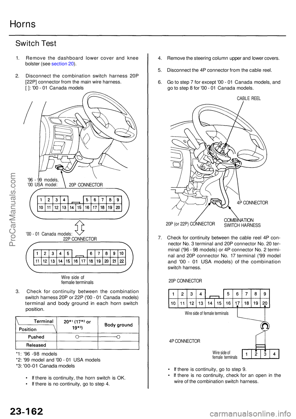
Switc h Tes t
1. Remov e th e dashboar d lowe r cove r an d kne e
bolste r (se e sectio n 20 ).
2 . Disconnec t th e combinatio n switc h harnes s 20 P
[22P ] connecto r fro m th e mai n wir e harness .
[ ] : '0 0 - 0 1 Canad a model s
20P CONNECTO R
'9
6 - 9 9 models ,
'0 0 US A model :
'0 0 - 0 1 Canad a models :
22 P CONNECTO R
Wir e sid e o f
femal e terminal s
3. Chec k fo r continuit y betwee n th e combinatio n
switc h harnes s 20 P o r 22 P ('0 0 - 0 1 Canad a models )
termina l an d bod y groun d i n eac h hor n switc h
position .
*1: '9 6 -9 8 model s
*2 : '9 9 mode l an d '0 0 - 0 1 US A model s
*3: '00-0 1 Canad a model s• I f ther e i s continuity , g o t o ste p 9 .
• I f ther e i s n o continuity , chec k fo r a n ope n i n th e
wir e o f th e combinatio n switc h harness .
Wire sid e o f
femal e terminal s
4P CONNECTO R
Wire sid e o f femal e terminal s
4. Remov e th e steerin g colum n uppe r an d lowe r covers .
5 . Disconnec t th e 4 P connecto r fro m th e cabl e reel .
6 . G o to ste p 7 fo r excep t '0 0 - 0 1 Canad a models , an d
g o to ste p 8 fo r '0 0 - 0 1 Canad a models .
CABLE REE L
4P CONNECTO R
COMBINATIO NSWITCH HARNES S
20
P (o r 22P ) CONNECTO R
7. Chec k fo r continuit y betwee n th e cabl e ree l 4 P con -
necto r No . 3 termina l an d 20 P connecto r No . 2 0 ter -
mina l ('9 6 - 9 8 models ) o r 4 P connecto r No . 2 termi -
na l an d 20 P connecto r No . 1 7 termina l ('9 9 mode l
and '0 0 - 0 1 US A models ) o f th e combinatio n
switch harness .
20P CONNECTO R
ProCarManuals.com
Page 1578 of 1954
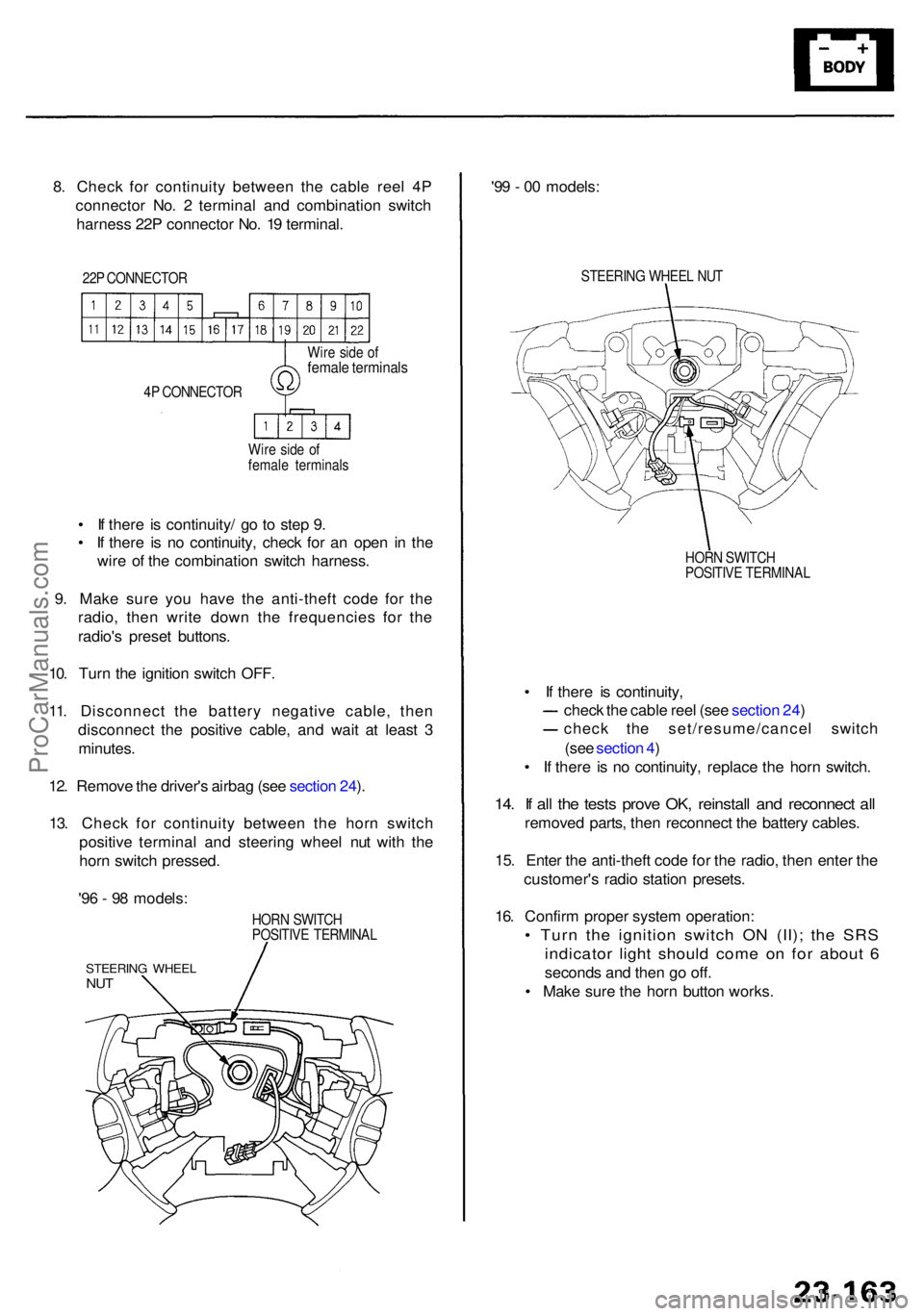
8. Chec k fo r continuit y betwee n th e cabl e ree l 4 P
connecto r No . 2 termina l an d combinatio n switc h
harnes s 22 P connecto r No . 1 9 terminal .
22P CONNECTO R
4 P CONNECTO R
Wir e sid e o f
femal e terminal s
Wir
e sid e o f
femal e terminal s
• I f ther e i s continuity / g o t o ste p 9 .
• I f ther e i s n o continuity , chec k fo r a n ope n i n th e
wir e o f th e combinatio n switc h harness .
9 . Mak e sur e yo u hav e th e anti-thef t cod e fo r th e
radio , the n writ e dow n th e frequencie s fo r th e
radio' s prese t buttons .
10 . Tur n th e ignitio n switc h OFF .
11 . Disconnec t th e batter y negativ e cable , the n
disconnec t th e positiv e cable , an d wai t a t leas t 3
minutes .
12 . Remov e th e driver' s airba g (se e sectio n 24 ).
13 . Chec k fo r continuit y betwee n th e hor n switc h
positiv e termina l an d steerin g whee l nu t wit h th e
hor n switc h pressed .
HORN SWITC H
POSITIV E TERMINA L
STEERING WHEE LNUT
'96 - 9 8 models : '9
9 - 0 0 models :
STEERIN G WHEE L NU T
HOR N SWITC H
POSITIV E TERMINA L
• I f ther e i s continuity ,
chec k th e cabl e ree l (se e sectio n 24 )
chec k th e set/resume/cance l switc h
(se e sectio n 4 )
• I f ther e i s n o continuity , replac e th e hor n switch .
14. I f al l th e test s prov e OK , reinstal l an d reconnec t al l
remove d parts , the n reconnec t th e batter y cables .
15 . Ente r th e anti-thef t cod e fo r th e radio , the n ente r th e
customer' s radi o statio n presets .
16 . Confir m prope r syste m operation :
• Tur n th e ignitio n switc h O N (II) ; th e SR S
indicato r ligh t shoul d com e o n fo r abou t 6
second s an d the n g o off .
• Mak e sur e th e hor n butto n works .
ProCarManuals.com
Page 1579 of 1954
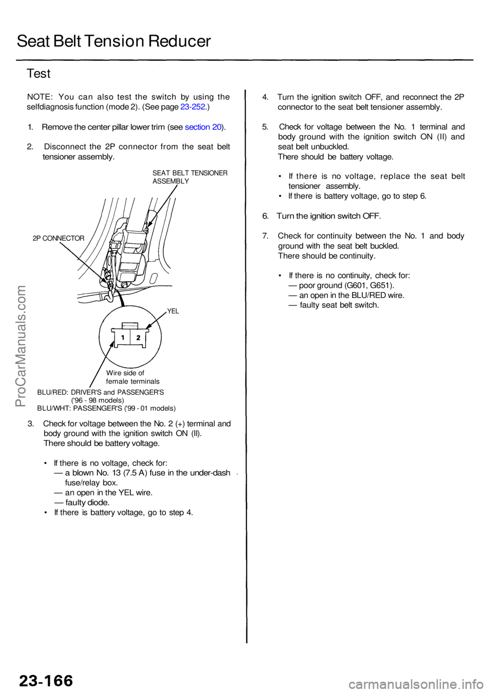
Seat Bel t Tensio n Reduce r
Test
NOTE : Yo u ca n als o tes t th e switc h b y usin g th e
selfdiagnosi s functio n (mod e 2) . (Se e pag e 23-252 .)
1 . Remov e th e cente r pilla r lowe r tri m (se e sectio n 20 ).
2 . Disconnec t th e 2 P connecto r fro m th e sea t bel t
tensione r assembly .
SEAT BEL T TENSIONE RASSEMBLY
2P CONNECTO R
YEL
4. Tur n th e ignitio n switc h OFF , an d reconnec t th e 2 P
connecto r t o th e sea t bel t tensione r assembly .
5 . Chec k fo r voltag e betwee n th e No . 1 termina l an d
bod y groun d wit h th e ignitio n switc h O N (II ) an d
sea t bel t unbuckled .
Ther e shoul d b e batter y voltage .
• I f ther e i s n o voltage , replac e th e sea t bel t
tensione r assembly .
• I f ther e is batter y voltage , g o to ste p 6 .
6. Tur n th e ignitio n switc h OFF .
7. Chec k fo r continuit y betwee n th e No . 1 an d bod y
groun d wit h th e sea t bel t buckled .
Ther e shoul d b e continuity .
• I f ther e is n o continuity , chec k for :
— poo r groun d (G601 , G651) .
— an ope n in th e BLU/RE D wire .
— fault y sea t bel t switch .
3 . Chec k fo r voltag e betwee n th e No . 2 (+ ) termina l an d
bod y groun d wit h th e ignitio n switc h O N (II) .
Ther e shoul d b e batter y voltage .
• I f ther e is n o voltage , chec k for :
— a blow n No . 1 3 (7. 5 A ) fus e in th e under-das h
fuse/relay box .
— an ope n in th e YE L wire .
— fault y diode .
• I f ther e i s batter y voltage , g o t o ste p 4 .
BLU/RED : DRIVER' S an d PASSENGER' S('96 - 9 8 models )
BLU/WHT : PASSENGER' S ('9 9 - 0 1 models )
Wir
e sid e o f
femal e terminal s
ProCarManuals.com
Page 1580 of 1954
Moonroof
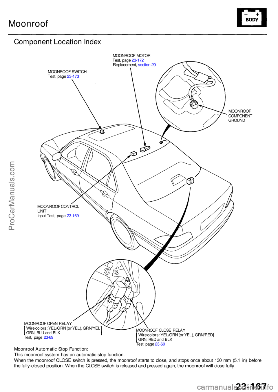
Componen t Locatio n Inde x
MOONROO F MOTO R
Test , pag e 23-17 2
Replacement , sectio n 2 0
MOONROO F SWITC H
Test , pag e 23-17 3
MOONROOF
COMPONEN T
GROUN D
MOONROO F CONTRO L
UNITInpu t Test , pag e 23-16 9
Moonroo f Automati c Sto p Function :
Thi s moonroo f syste m ha s a n automati c sto p function .
Whe n th e moonroo f CLOS E switc h is pressed , th e moonroo f start s t o close , an d stop s onc e abou t 13 0 m m (5. 1 in ) befor e
the fully-close d position. When the CLOS E switch is release d and presse d again, the moonroo f will clos e fully.
MOONROO F OPE N RELA Y
Wir e colors : YEL/GR N (o r YEL) , GRN/YE L
GRN, BLU an d BL KTest , pag e 23-6 9
MOONROO F CLOS E RELA YWire colors : YEL/GR N (o r YEL) , GRN/RED ]GRN, RED an d BL K Test , pag e 23-6 9
ProCarManuals.com