sensor ACURA RL KA9 1996 Service Repair Manual
[x] Cancel search | Manufacturer: ACURA, Model Year: 1996, Model line: RL KA9, Model: ACURA RL KA9 1996Pages: 1954, PDF Size: 61.44 MB
Page 1434 of 1954
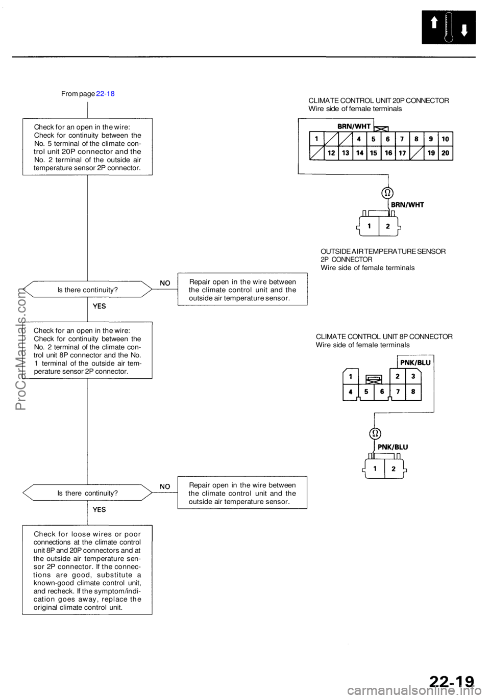
From pag e 22-1 8
CLIMATE CONTRO L UNI T 20 P CONNECTO R
Wire sid e o f femal e terminal s
Check fo r a n ope n in th e wire :
Chec k fo r continuit y betwee n th e
No . 5 termina l o f th e climat e con -
trol uni t 20 P connecto r an d th eNo . 2 termina l o f th e outsid e ai r
temperatur e senso r 2 P connector .
OUTSIDE AI R TEMPERATUR E SENSO R
2P CONNECTO RWire sid e o f femal e terminal s
I s ther e continuity ? Repai
r ope n in th e wir e betwee n
th e climat e contro l uni t an d th e
outsid e ai r temperatur e sensor .
Chec k fo r a n ope n in th e wire :
Chec k fo r continuit y betwee n th e
No . 2 termina l o f th e climat e con -
tro l uni t 8 P connecto r an d th e No .
1 termina l o f th e outsid e ai r tem -
peratur e senso r 2 P connector . CLIMAT
E CONTRO L UNI T 8 P CONNECTO R
Wir e sid e o f femal e terminal s
I s ther e continuity ? Repai
r ope n in th e wir e betwee n
th e climat e contro l uni t an d th e
outsid e ai r temperatur e sensor .
Chec k fo r loos e wire s o r poo r
connection s a t th e climat e contro l
uni t 8 P an d 20 P connector s an d a t
th e outsid e ai r temperatur e sen -
so r 2 P connector . I f th e connec -
tion s ar e good , substitut e a
known-goo d climat e contro l unit ,
an d recheck . I f th e symptom/indi -
catio n goe s away , replac e th e
origina l climat e contro l unit .
ProCarManuals.com
Page 1436 of 1954
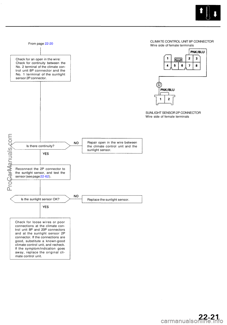
From pag e 22-2 0 CLIMAT
E CONTRO L UNI T 8 P CONNECTO R
Wir e sid e o f femal e terminal s
Chec k fo r a n ope n in th e wire :
Chec k fo r continuit y betwee n th e
No . 2 termina l o f th e climat e con -
trol uni t 8 P connecto r an d th eNo . 1 termina l o f th e sunligh tsensor 2 P connector .
SUNLIGHT SENSO R 2P CONNECTO R
Wir e sid e o f femal e terminal s
I s ther e continuity ? Repai
r ope n i n th e wir e betwee n
th e climat e contro l uni t an d th e
sunligh t sensor .
Reconnec t th e 2 P connecto r t o
th e sunligh t sensor , an d tes t th e
senso r (se e pag e 22-62 ).
I s th e sunligh t senso r OK ?
Replace th e sunligh t sensor .
Chec k fo r loos e wire s o r poo r
connection s a t th e climat e con -
tro l uni t 8 P an d 20 P connector s
an d a t th e sunligh t senso r 2 P
connector . I f th e connection s ar e
good , substitut e a known-goo d
climat e contro l unit , an d recheck .
I f th e symptom/indicatio n goe s
away , replac e th e origina l cli -
mat e contro l unit .
ProCarManuals.com
Page 1437 of 1954
Troubleshooting
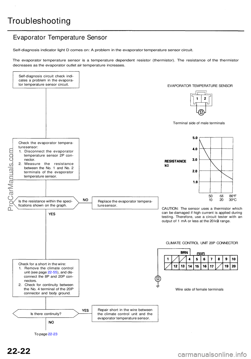
Evaporator Temperatur e Senso r
Self-diagnosi s indicato r ligh t D come s on : A proble m in th e evaporato r temperatur e senso r circuit .
The evaporato r temperatur e senso r i s a temperatur e dependen t resisto r (thermistor) . Th e resistanc e o f th e thermisto r
decreases a s th e evaporato r outle t ai r temperatur e increases .
Self-diagnosi s circui t chec k indi -
cate s a proble m in th e evapora -
to r temperatur e senso r circuit .
I s th e resistanc e withi n th e speci -
fication s show n o n th e graph .
Chec k fo r a shor t i n th e wire :
1 . Remov e th e climat e contro l
uni t (se e pag e 22-55 ), an d dis -
connec t th e 8 P an d 20 P con -
nectors .
2 . Chec k fo r continuit y betwee n
the No . 4 termina l o f th e 20 Pconnecto r an d bod y ground .
I s ther e continuity ?
T o pag e 22-2 3
EVAPORATO R TEMPERATUR E SENSO R
Termina l sid e o f mal e terminal s
Replac e th e evaporato r tempera -
tur e sensor .
5010682 086° F30°C
CAUTION : Th e senso r use s a thermisto r whic h
ca n b e damage d if hig h curren t i s applie d durin g
testing . Therefore , us e a circui t teste r wit h a n
outpu t o f 1 m A o r les s a t th e 2 0 k range .
CLIMAT E CONTRO L UNI T 20 P CONNECTO R
Wir e sid e o f femal e terminal s
Repai r shor t i n th e wir e betwee n
th e climat e contro l uni t an d th e
evaporato r temperatur e sensor .
Chec
k th e evaporato r tempera -
tur e sensor :
1 . Disconnec t th e evaporato r
temperatur e senso r 2 P con -
nector .
2 . Measur e th e resistanc e
betwee n th e No . 1 an d No . 2
terminal s o f th e evaporato r
temperatur e sensor .
ProCarManuals.com
Page 1438 of 1954
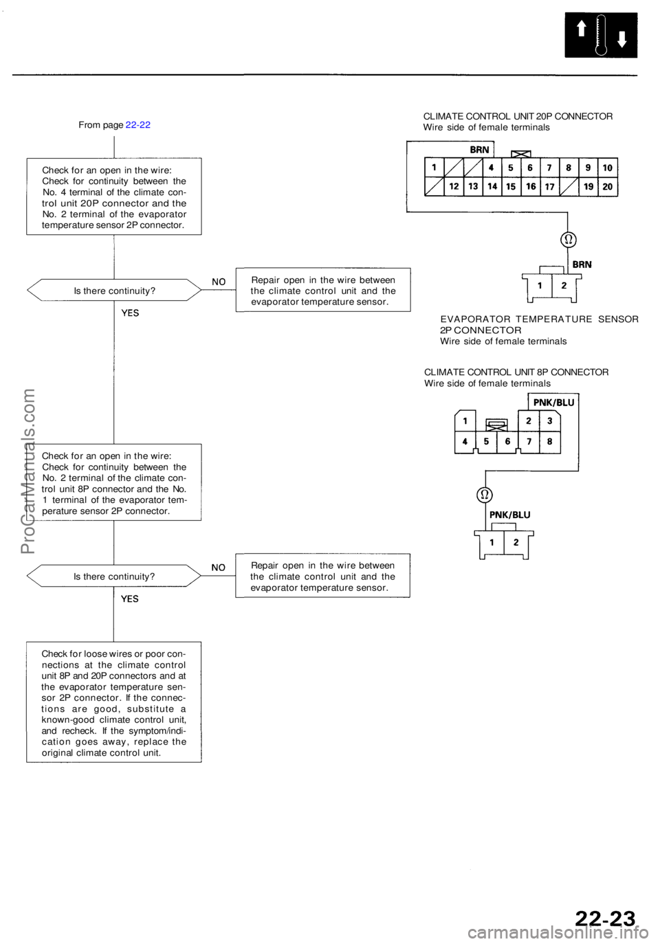
From pag e 22-2 2
Chec k fo r a n ope n in th e wire :
Chec k fo r continuit y betwee n th e
No . 4 termina l o f th e climat e con -
trol uni t 20 P connecto r an d th eNo . 2 termina l o f th e evaporato r
temperatur e senso r 2 P connector .
I s ther e continuity ?
Chec k fo r a n ope n in th e wire :
Chec k fo r continuit y betwee n th e
No . 2 termina l o f th e climat e con -
tro l uni t 8 P connecto r an d th e No .
1 termina l o f th e evaporato r tem -
peratur e senso r 2 P connector . CLIMAT
E CONTRO L UNI T 20 P CONNECTO R
Wir e sid e o f femal e terminal s
Repai r ope n i n th e wir e betwee n
th e climat e contro l uni t an d th e
evaporato r temperatur e sensor .
EVAPORATO R TEMPERATUR E SENSO R
2P CONNECTO RWire sid e o f femal e terminal s
CLIMAT E CONTRO L UNI T 8 P CONNECTO R
Wir e sid e o f femal e terminal s
I s ther e continuity ? Repai
r ope n i n th e wir e betwee n
th e climat e contro l uni t an d th e
evaporato r temperatur e sensor .
Chec k fo r loos e wire s o r poo r con -
nection s a t th e climat e contro l
uni t 8 P an d 20 P connector s an d a t
th e evaporato r temperatur e sen -
so r 2 P connector . I f th e connec -
tion s ar e good , substitut e a
known-goo d climat e contro l unit ,
an d recheck . I f th e symptom/indi -
catio n goe s away , replac e th e
origina l climat e contro l unit .
ProCarManuals.com
Page 1451 of 1954
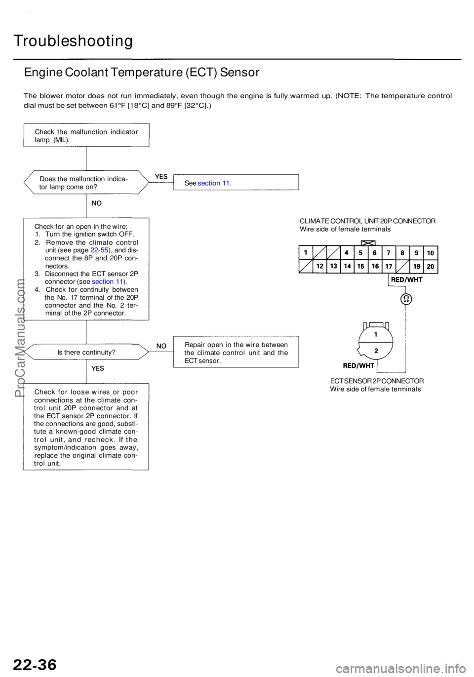
Troubleshooting
Engine Coolan t Temperatur e (ECT ) Senso r
The blowe r moto r doe s no t ru n immediately , eve n thoug h th e engin e is full y warme d up . (NOTE : Th e temperatur e contro l
dia l mus t b e se t betwee n 61° F [18°C ] an d 89° F [32°C]. )
Does th e malfunctio n indica -
to r lam p com e on ?
Chec k fo r a n ope n in th e wire :
1 . Tur n th e ignitio n switc h OFF .
2 . Remov e th e climat e contro l
uni t (se e pag e 22-55 ), an d dis -
connec t th e 8 P an d 20 P con -
nectors .
3 . Disconnec t th e EC T senso r 2 P
connecto r (se e sectio n 11 ).
4 . Chec k fo r continuit y betwee n
th e No . 1 7 termina l o f th e 20 P
connecto r an d th e No . 2 ter -
mina l o f th e 2 P connector .
I s ther e continuity ?
Chec k fo r loos e wire s o r poo r
connection s a t th e climat e con -trol uni t 20 P connecto r an d a t
th e EC T senso r 2 P connector . I f
th e connection s ar e good , substi -
tut e a known-goo d climat e con -
trol unit , an d recheck . I f th esymptom/indicatio n goe s away ,
replac e th e origina l climat e con -
tro l unit . Se
e sectio n 11 .
CLIMATE CONTRO L UNI T 20 P CONNECTO R
Wir e sid e o f femal e terminal s
Repai r ope n in th e wir e betwee n
th e climat e contro l uni t an d th e
EC T sensor .
ECT SENSO R 2P CONNECTO R
Wir e side of femal e terminal s
Chec
k th e malfunctio n indicato r
lam p (MIL) .
ProCarManuals.com
Page 1453 of 1954
Troubleshooting
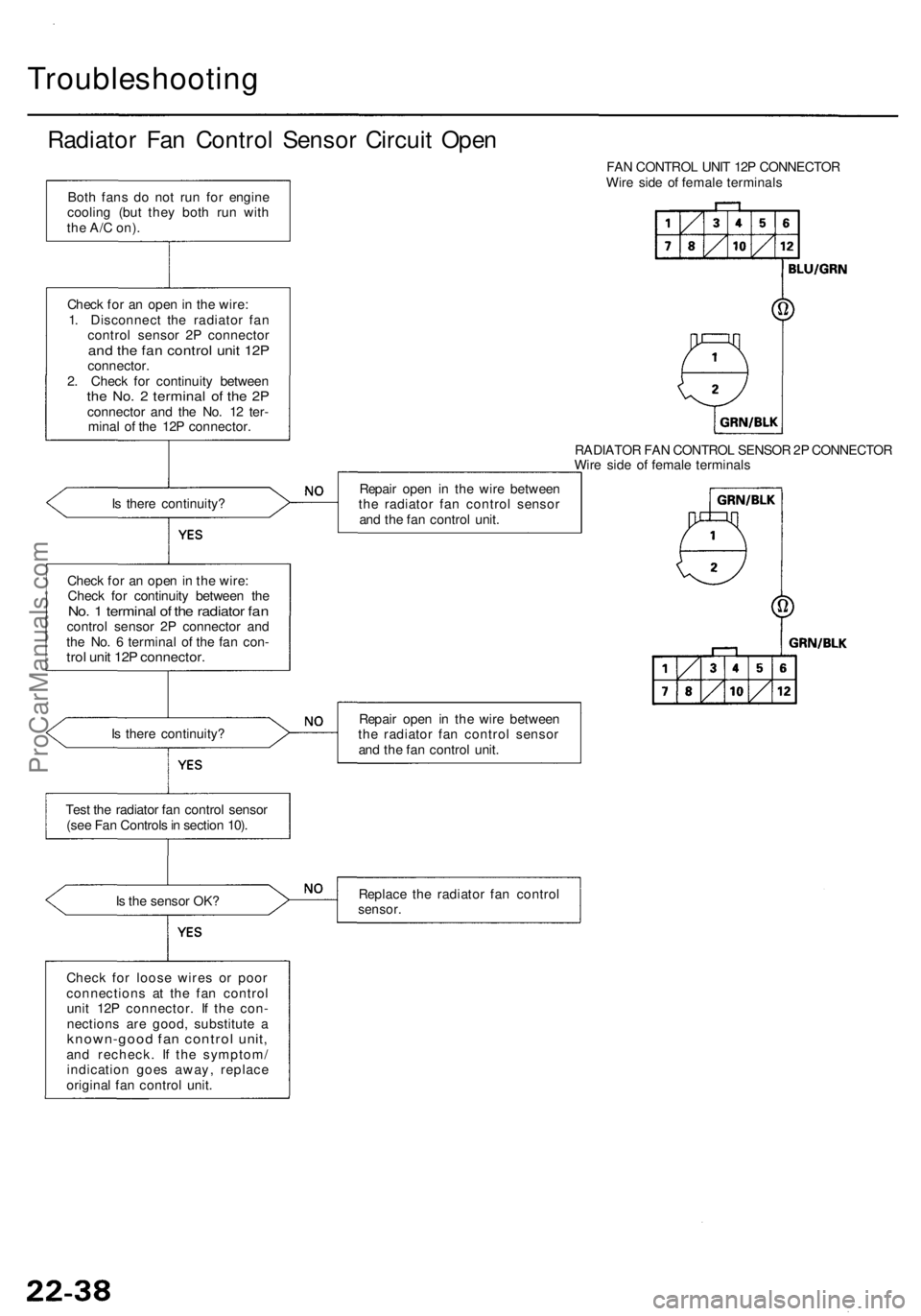
Radiator Fa n Contro l Senso r Circui t Ope n
Is ther e continuity ?
Chec k fo r a n ope n in th e wire :
Chec k fo r continuit y betwee n th e
No. 1 termina l o f th e radiato r fa ncontro l senso r 2 P connecto r an d
th e No . 6 termina l o f th e fa n con -
trol uni t 12 P connector .
Is ther e continuity ?
Tes t th e radiato r fa n contro l senso r
(se e Fa n Control s in sectio n 10) .
I s th e senso r OK ?
Chec k fo r loos e wire s o r poo r
connection s a t th e fa n contro l
uni t 12 P connector . I f th e con -
nection s ar e good , substitut e a
known-goo d fa n contro l unit ,and recheck . I f th e symptom /
indicatio n goe s away , replac e
origina l fa n contro l unit . FA
N CONTRO L UNI T 12 P CONNECTO R
Wir e sid e o f femal e terminal s
RADIATO R FA N CONTRO L SENSO R 2P CONNECTO R
Wir e sid e o f femal e terminal s
Repai r ope n i n th e wir e betwee n
th e radiato r fa n contro l senso r
an d th e fa n contro l unit .
Repai r ope n i n th e wir e betwee n
th e radiato r fa n contro l senso r
an d th e fa n contro l unit .
Replac e th e radiato r fa n contro l
sensor.
Both fan s d o no t ru n fo r engin e
coolin g (bu t the y bot h ru n wit h
the A/ C on) .
Chec k fo r a n ope n in th e wire :
1 . Disconnec t th e radiato r fa n
contro l senso r 2 P connecto r
and th e fa n contro l uni t 12 Pconnector .
2 . Chec k fo r continuit y betwee n
the No . 2 termina l o f th e 2 Pconnecto r an d th e No . 1 2 ter -
mina l o f th e 12 P connector .
ProCarManuals.com
Page 1454 of 1954
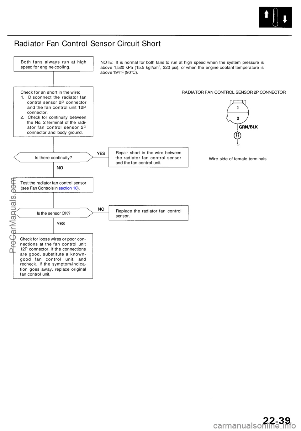
Radiator Fa n Contro l Senso r Circui t Shor t
NOTE : I t i s norma l fo r bot h fan s t o ru n a t hig h spee d whe n th e syste m pressur e i s
abov e 1,52 0 kP a (15. 5 kgf/cm2, 22 0 psi) , o r whe n th e engin e coolan t temperatur e i s
abov e 194° F (90°C) .
RADIATOR FA N CONTRO L SENSO R 2P CONNECTO R
I s ther e continuity ? Repai
r shor t i n th e wir e betwee n
th e radiato r fa n contro l senso r
an d th e fa n contro l unit . Wir
e sid e o f femal e terminal s
Tes t th e radiato r fa n contro l senso r
(se e Fa n Control s in sectio n 10 ).
I s th e senso r OK ? Replac
e th e radiato r fa n contro l
sensor.
Check fo r loos e wire s o r poo r con -
nection s a t th e fa n contro l uni t
12 P connector . I f th e connection s
ar e good , substitut e a known -
goo d fa n contro l unit , an d
recheck . I f th e symptom/indica -
tio n goe s away , replac e origina l
fa n contro l unit .
Chec
k fo r a n shor t i n th e wire :
1 . Disconnec t th e radiato r fa n
contro l senso r 2 P connecto r
and th e fa n contro l uni t 12 Pconnector .
2 . Chec k fo r continuit y betwee n
th e No . 2 termina l o f th e radi -
ato r fa n contro l senso r 2 P
connecto r an d bod y ground .
Bot
h fan s alway s ru n a t hig h
spee d fo r engin e cooling .
ProCarManuals.com
Page 1466 of 1954
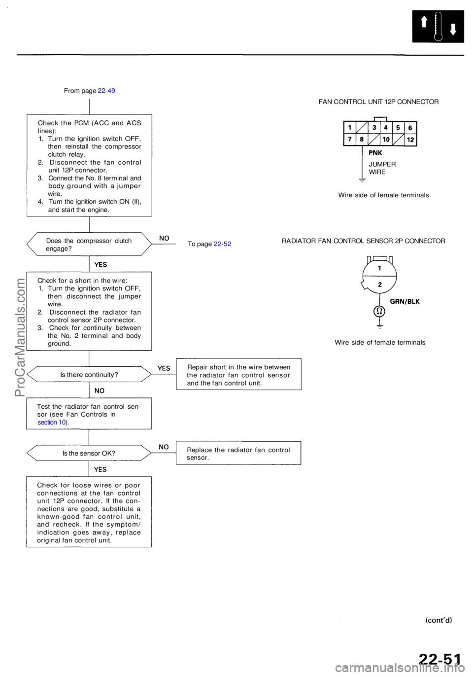
From pag e 22-4 9
Chec k th e PC M (AC C an d AC S
lines) :1. Tur n th e ignitio n switc h OFF ,then reinstal l th e compresso r
clutc h relay .
2 . Disconnec t th e fa n contro l
uni t 12 P connector .
3 . Connec t th e No . 8 termina l an d
bod y groun d wit h a jumpe rwire.
4 . Tur n th e ignitio n switc h O N (II) ,
an d star t th e engine .
Doe s th e compresso r clutc h
engage ?
Is ther e continuity ?
Test th e radiato r fa n contro l sen -
so r (se e Fa n Control s i n
section 10 ).
Is th e senso r OK ?
Chec k fo r loos e wire s o r poo r
connection s a t th e fa n contro l
uni t 12 P connector . I f th e con -
nection s ar e good , substitut e a
known-goo d fa n contro l unit ,
an d recheck . I f th e symptom /
indicatio n goe s away , replac e
origina l fa n contro l unit . FA
N CONTRO L UNI T 12 P CONNECTO R
T o pag e 22-5 2 Wir
e sid e o f femal e terminal s
RADIATO R FA N CONTRO L SENSO R 2 P CONNECTO R
Wir e sid e o f femal e terminal s
Repai r shor t i n th e wir e betwee n
th e radiato r fa n contro l senso r
an d th e fa n contro l unit .
Replac e th e radiato r fa n contro lsensor.
Check fo r a shor t i n th e wire :1. Tur n th e ignitio n switc h OFF ,then disconnec t th e jumpe rwire.2. Disconnec t th e radiato r fa n
contro l senso r 2 P connector .
3 . Chec k fo r continuit y betwee n
th e No . 2 termina l an d bod y
ground . JUMPE
R
WIRE
ProCarManuals.com
Page 1476 of 1954
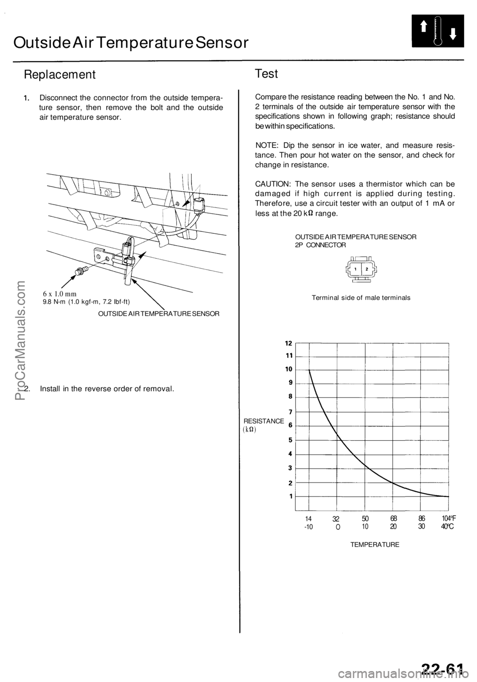
Outside Ai r Temperatur e Senso r
Replacemen t
Disconnect th e connecto r fro m th e outsid e tempera -
tur e sensor , the n remov e th e bol t an d th e outsid e
ai r temperatur e sensor .
6 x 1. 0 m m9.8 N- m (1. 0 kgf-m , 7. 2 Ibf-ft )
OUTSID E AI R TEMPERATUR E SENSO R
2. Instal l i n th e revers e orde r o f removal .
Test
Compar e th e resistanc e readin g betwee n th e No . 1 an d No .
2 terminal s o f th e outsid e ai r temperatur e senso r wit h th e
specification s show n i n followin g graph ; resistanc e shoul d
be withi n specifications .
NOTE: Di p th e senso r i n ic e water , an d measur e resis -
tance . The n pou r ho t wate r o n th e sensor , an d chec k fo r
chang e in resistance .
CAUTION : Th e senso r use s a thermisto r whic h ca n b e
damage d i f hig h curren t i s applie d durin g testing .
Therefore , us e a circui t teste r wit h a n outpu t o f 1 m A o r
les s a t th e 2 0 k range .
OUTSIDE AI R TEMPERATUR E SENSO R
2 P CONNECTO R
Termina l sid e o f mal e terminal s
RESISTANC E(k )
14-1 032O501 0682 0863 0104° F40°C
TEMPERATUR E
ProCarManuals.com
Page 1477 of 1954
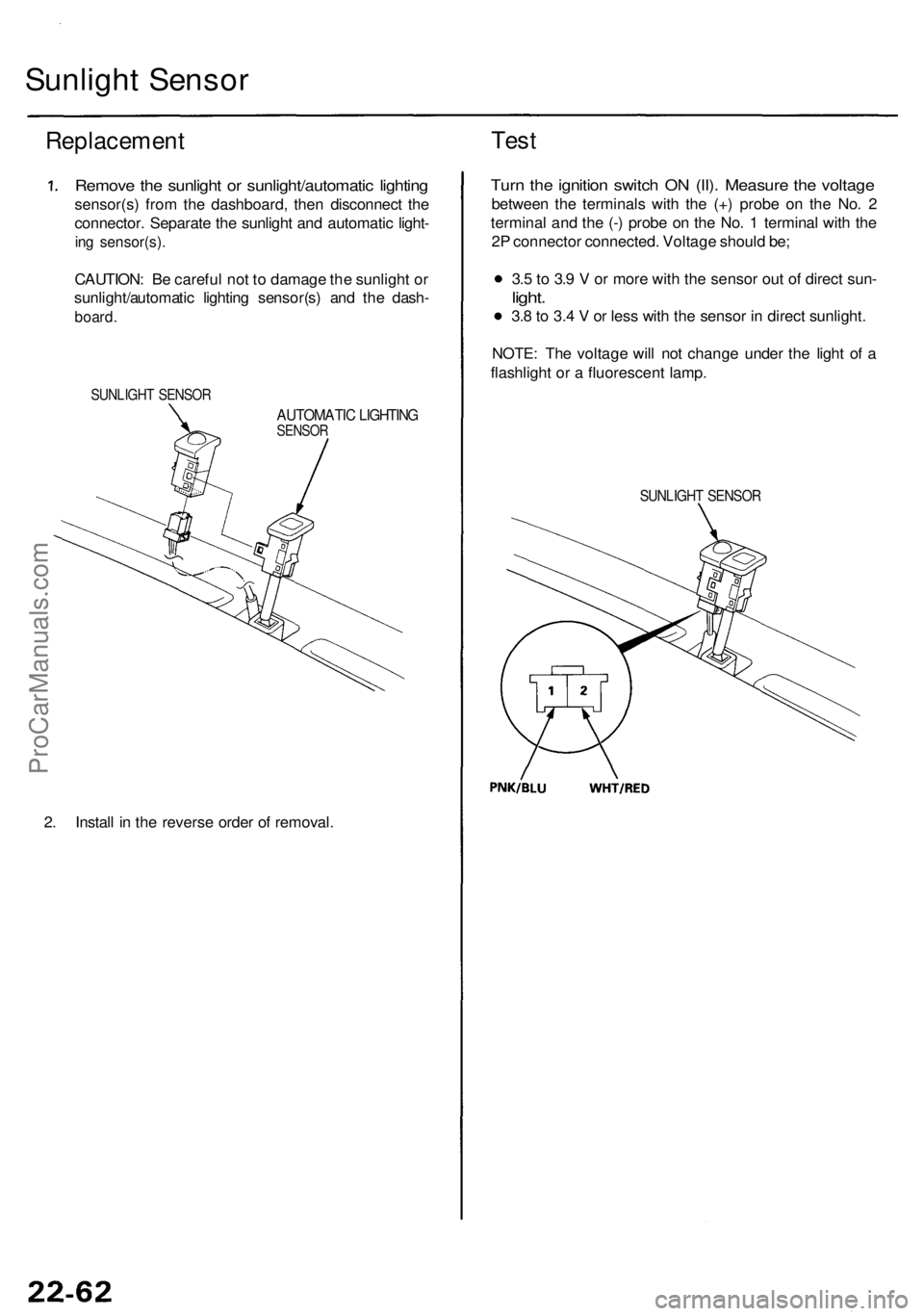
Sunlight Senso r
Replacemen t
Remove th e sunligh t o r sunlight/automati c lightin g
sensor(s ) fro m th e dashboard , the n disconnec t th e
connector . Separat e th e sunligh t an d automati c light -
ing sensor(s) .
CAUTION: B e carefu l no t t o damag e th e sunligh t o r
sunlight/automati c lightin g sensor(s ) an d th e dash -
board .
SUNLIGH T SENSO R
AUTOMATI C LIGHTIN GSENSOR
2. Instal l i n th e revers e orde r o f removal .
Test
Turn th e ignitio n switc h O N (II) . Measur e th e voltag e
betwee n th e terminal s wit h th e (+ ) prob e o n th e No . 2
termina l an d th e (- ) prob e o n th e No . 1 termina l wit h th e
2 P connecto r connected . Voltag e shoul d be ;
3. 5 to 3. 9 V or mor e wit h th e senso r ou t o f direc t sun -
light.
3.8 to 3. 4 V or les s wit h th e senso r i n direc t sunlight .
NOTE : Th e voltag e wil l no t chang e unde r th e ligh t o f a
flashligh t o r a fluorescen t lamp .
SUNLIGH T SENSO R
ProCarManuals.com