brake ACURA RL KA9 1996 Service Owner's Manual
[x] Cancel search | Manufacturer: ACURA, Model Year: 1996, Model line: RL KA9, Model: ACURA RL KA9 1996Pages: 1954, PDF Size: 61.44 MB
Page 819 of 1954
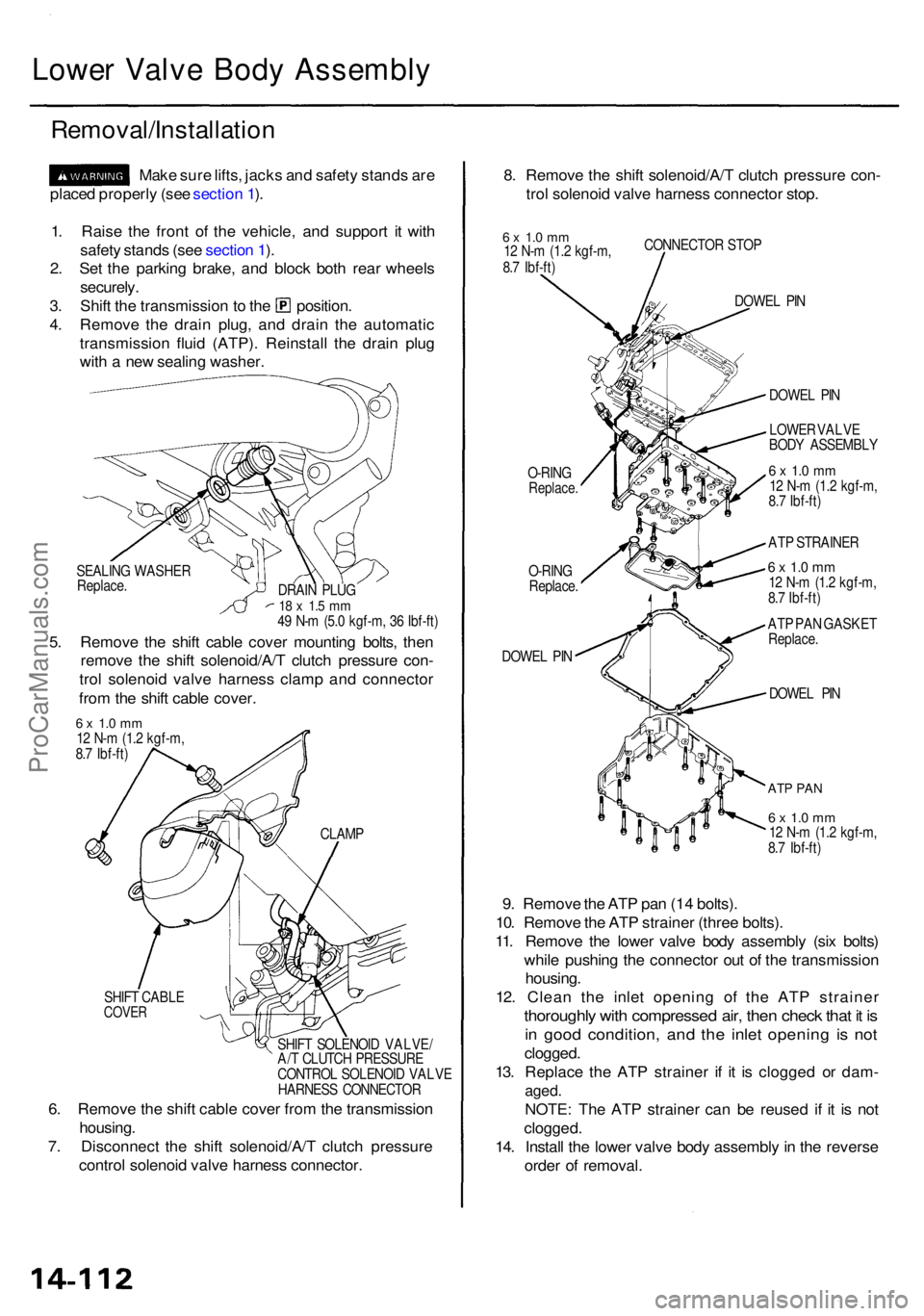
Lower Valv e Bod y Assembl y
Removal/Installatio n
Make sur e lifts , jack s an d safet y stand s ar e
place d properl y (se e sectio n 1 ).
1 . Rais e th e fron t o f th e vehicle , an d suppor t i t wit h
safet y stand s (se e sectio n 1 ).
2 . Se t th e parkin g brake , an d bloc k bot h rea r wheel s
securely .
3. Shif t th e transmissio n to th e position .
4 . Remov e th e drai n plug , an d drai n th e automati c
transmissio n flui d (ATP) . Reinstal l th e drai n plu g
wit h a ne w sealin g washer . 8
. Remov e th e shif t solenoid/A/ T clutc h pressur e con -
tro l solenoi d valv e harnes s connecto r stop .
6 x 1. 0 m m12 N- m (1. 2 kgf-m ,
8. 7 Ibf-ft ) CONNECTO
R STO P
O-RIN G
Replace .
O-RING
Replace .
DOWE L PI N DOWE
L PI N
DOWE L PI N
ATP PA N
6 x 1. 0 m m12 N- m (1. 2 kgf-m ,
8. 7 Ibf-ft )
9. Remov e th e AT P pa n (1 4 bolts) .
10 . Remov e th e AT P straine r (thre e bolts) .
11 . Remov e th e lowe r valv e bod y assembl y (si x bolts )
whil e pushin g th e connecto r ou t o f th e transmissio n
housing .
12 . Clea n th e inle t openin g o f th e AT P straine r
thoroughly wit h compresse d air , the n chec k tha t i t i s
in goo d condition , an d th e inle t openin g i s no t
clogged .
13 . Replac e th e AT P straine r i f i t i s clogge d o r dam -
aged.
NOTE : Th e AT P straine r ca n b e reuse d i f i t i s no t
clogged .
14. Instal l th e lowe r valv e bod y assembl y in th e revers e
orde r o f removal .
SEALING WASHE R
Replace .
5. Remov e th e shif t cabl e cove r mountin g bolts , the n
remov e th e shif t solenoid/A/ T clutc h pressur e con -
tro l solenoi d valv e harnes s clam p an d connecto r
fro m th e shif t cabl e cover .
DRAIN PLU G18 x 1. 5 m m49 N- m (5. 0 kgf-m , 3 6 Ibf-ft ) DOWE
L PI N
LOWE R VALV E
BOD Y ASSEMBL Y
6 x 1. 0 m m12 N- m (1. 2 kgf-m ,
8. 7 Ibf-ft )
AT P STRAINE R
6 x 1. 0 m m12 N- m (1. 2 kgf-m ,
8. 7 Ibf-ft )
AT P PA N GASKE T
Replace .
6 x 1. 0 m m12 N- m (1. 2 kgf-m ,
8. 7 Ibf-ft )
SHIF T CABL E
COVER
SHIFT SOLENOI D VALVE /
A/ T CLUTC H PRESSUR E
CONTRO L SOLENOI D VALV E
HARNES S CONNECTO R
CLAM
P
6. Remov e th e shif t cabl e cove r fro m th e transmissio n
housing .
7 . Disconnec t th e shif t solenoid/A/ T clutc h pressur e
contro l solenoi d valv e harnes s connector .
ProCarManuals.com
Page 903 of 1954
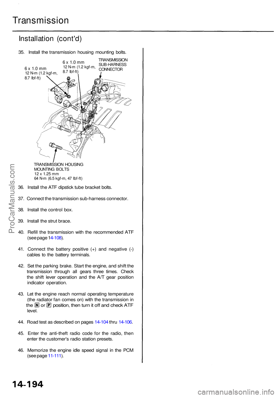
Transmission
Installation (cont'd )
TRANSMISSIO N HOUSIN GMOUNTIN G BOLT S12 x 1.2 5 m m64 N- m (6. 5 kgf-m , 4 7 Ibf-ft )
36. Instal l th e AT F dipstic k tub e bracke t bolts .
37 . Connec t th e transmissio n sub-harnes s connector .
38 . Instal l th e contro l box .
39 . Instal l th e stru t brace .
40 . Refil l th e transmissio n wit h th e recommende d AT F
(se e pag e 1 4-108 ).
41 . Connec t th e batter y positiv e (+ ) an d negativ e (- )
cable s t o th e batter y terminals .
42 . Se t th e parkin g brake . Star t th e engine , an d shif t th e
transmissio n throug h al l gear s thre e times . Chec k
th e shif t leve r operatio n an d th e A/ T gea r positio n
indicato r operation .
43 . Le t th e engin e reac h norma l operatin g temperatur e
(th e radiato r fa n come s on ) wit h th e transmissio n in
th e o r position , the n tur n it of f an d chec k AT F
level .
44 . Roa d tes t a s describe d o n page s 14-10 4 thr u 14-106 .
45 . Ente r th e anti-thef t radi o cod e fo r th e radio , the n
ente r th e customer' s radi o statio n presets .
46 . Memoriz e th e engin e idl e spee d signa l i n th e PC M
(se e pag e 11-111 ).
35
. Instal l th e transmissio n housin g mountin g bolts .
TRANSMISSIO NSUB-HARNES SCONNECTOR
6 x 1. 0 m m12 N- m (1. 2 kgf-m ,8.7 Ibf-ft )6 x 1. 0 m m12 N- m (1. 2 kgf-m ,8.7 Ibf-ft )
ProCarManuals.com
Page 909 of 1954
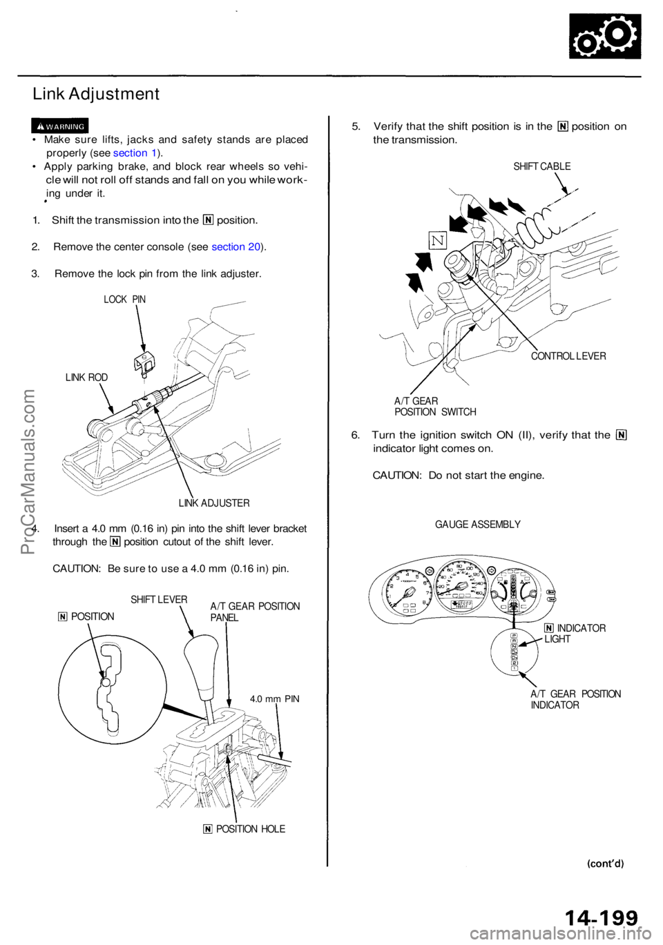
Link Adjustmen t
• Mak e sur e lifts , jack s an d safet y stand s ar e place d
properl y (se e sectio n 1 ).
• Appl y parkin g
brake, and bloc k rea r wheel s s o vehi -
cle wil l no t rol l of f stand s an d fal l o n yo u whil e work -
ing unde r it .
1. Shif t the transmissio n into the position .
2. Remov e th e cente r consol e (se e sectio n 20 ).
3 . Remov e th e loc k pi n fro m th e lin k adjuster .
LINK RO D
LINK ADJUSTE R
4. Inser t a 4. 0 m m (0.1 6 in ) pi n int o th e shif t leve r bracke t
through th e positio n cutou t o f th e shif t lever .
CAUTION : B e sur e t o us e a 4. 0 m m (0.1 6 in ) pin .
SHIF T LEVE R
POSITIO NA/T GEA R POSITIO N
PANE L
POSITIO N HOL E
5. Verif y tha t th e shif t positio n is i n th e positio n o n
the transmission .
SHIFT CABL E
CONTRO L LEVE R
A/ T GEA R
POSITIO N SWITC H
6. Tur n th e ignitio n switc h O N (II) , verif y tha t th e
indicato r ligh t come s on .
CAUTION : D o no t star t th e engine .
GAUGE ASSEMBL Y
INDICATOR
LIGH T
A/ T GEA R POSITIO N
INDICATO R
LOCK PI N
4.0 m m PI N
ProCarManuals.com
Page 911 of 1954
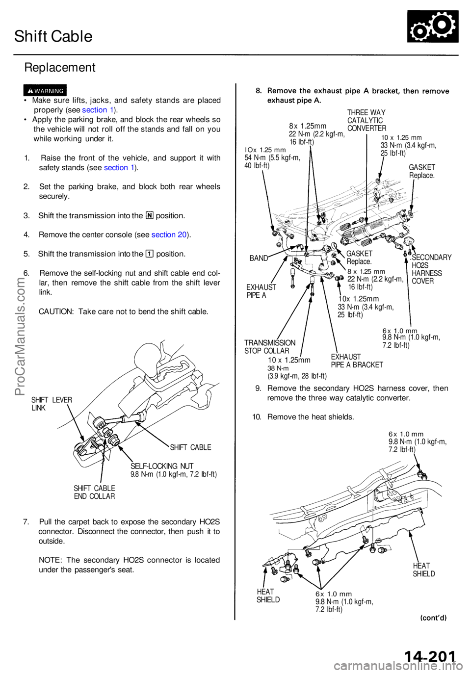
Shift Cabl e
Replacemen t
• Mak e sur e lifts , jacks , an d safet y stand s ar e place d
properl y (se e sectio n
1).
• Appl y th e parkin g brake , an d bloc k th e rea r wheel s s o
th e vehicl e wil l no t rol l of f th e stand s an d fal l o n yo u
whil e workin g unde r it .
1 . Rais e th e fron t o f th e vehicle , an d suppor t i t wit h
safet y stand s (se e sectio n
1).
2 . Se t th e parkin g brake , an d bloc k bot h rea r wheel s
securely .
3. Shif t th e transmissio n int o th e position .
4. Remov e th e cente r consol e (se e sectio n 20 ).
5 . Shif t th e transmissio n int o th e position .
6. Remov e th e self-lockin g nu t an d shif t cabl e en d col -
lar , the n remov e th e shif t cabl e fro m th e shif t leve r
link .
CAUTION : Tak e car e no t t o ben d th e shif t cable .
SHIFT LEVE RLINK
SHIF T CABL E
SELF-LOCKIN G NU T9.8 N- m (1. 0 kgf-m , 7.2 Ibf-ft )
SHIFT CABL E
EN D COLLA R
7. Pul l th e carpe t bac k t o expos e th e secondar y HO2 S
connector . Disconnec t th e connector , the n pus h i t t o
outside .
NOTE : Th e secondar y HO2 S connecto r i s locate d
unde r th e passenger' s seat .
BAND
EXHAUS TPIPE A
TRANSMISSIO NSTOP COLLA R
10 x 1.25m m38 N- m(3.9 kgf-m , 28 Ibf-ft )
SECONDAR Y
HO2 S
HARNES S
COVE R
6x 1. 0 m m9.8 N- m (1. 0 kgf-m ,7.2 Ibf-ft )
EXHAUS T
PIP E A BRACKE T
9. Remov e th e secondar y HO2 S harnes s cover , the n
remov e th e thre e wa y catalyti c converter .
10 . Remov e th e hea t shields .
6x 1. 0 m m9.8 N- m (1. 0 kgf-m ,7.2 Ibf-ft )
HEATSHIEL D6x 1.0 m m9.8 N- m (1. 0 kgf-m ,7.2 Ibf-ft )
HEAT
SHIEL D
8x 1.25m m22 N- m (2. 2 kgf-m ,16 Ibf-ft )
THRE E WA Y
CATALYTI C
CONVERTE R
10 x 1.2 5 mm33 N- m (3. 4 kgf-m ,25 Ibf-ft )
GASKE TReplace .
lOx 1.2 5 mm54 N- m (5. 5 kgf-m ,40 Ibf-ft )
GASKE T
Replace .
8 x 1.2 5 mm22 N- m (2. 2 kgf-m ,16 Ibf-ft )
10x 1.25m m33 N- m (3. 4 kgf-m ,25 Ibf-ft )
ProCarManuals.com
Page 1027 of 1954
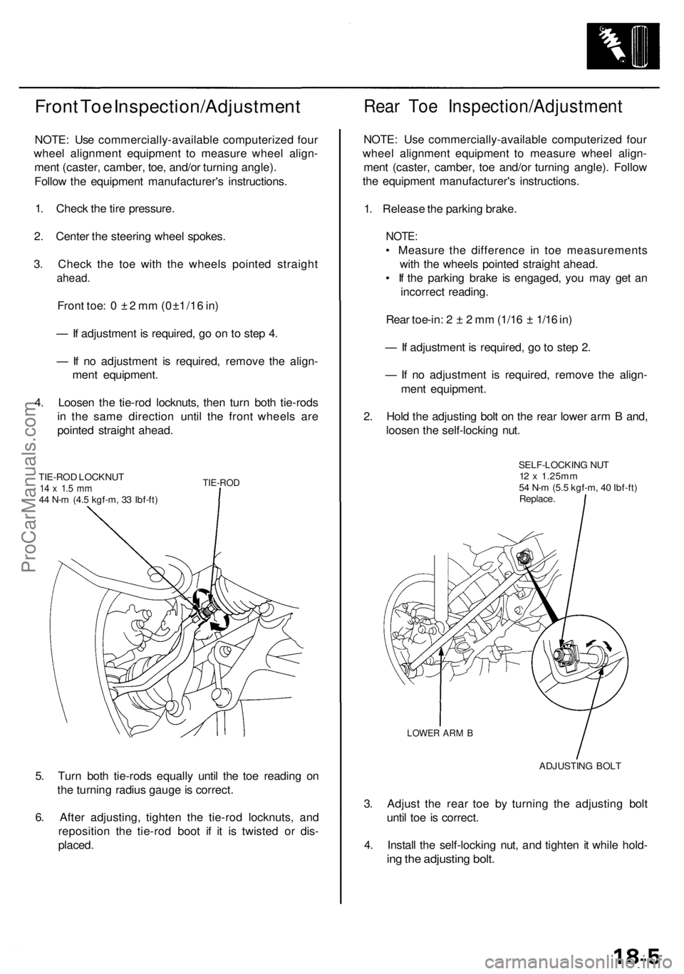
Front Toe Inspection/Adjustment
NOTE: Use commercially-available computerized four
wheel alignment equipment to measure wheel align-
ment (caster, camber, toe, and/or turning angle).
Follow the equipment manufacturer's instructions.
1. Check the tire pressure.
2. Center the steering wheel spokes.
3. Check the toe with the wheels pointed straight
ahead.
Front toe: 0 ± 2 mm (0±1/16 in)
— If adjustment is required, go on to step 4.
— If no adjustment is required, remove the align-
ment equipment.
4. Loosen the tie-rod locknuts, then turn both tie-rods
in the same direction until the front wheels are
pointed straight ahead.
TIE-ROD LOCKNUT
14 x 1.5 mm
44 N-m (4.5 kgf-m, 33 Ibf-ft)
TIE-ROD
5. Turn both tie-rods equally until the toe reading on
the turning radius gauge is correct.
6. After adjusting, tighten the tie-rod locknuts, and
reposition the tie-rod boot if it is twisted or dis-
placed.
Rear Toe Inspection/Adjustment
NOTE: Use commercially-available computerized four
wheel alignment equipment to measure wheel align-
ment (caster, camber, toe and/or turning angle). Follow
the equipment manufacturer's instructions.
1. Release the parking brake.
NOTE:
• Measure the difference in toe measurements
with the wheels pointed straight ahead.
• If the parking brake is engaged, you may get an
incorrect reading.
Rear toe-in: 2 ± 2 mm (1/16 ± 1/16 in)
— If adjustment is required, go to step 2.
— If no adjustment is required, remove the align-
ment equipment.
2. Hold the adjusting bolt on the rear lower arm B and,
loosen the self-locking nut.
SELF-LOCKING NUT
12 x 1.25mm
54 N-m (5.5 kgf-m, 40 Ibf-ft)
Replace.
LOWER ARM B
ADJUSTING BOLT
3. Adjust the rear toe by turning the adjusting bolt
until toe is correct.
4. Install the self-locking nut, and tighten it while hold-
ing the adjusting bolt.ProCarManuals.com
Page 1028 of 1954
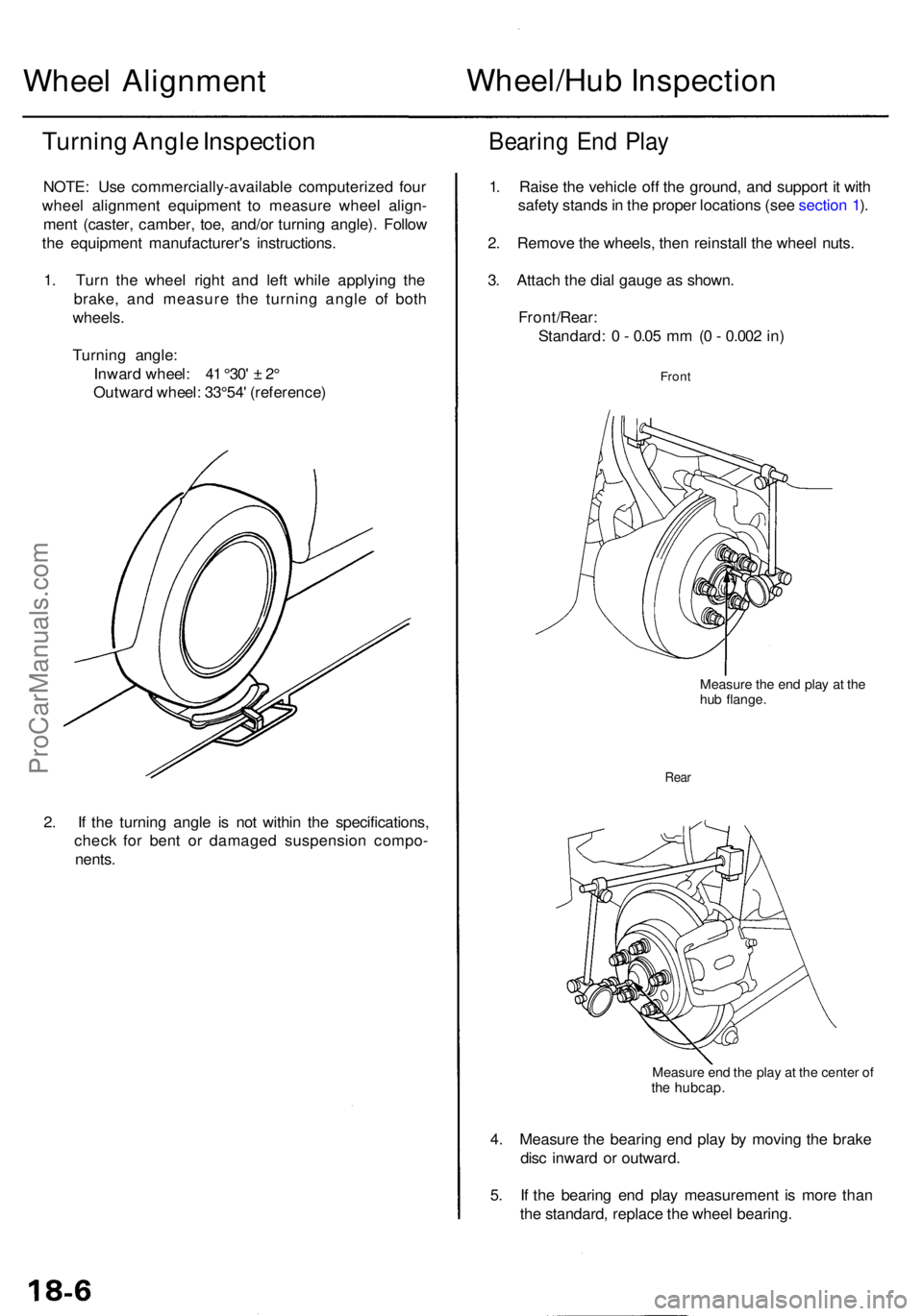
Wheel Alignmen t Wheel/Hu
b Inspectio n
Turning Angl e Inspectio n
NOTE: Us e commercially-availabl e computerize d fou r
whee l alignmen t equipmen t t o measur e whee l align -
men t (caster , camber , toe , and/o r turnin g angle) . Follo w
th e equipmen t manufacturer' s instructions .
1 . Tur n th e whee l righ t an d lef t whil e applyin g th e
brake , an d measur e th e turnin g angl e o f bot h
wheels .
Turnin g angle :
Inwar d wheel :
41 °30 ' ± 2°
Outwar d wheel :
33°54' (reference )
Bearing En d Pla y
2. I f th e turnin g angl e i s no t withi n th e specifications ,
chec k fo r ben t o r damage d suspensio n compo -
nents . 1
. Rais e th e vehicl e of f th e ground , an d suppor t i t wit h
safet y stand s in th e prope r location s (se e sectio n 1 ).
2 . Remov e th e wheels , the n reinstal l th e whee l nuts .
3 . Attac h th e dia l gaug e a s shown .
Front/Rear :
Standard : 0 - 0.0 5 m m (0 - 0.00 2 in )
Fron t
Measur e th e en d pla y a t th ehu b flange .
Rear
Measur e en d th e pla y a t th e cente r o fth e hubcap .
4. Measur e th e bearin g en d pla y b y movin g th e brak e
dis c inwar d o r outward .
5 . If th e bearin g en d pla y measuremen t i s mor e tha n
th e standard , replac e th e whee l bearing .
ProCarManuals.com
Page 1030 of 1954
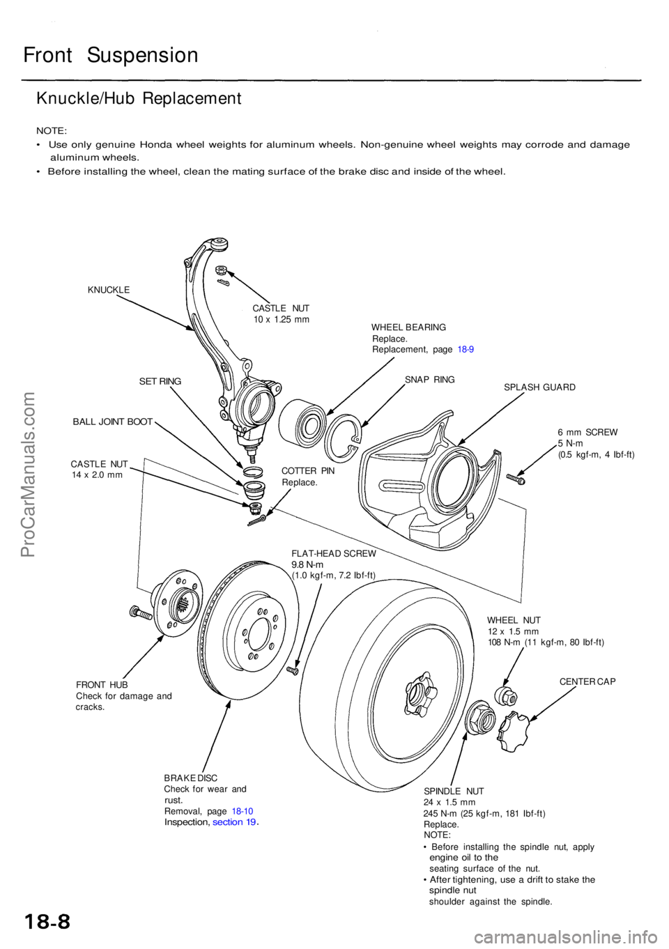
Front Suspensio n
Knuckle/Hub Replacemen t
NOTE:
• Us e onl y genuin e Hond a whee l weight s fo r aluminu m wheels . Non-genuin e whee l weight s ma y corrod e an d damag e
aluminu m wheels .
• Befor e installin g th e wheel , clea n th e matin g surfac e o f th e brak e dis c an d insid e o f th e wheel .
KNUCKL E
WHEEL BEARIN G
Replace .
Replacement , pag e 18- 9
SPLASH GUAR D
BALL JOIN T BOO T
CASTL E NU T14 x 2. 0 m m
FRON T HU B
Chec k fo r damag e an d
cracks .
BRAKE DIS C
Chec k fo r wea r an d
rust .Removal , pag e 18-1 0Inspection , sectio n 1 9
6 m m SCRE W5 N- m(0.5 kgf-m , 4 Ibf-ft )
WHEE L NU T
12 x 1. 5 m m108 N- m (1 1 kgf-m , 8 0 Ibf-ft )
CENTE R CA P
SPINDL E NU T
24 x 1. 5 m m245 N- m (2 5 kgf-m , 18 1 Ibf-ft )
Replace .
NOTE :
• Befor e installin g th e spindl e nut , appl y
engine oi l t o th eseatin g surfac e o f th e nut .• Afte r tightening , us e a drif t t o stak e th espindl e nu tshoulde r agains t th e spindle .
FLAT-HEA
D SCRE W
9.8 N- m(1.0 kgf-m , 7. 2 Ibf-ft )
COTTE
R PI N
Replace .
SNAP RIN G
CASTL
E NU T
10 x 1.2 5 mm
SE T RIN G
ProCarManuals.com
Page 1039 of 1954

Front Damper
Removal
1. Remove the brake hose clamps from the damper.
BRAKE HOSE
CLAMPS
FLANGE
BOLT
FLANGE BOLT
DAMPER FORK
SELF-LOCKING NUT
12 x
1.25
mm
Replace.
2. Remove the flange bolt.
3. Remove the flange bolt and self-locking nut, then
remove the damper fork.
4. Remove the damper by removing the five flange
nuts.
NOTE: Mark the right and left dampers or store them
separately. Do not confuse them on installation.
FLANGE NUTS
Disassembly/Inspection
Disassembly
1. Compress the damper spring with the spring com-
pressor according to the manufacturer's instructions,
then remove the self-locking nut.
CAUTION: Do not compress the spring more than
necessary to remove the nut.
SELF-LOCKING NUT
10 x
1.25
mm
Replace.
STRUT SPRING
COMPRESSOR:
(Commercially available)
BRANICK® T/N MST-580A, T/N 7200,
or equivalent
2. Remove the damper from the spring compressor,
then disassemble the damper as shown on the next
page.
Inspection
1. Reassemble all parts, except the spring.
2. Push on the damper as shown.
WOODEN
BLOCK
3. Check for smooth operation through a full stroke,
both compression and extension.
NOTE: The damper should move smoothly. If it does
not (no compression or no extension), the gas is
leaking and the damper should be replaced.
4. Check for oil leaks, abnormal noises, or binding dur-
ing these tests.ProCarManuals.com
Page 1041 of 1954
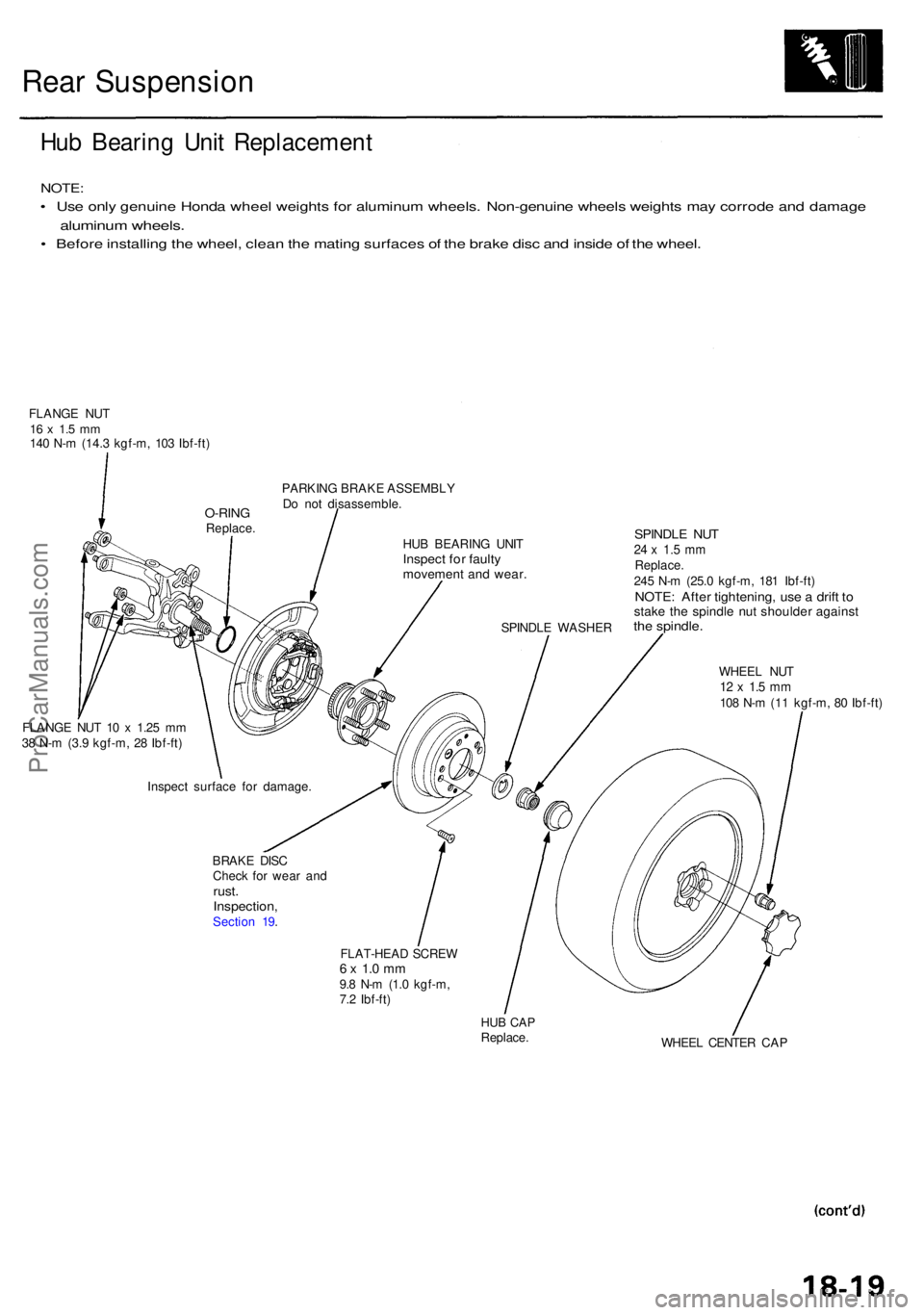
Rear Suspensio n
Hub Bearin g Uni t Replacemen t
NOTE:
• Us e onl y genuin e Hond a whee l weight s fo r aluminu m wheels . Non-genuin e wheel s weight s ma y corrod e an d damag e
aluminum wheels .
• Befor e installin g th e wheel , clea n th e matin g surface s o f th e brak e dis c an d insid e o f th e wheel .
FLANG E NU T16 x 1. 5 m m140 N- m (14. 3 kgf-m , 10 3 Ibf-ft )
PARKING BRAK E ASSEMBL Y
D o no t disassemble .
HU B BEARIN G UNI T
Inspec t fo r fault ymovemen t an d wear .
SPINDL E WASHE R
SPINDLE NU T24 x 1. 5 m mReplace .245 N- m (25. 0 kgf-m , 18 1 Ibf-ft )NOTE : Afte r tightening , us e a drif t t ostak e th e spindl e nu t shoulde r agains tthe spindle .
WHEEL NU T12 x 1. 5 m m108 N- m (1 1 kgf-m , 8 0 Ibf-ft )
FLANG E NU T 1 0 x 1.2 5 m m
3 8 N- m (3. 9 kgf-m , 2 8 Ibf-ft )
BRAKE DIS C
Chec k fo r wea r an d
rust .Inspection ,Section 19 .
FLAT-HEAD SCRE W
6 x 1. 0 m m9.8 N- m (1. 0 kgf-m ,
7. 2 Ibf-ft )
HUB CA PReplace .
WHEEL CENTE R CA P
Inspec
t surfac e fo r damage .
O-RINGReplace .
ProCarManuals.com
Page 1049 of 1954
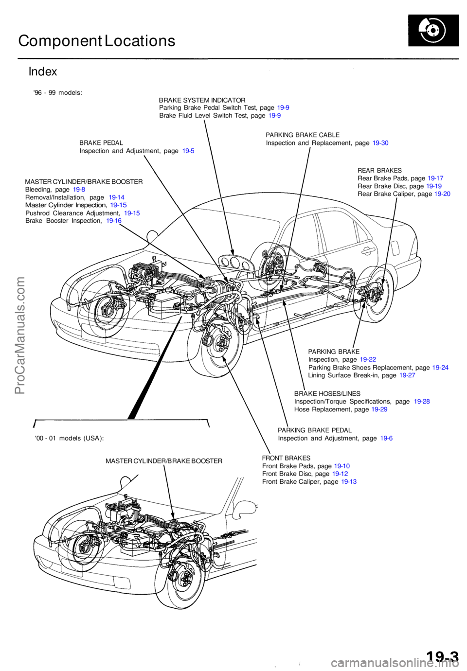
Component Location s
Index
'96 - 9 9 models :
BRAKE SYSTE M INDICATO R
Parkin g Brak e Peda l Switc h Test , pag e 19- 9
Brak e Flui d Leve l Switc h Test , pag e 19- 9
BRAK E PEDA LInspectio n an d Adjustment , pag e 19- 5
PARKIN G BRAK E CABL EInspectio n an d Replacement , pag e 19-3 0
MASTE R CYLINDER/BRAK E BOOSTE R
Bleeding , pag e 19- 8
Removal/Installation , pag e 19-1 4
Maste r Cylinde r Inspection , 19-1 5Pushro d Clearanc e Adjustment , 19-1 5
Brak e Booste r Inspection , 19-1 6
REA R BRAKE SRear Brak e Pads , pag e 19-1 7
Rea r Brak e Disc , pag e 19-1 9
Rea r Brak e Caliper , pag e 19-2 0
PARKIN G BRAK EInspection , pag e 19-2 2
Parkin g Brak e Shoe s Replacement , pag e 19-2 4
Linin g Surfac e Break-in , pag e 19-2 7
BRAK E HOSES/LINE S
Inspection/Torqu e Specifications , pag e 19-2 8
Hos e Replacement , pag e 19-2 9
PARKIN G BRAK E PEDA LInspectio n an d Adjustment , pag e 19- 6
FRON T BRAKE SFront Brak e Pads , pag e 19-1 0
Fron t Brak e Disc , pag e 19-1 2
Fron t Brak e Caliper , pag e 19-1 3
MASTE
R CYLINDER/BRAK E BOOSTE R
'0
0 - 0 1 model s (USA) :
ProCarManuals.com