brake ACURA RL KA9 1996 Service Workshop Manual
[x] Cancel search | Manufacturer: ACURA, Model Year: 1996, Model line: RL KA9, Model: ACURA RL KA9 1996Pages: 1954, PDF Size: 61.44 MB
Page 1073 of 1954
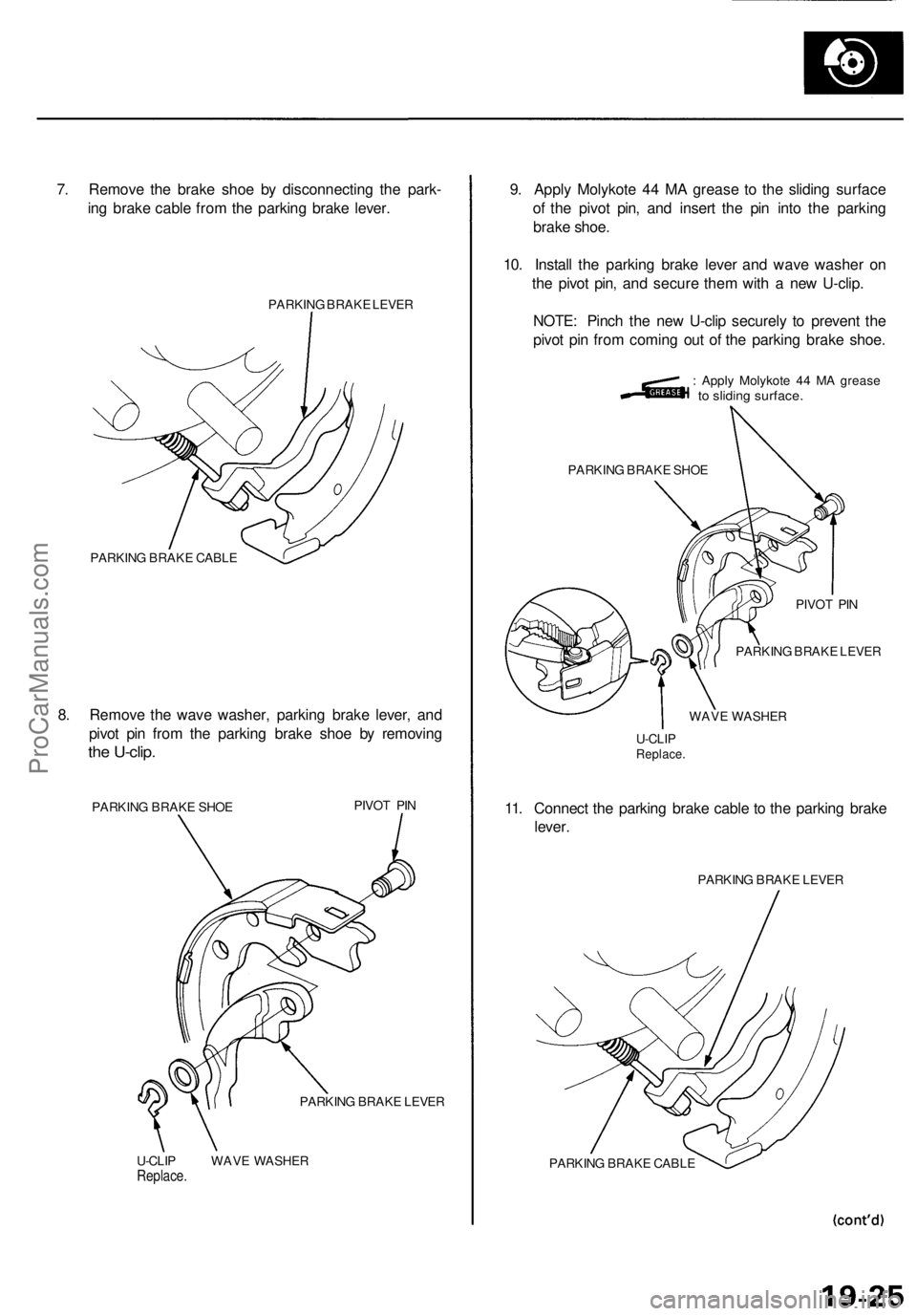
7. Remove the brake shoe by disconnecting the park-
ing brake cable from the parking brake lever.
PARKING BRAKE LEVER
PARKING BRAKE CABLE
8. Remove the wave washer, parking brake lever, and
pivot pin from the parking brake shoe by removing
the U-clip.
PARKING BRAKE SHOE
PIVOT PIN
PARKING BRAKE LEVER
U-CLIP WAVE WASHER
Replace.
9. Apply Molykote 44 MA grease to the sliding surface
of the pivot pin, and insert the pin into the parking
brake shoe.
10. Install the parking brake lever and wave washer on
the pivot pin, and secure them with a new U-clip.
NOTE: Pinch the new U-clip securely to prevent the
pivot pin from coming out of the parking brake shoe.
: Apply Molykote 44 MA grease
to sliding surface.
PARKING BRAKE SHOE
PIVOT PIN
PARKING BRAKE LEVER
WAVE WASHER
U-CLIP
Replace.
11. Connect the parking brake cable to the parking brake
lever.
PARKING BRAKE LEVER
PARKING BRAKE CABLEProCarManuals.com
Page 1074 of 1954
Parking Brake
Parking Brake Shoes Replacement (cont'd)
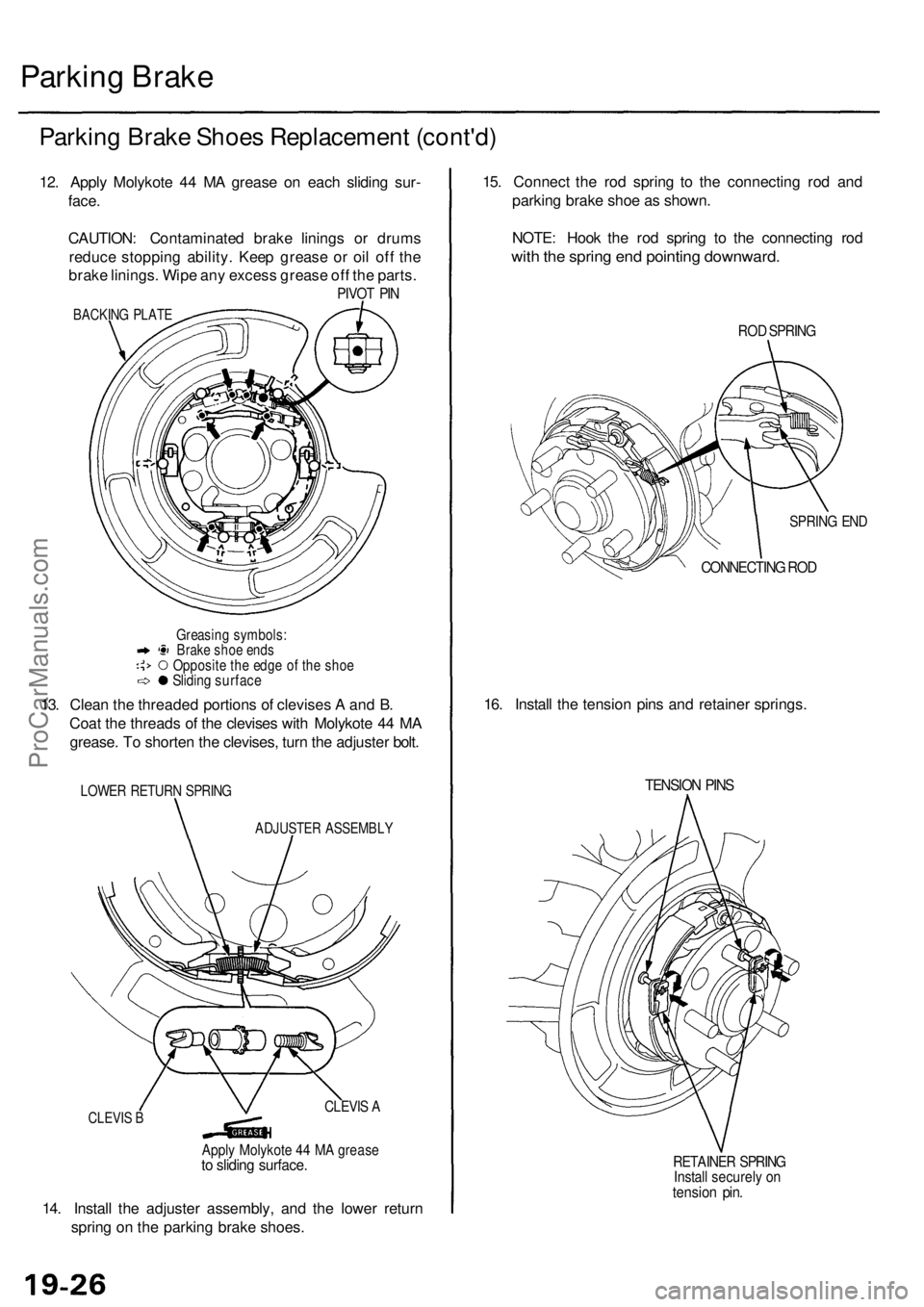
12. Apply Molykote 44 MA grease on each sliding sur-
face.
CAUTION: Contaminated brake linings or drums
reduce stopping ability. Keep grease or oil off the
brake linings. Wipe any excess grease off the parts.
PIVOT PIN
BACKING PLATE
Greasing symbols:
Brake shoe ends
Opposite the edge of the shoe
Sliding surface
13. Clean the threaded portions of clevises A and B.
Coat the threads of the clevises with Molykote 44 MA
grease. To shorten the clevises, turn the adjuster bolt.
LOWER RETURN SPRING
ADJUSTER ASSEMBLY
14. Install the adjuster assembly, and the lower return
spring on the parking brake shoes.
15. Connect the rod spring to the connecting rod and
parking brake shoe as shown.
NOTE: Hook the rod spring to the connecting rod
with the spring end pointing downward.
ROD SPRING
SPRING END
CONNECTING ROD
16. Install the tension pins and retainer springs.
TENSION PINS
RETAINER SPRING
Install securely on
tension pin.
CLEVIS B
CLEVIS A
Apply Molykote 44 MA grease
to sliding surface.ProCarManuals.com
Page 1077 of 1954
Brake Hoses/Lines
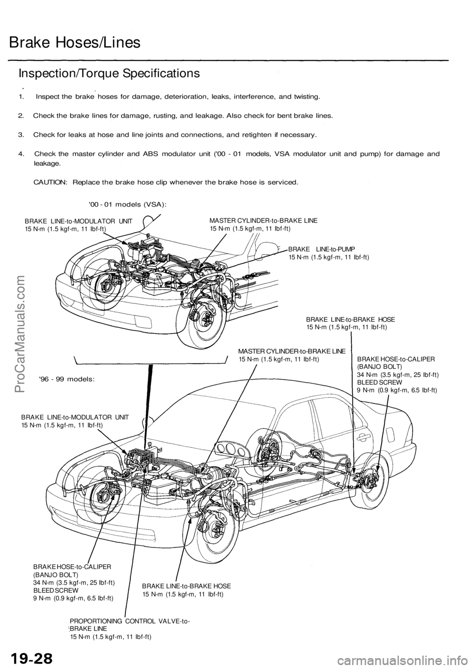
Inspection/Torque Specifications
1. Inspect the brake hoses for damage, deterioration, leaks, interference, and twisting.
2. Check the brake lines for damage, rusting, and leakage. Also check for bent brake lines.
3. Check for leaks at hose and line joints and connections, and retighten if necessary.
4. Check the master cylinder and ABS modulator unit ('00 - 01 models, VSA modulator unit and pump) for damage and
leakage.
CAUTION: Replace the brake hose clip whenever the brake hose is serviced.
'00 - 01 models (VSA):
BRAKE LINE-to-MODULATOR UNIT
15 N-m (1.5 kgf-m, 11 Ibf-ft)
MASTER CYLINDER-to-BRAKE LINE
15 N-m (1.5 kgf-m, 11 Ibf-ft)
BRAKE LINE-to-PUMP
15 N-m (1.5 kgf-m, 11 Ibf-ft)
BRAKE LINE-to-BRAKE HOSE
15 N-m (1.5 kgf-m, 11 Ibf-ft)
MASTER CYLINDER-to-BRAKE LINE
15 N-m (1.5 kgf-m, 11 Ibf-ft)
'96 - 99 models:
BRAKE LINE-to-MODULATOR UNIT
15 N-m (1.5 kgf-m, 11 Ibf-ft)
BRAKE HOSE-to-CALIPER
(BANJO BOLT)
34 N-m (3.5 kgf-m, 25 Ibf-ft)
BLEED SCREW
9 N-m (0.9 kgf-m, 6.5 Ibf-ft)
BRAKE HOSE-to-CALIPER
(BANJO BOLT)
34 N-m (3.5 kgf-m, 25 Ibf-ft)
BLEED SCREW
9 N-m (0.9 kgf-m, 6.5 Ibf-ft)
BRAKE LINE-to-BRAKE HOSE
15 N-m (1.5 kgf-m, 11 Ibf-ft)
PROPORTIONING CONTROL VALVE-to-
BRAKE LINE
15 N-m (1.5 kgf-m, 11 Ibf-ft)ProCarManuals.com
Page 1078 of 1954
Hose Replacemen t
CAUTION:
Befor e reassembling , chec k tha t al l part s ar e fre e o f
dus t an d othe r foreig n particles .
Replace part s wit h ne w one s wheneve r specifie d t o
do so .
Do no t spil l brak e flui d o n th e vehicle ; i t ma y damag e
th e paint ; i f brak e flui d doe s contac t th e paint , was h
it of f immediatel y wit h water .
1. Replac e th e brak e hos e if th e hos e is twisted , cracked ,
o r i f i t leaks .
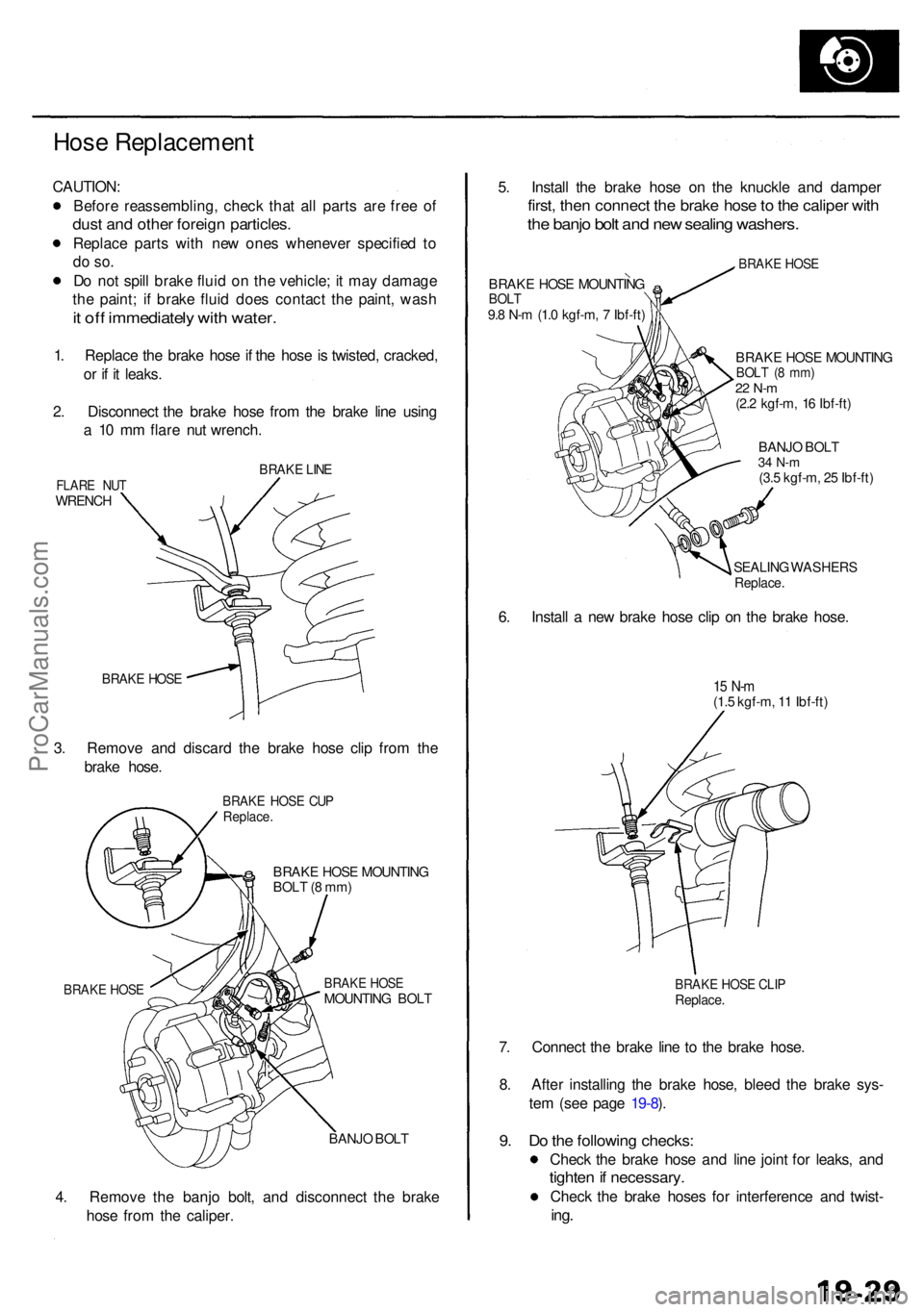
2 . Disconnec t th e brak e hos e fro m th e brak e lin e usin g
a 1 0 m m flar e nu t wrench .
BRAKE LIN EFLAR E NU TWRENC H
BRAKE HOS E
3. Remov e an d discar d th e brak e hos e cli p fro m th e
brak e hose .
BRAK E HOS E CU PReplace .
BRAKE HOS E MOUNTIN G
BOL T (8 mm )
BRAK E HOS EMOUNTIN G BOL TBRAK E HOS E
BANJ O BOL T
4. Remov e th e banj o bolt , an d disconnec t th e brak e
hos e fro m th e caliper . 5
. Instal l th e brak e hos e o n th e knuckl e an d dampe r
first, the n connec t th e brak e hos e to th e calipe r wit h
the banj o bol t an d ne w sealin g washers .
BRAKE HOS E MOUNTIN GBOLT9.8 N- m (1. 0 kgf-m , 7 Ibf-ft )
BRAK E HOS E
BRAK E HOS E MOUNTIN GBOLT ( 8 mm )22 N- m(2.2 kgf-m , 1 6 Ibf-ft )
BANJ O BOL T
34 N- m(3.5 kgf-m , 2 5 Ibf-ft )
SEALIN G WASHER S
Replace.
6. Instal l a ne w brak e hos e cli p o n th e brak e hose .
15 N- m(1.5 kgf-m , 1 1 Ibf-ft )
BRAK E HOS E CLI PReplace .
7. Connec t th e brak e lin e t o th e brak e hose .
8 . Afte r installin g th e brak e hose , blee d th e brak e sys -
te m (se e pag e 19-8 ).
9 . D o th e followin g checks :
Check th e brak e hos e an d lin e join t fo r leaks , an d
tighte n if necessary .
Check th e brak e hose s fo r interferenc e an d twist -
ing.
ProCarManuals.com
Page 1084 of 1954
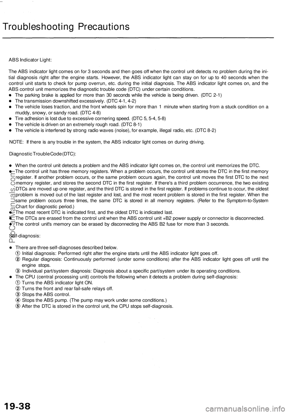
Troubleshooting Precautions
ABS Indicator Light:
The ABS indicator light comes on for 3 seconds and then goes off when the control unit detects no problem during the ini-
tial diagnosis right after the engine starts. However, the ABS indicator light can stay on for up to 40 seconds when the
control unit starts to check for pump overrun, etc. during the initial diagnosis. The ABS indicator light comes on, and the
ABS control unit memorizes the diagnostic trouble code (DTC) under certain conditions.
The parking brake is applied for more than 30 seconds while the vehicle is being driven. (DTC 2-1)
The transmission downshifted excessively. (DTC 4-1, 4-2)
The vehicle loses traction, and the front wheels spin for more than 1 minute when starting from a stuck condition on a
muddy, snowy, or sandy road. (DTC 4-8)
Tire adhesion is lost due to excessive cornering speed. (DTC 5, 5-4, 5-8)
The vehicle is driven on an extremely rough road. (DTC 8-1)
The vehicle is interfered by strong radio waves (noise), for example, illegal radio, etc. (DTC 8-2)
NOTE: If there is any trouble in the system, the ABS indicator light comes on during driving.
Diagnostic Trouble Code (DTC):
When the control unit detects a problem and the ABS indicator light comes on, the control unit memorizes the DTC.
The control unit has three memory registers. When a problem occurs, the control unit stores the DTC in the first memory
register. If another problem occurs, or the same problem occurs again, the control unit moves the first DTC to the next
memory register, and stores the second DTC in the first register. If there's a third problem occurrence, the two existing
DTCs are moved up one register, and the third DTC is stored in the first register. If problems continue to occur, the oldest
problem is moved out of the last register and lost, and the most recent problem is stored in the first register. When the
same problem occurs three times, the same DTC is stored in all memory registers. (Refer to the Symptom-to-System
Chart for diagnostic period.)
The most recent DTC is indicated first, and the oldest DTC is indicated last.
The DTCs are erased from the control unit when the ABS control unit +B2 power supply or connector is disconnected.
The control unit's memory can be erased by disconnecting the ABS B2 fuse for more than 3 seconds.
Self-diagnosis:
There are three self-diagnoses described below.
Initial diagnosis: Performed right after the engine starts until the ABS indicator light goes off.
Regular diagnosis: Continuously performed (under some conditions) after the ABS indicator light goes off until the
engine stops.
Individual part/system diagnosis: Diagnosis about a specific part/system under its operating conditions.
The CPU (central processing unit) controls the following when it detects a problem during self-diagnosis:
Turns the ABS indicator light ON.
Turns the front and rear fail-safe relays off.
Stops the ABS control.
Stops the ABS pump. (The pump may work under some conditions.)
After the DTC is stored in the control unit, the CPU stops self-diagnosis.ProCarManuals.com
Page 1114 of 1954

Troubleshooting
DTC 5 , 5-4 , 5-8 : Rea r Whee l Loc k
The AB S contro l uni t monitor s th e rea r whee l senso r signal s durin g th e regula r diagnosi s (durin g driving) . Thi s diagnosi s
is no t performe d whe n th e parkin g brak e signa l i s ON . Th e AB S contro l uni t turn s th e AB S indicato r ligh t o n if i t detect s n o
signal(s ) fro m th e rea r whee l sensor(s ) du e to , fo r example , rea r whee l lock .
Possibl e causes :
Wheel spi n durin g cornerin g
Open circuit , interna l shor t o r shor t t o th e bod y groun d in th e whee l senso r syste m
Rear brak e dra g
Modulato r doe s no t decreas e pressur e properl y
Faulty AB S contro l uni t
— Whe n vehicl e i s driven , ABSindicato r ligh t i s ON .— Wit h th e SC S servic e connec -tor connecte d (se e pag e 19-40 ),DTC s 5 , 5- 4 and/o r 5- 8 ar e indi -
cated .
Chec k th e PAR K circuit :
1. Tur n th e ignitio n switc h O N (II) .2. Pres s th e parking brake pedal .
Doe s th e brak e syste m ligh t
com e on ? Parkin
g brak e switc h stuc k OFF .
Repai r ope n circui t betwee n th e
under-das h fuse/rela y bo x an d
parkin g brak e switch .
NOTE:The self-diagnosi s o f th e whee l senso r i s per -forme d i n thi s step .
Test-driv e wit h th e parkin g brak e released .
Does th e AB S indicato r ligh tcom e on ?
Chec k fo r rea r brak e drag :
1 . Rais e th e rea r o f th e vehicle ,
and suppor t i t wit h safet ystands (se e sectio n 1 ).2 . Spi n th e lef t and/o r righ t rea rwhee l an d chec k fo r brak e
drag . I
s cod e 4- 4 o r 4- 8 indicated ?
Perform th e troubleshootin g fo rthe rea r whee l sensor .
Perfor m th e appropriat e trouble -
shootin g fo r th e code .
Doe s th e brak e drag ?
Repair th e rea r brak e drag .
Check th e AB S functio n (se epage 19-95 ).
Th e probabl e caus e wa s tha t
tractio n wa s los t du e t o exces -
siv e cornerin g speed , etc .
Chec
k th e self-diagnosis :
Test-driv e th e vehicl e a t speed s
of 6 mp h (1 0 km/h ) o r more .
Confir m th e DT C (se e pag e 19-40 ).
ProCarManuals.com
Page 1141 of 1954
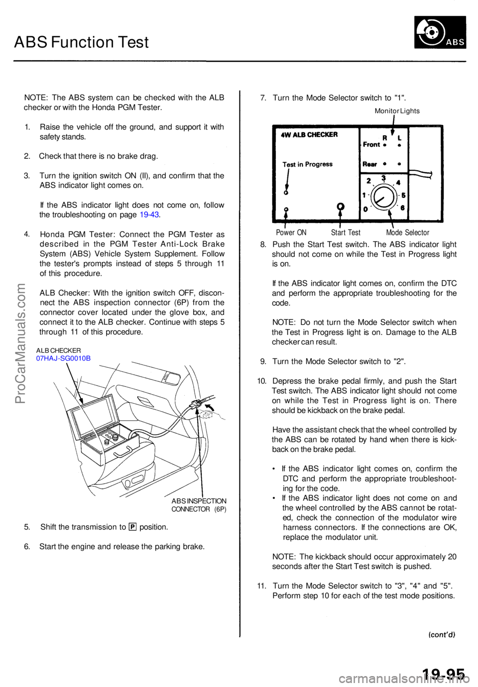
ABS Functio n Tes t
NOTE : Th e AB S syste m ca n b e checke d wit h th e AL B
checke r o r wit h th e Hond a PG M Tester .
1 . Rais e th e vehicl e of f th e ground , an d suppor t i t wit h
safet y stands .
2 . Chec k tha t ther e is n o brak e drag .
3 . Tur n th e ignitio n switc h O N (II) , an d confir m tha t th e
AB S indicato r ligh t come s on .
I f th e AB S indicato r ligh t doe s no t com e on , follo w
th e troubleshootin g o n pag e 19-43 .
4.Hond a PG M Tester : Connec t th e PG M Teste r a s
describe d i n th e PG M Teste r Anti-Loc k Brak e
Syste m (ABS ) Vehicl e Syste m Supplement . Follo w
th e tester' s prompt s instea d o f step s 5 throug h 1 1
o f thi s procedure .
AL B Checker : Wit h th e ignitio n switc h OFF , discon -
nec t th e AB S inspectio n connecto r (6P ) fro m th e
connecto r cove r locate d unde r th e glov e box , an d
connec t i t t o th e AL B checker . Continu e wit h step s 5
throug h 1 1 o f thi s procedure .
ALB CHECKE R07HAJ-SG0010 B
ABS INSPECTIO N
CONNECTO R (6P )
5. Shif t th e transmissio n t o position .
6 . Star t th e engin e an d releas e th e parkin g brake . 7
. Tur n th e Mod e Selecto r switc h t o "1" .
Monito r Light s
Powe r O N Star t Tes t Mod e Selecto r
8. Pus h th e Star t Tes t switch . Th e AB S indicato r ligh t
shoul d no t com e o n whil e th e Tes t i n Progres s ligh t
is on .
If th e AB S indicato r ligh t come s on , confir m th e DT C
an d perfor m th e appropriat e troubleshootin g fo r th e
code .
NOTE : D o no t tur n th e Mod e Selecto r switc h whe n
th e Tes t i n Progres s ligh t i s on . Damag e t o th e AL B
checke r ca n result .
9 . Tur n th e Mod e Selecto r switc h t o "2" .
10 . Depres s th e brak e peda l firmly , an d pus h th e Star t
Tes t switch . Th e AB S indicato r ligh t shoul d no t com e
o n whil e th e Tes t i n Progres s ligh t i s on . Ther e
shoul d b e kickbac k o n th e brak e pedal .
Hav e th e assistan t chec k tha t th e whee l controlle d b y
th e AB S ca n b e rotate d b y han d whe n ther e is kick -
bac k o n th e brak e pedal .
• I f th e AB S indicato r ligh t come s on , confir m th e
DT C an d perfor m th e appropriat e troubleshoot -
in g fo r th e code .
• I f th e AB S indicato r ligh t doe s no t com e o n an d
th e whee l controlle d b y th e AB S canno t b e rotat -
ed , chec k th e connectio n o f th e modulato r wir e
harnes s connectors . I f th e connection s ar e OK ,
replac e th e modulator unit.
NOTE : Th e kickbac k shoul d occu r approximatel y 2 0
second s afte r th e Star t Tes t switc h is pushed .
11 . Tur n th e Mod e Selecto r switc h t o "3" , "4 " an d "5" .
Perfor m ste p 1 0 fo r eac h o f th e tes t mod e positions .
ProCarManuals.com
Page 1144 of 1954
Modulator Uni t
High-Pressur e Brak e Flui d Replacement/Bleedin g
Replacement
1. Reliev e syste m pressur e (se e pag e 19-97 ). Leav e th e
tub e an d wrenc h o n th e maintenanc e bleeder , an d
leav e th e tub e in th e container .
2 . Star t th e engin e t o operat e th e pum p motor .
NOTE:
If th e pum p moto r operate s fo r 4 0 second s o r
more , th e AB S indicato r ligh t come s on , an d th e
pum p moto r stops . Sto p an d restar t th e engin e t o
operat e th e pum p moto r again .
I f th e AB S indicator light come s on , remov e th e
AB S B 2 (1 5 A ) fus e fo r 3 second s o r mor e t o
eras e th e DT C afte r servicing .
3 . Repea t step s 1 an d 2 to drai n th e res t o f th e brak e
fluid fro m th e modulato r unit .
NOTE : Th e modulato r ha s a capacit y o f approxi -
mately 15 0 (5. 0 fl-oz , 5. 3 Imp-oz) . Approximatel y
35 - 4 5 (1. 2 - 1. 5 fl-oz , 1. 2 - 1. 6 Imp-oz ) o f th e flui d
i s draine d eac h tim e yo u reliev e syste m pressure .
4 . Remov e th e cap , an d refil l th e reservoi r t o th e MA X
(upper ) leve l wit h fres h brak e fluid .
NOTE : Pou r th e brak e flui d slowl y s o tha t i t doe s
not foam , an d wai t fo r a fe w minutes .
5. Repea t step s 1 an d 2 twice , an d refil l th e reservoi r
t o th e MA X (upper ) leve l wit h fres h brak e fluid .
6 . Tighte n th e maintenanc e bleede r t o th e specifie d
torque .
7 . Star t th e engine , an d mak e sur e tha t th e AB S indica -
tor ligh t goe s off .
Bleedin g
Whe n th e brak e flui d i s completel y draine d fro m th e
reservoi r (ai r enter s th e modulato r unit) , blee d th e ai r
from th e modulato r a s follows :
1 . Fil l th e reservoi r t o th e MA X (upper ) leve l wit h fres h
brake fluid .
2. Connec t a tub e t o th e maintenanc e bleede r o n th e
modulato r unit , an d se t th e othe r en d o f th e tub e in a
suitabl e containe r (se e pag e 19-97 ).
3 . Loose n th e bleeder , an d star t th e engin e t o operat e
th e pum p motor .
4 . Tighte n th e bleede r whe n th e flui d start s t o flo w ou t
o f th e bleeder .
NOTE : Tak e car e no t t o spil l th e brak e flui d fro m
th e container .
5 . Sto p th e engin e afte r th e pum p moto r stops .
NOTE : I f th e AB S indicato r ligh t come s o n an d th e
pum p moto r stops , restar t th e engin e an d repea t step s
3 throug h 5 above .
19-98ProCarManuals.com
Page 1153 of 1954

Anti-lock Brake System (ABS)
Features/Construction (cont'd)
ABS Control
The ABS control unit detects the wheel speed based on the wheel sensor signal it received, then it calculates the vehicle
speed based on the detected wheel speed. The control unit detects the vehicle speed during deceleration based on the
rate of deceleration.
The ABS control unit calculates the slip rate of each wheel, and it transmits the control signal to the modulator unit
solenoid valve when the slip rate is high.
The pressure reduction control has 3-modes: pressure reduction, pressure retaining, and pressure intensifying.
ABS CONTROL UNITProCarManuals.com
Page 1157 of 1954
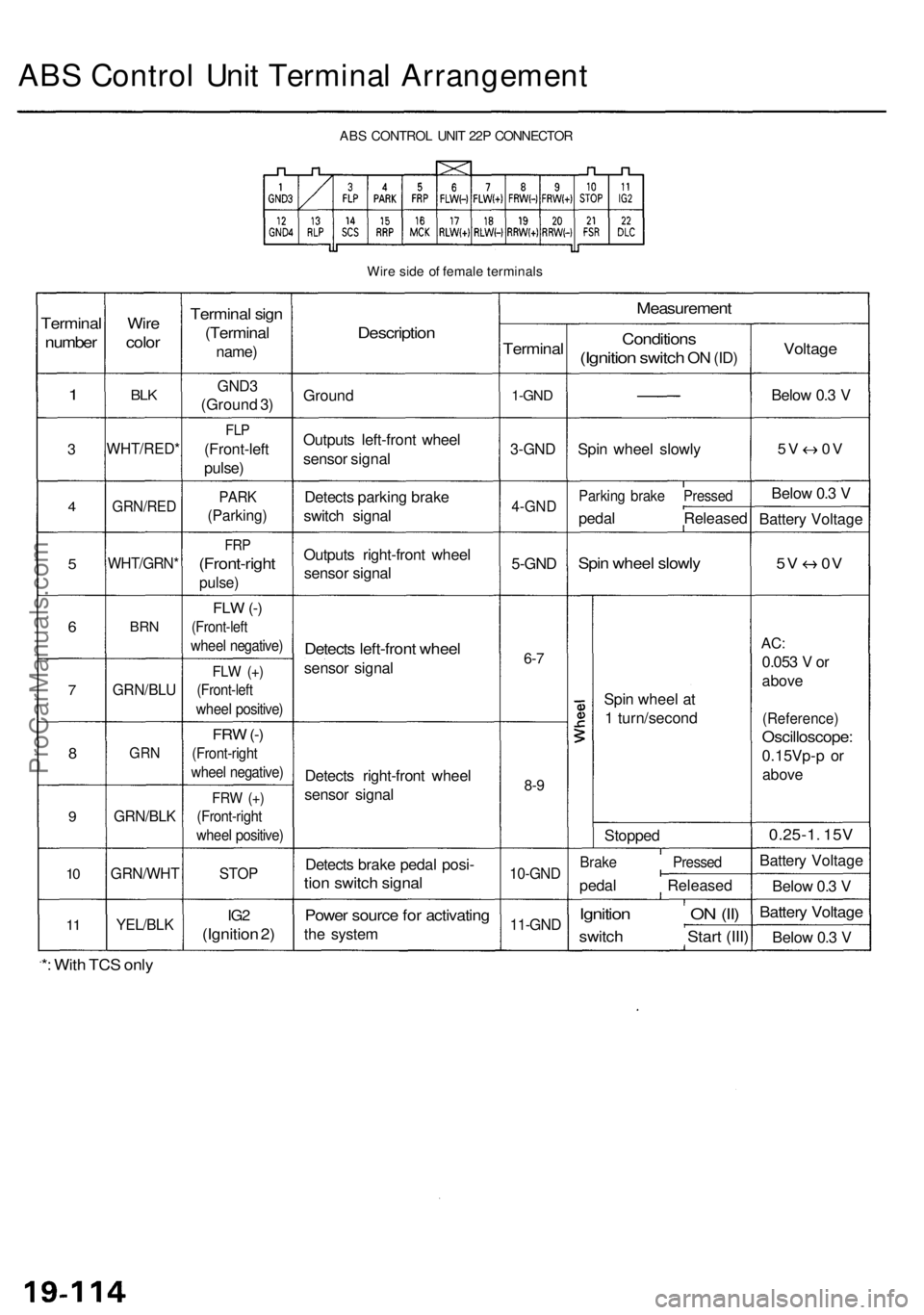
ABS Contro l Uni t Termina l Arrangemen t
ABS CONTRO L UNI T 22 P CONNECTO R
Wir e sid e o f femal e terminal s
Terminal
number
1
3
4
5
6
7
8
9
10
1 1
Wir e
colo r
BLK
WHT/RED *
GRN/RED
WHT/GRN *
BRN
GRN/BL U
GRN
GRN/BL K
GRN/WH T
YEL/BLK
Termina l sig n
(Termina l
name)
GND3
(Groun d 3 )
FL P
(Front-lef t
pulse )
PARK
(Parking )
FRP
(Front-righ t
pulse)
FLW (-)
(Front-lef t
wheel negative )
FLW (+ )
(Front-lef t
wheel positive )
FRW (-)
(Front-righ t
wheel negative )
FRW (+ )
(Front-righ t
wheel positive )
STOP
IG2
(Ignitio n 2 )
Descriptio n
Ground
Output s left-fron t whee l
senso r signa l
Detect s parkin g brak e
switc h signa l
Output s right-fron t whee l
senso r signa l
Detect s left-fron t whee l
senso r signa l
Detect s right-fron t whee l
senso r signa l
Detect s brak e peda l posi -
tion switc h signa l
Power sourc e fo r activatin g
the syste m
Measuremen t
Terminal
1-GND
3-GN D
4-GN D
5-GND
6-7
8- 9
10-GN D
11-GND
Condition s
(Ignition switch ON (ID )
Spi n whee l slowl y
Parkin g brak e Presse d
pedal Release d
Spin whee l slowl y
Spin whee l a t
1 turn/secon d
Stoppe d
Brake Presse d
pedal Release d
Ignition O N (II )
switc h Star t (III )
Voltag e
Below 0. 3 V
5 V 0 V
Below 0. 3 V
Batter y Voltag e
5V 0 V
AC:
0.05 3 V or
abov e
(Reference )
Oscilloscope :
0.15Vp-p o r
abov e
0.25-1 . 15 V
Batter y Voltag e
Belo w 0. 3 V
Batter y Voltag e
Below 0. 3 V
*: Wit h TC S onl y
ProCarManuals.com