brake ACURA RL KA9 1996 Service Manual PDF
[x] Cancel search | Manufacturer: ACURA, Model Year: 1996, Model line: RL KA9, Model: ACURA RL KA9 1996Pages: 1954, PDF Size: 61.44 MB
Page 1161 of 1954
Troubleshooting Precautions
Kickback
1. The motor operates when the ABS is functioning, and the fluid in the reservoir is forced out to the master cylinder,
causing kickback at the brake pedal.
Pump Motor
1. The pump motor operates when the ABS is functioning.
2. The ABS control unit checks the pump motor operation during initial diagnosis when the vehicle is started. You may
hear the motor operate at this time, but it is normal.
Brake Fluid Replacement/Air Bleeding
1. Brake fluid replacement and air bleeding procedures are the same as vehicles without ABS. To ease bleeding, start
with the front wheels.
Troubleshooting
1. The troubleshooting flowcharts procedures assume that the cause of the problem is still present and the ABS indicator
is still on. Following the flowchart when the ABS indicator does not come on can result in incorrect diagnosis.
2. Question the customer about the conditions when the problem occurred, and try to reproduce the same conditions
for troubleshooting.
Find out when the ABS indicator came on, such as during initial diagnosis, during ABS control, after ABS control,
when vehicle speed was at a certain speed, etc.
3. When the ABS indicator does not come on during the test-drive, but troubleshooting is performed based on the DTC,
check for loose connectors, poor contact at the terminals, etc. before you start troubleshooting.
4. After troubleshooting, erase the DTC and test-drive the vehicle. Be sure the ABS indicator does not come on.
5. The connector illustrations show the female terminals with a single outline and the male terminals with a double outline.ProCarManuals.com
Page 1175 of 1954
Troubleshooting
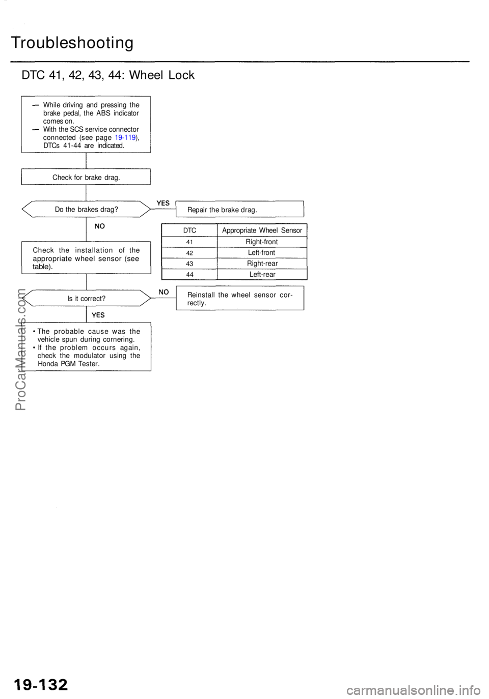
DTC 41 , 42 , 43 , 44 : Whee l Loc k
Do th e brake s drag ?
Repair th e brak e drag .
Chec k th e installatio n o f th e
appropriat e whee l senso r (se etable) .
DTC
41
4 2
43
4 4
Appropriat e Whee l Senso r
Right-fron t
Left-fron t
Right-rea r
Left-rear
I s i t correct ? Reinstal
l th e whee l senso r cor -
rectly .
Th e probabl e caus e wa s th e
vehicl e spu n durin g cornering .
I f th e proble m occur s again ,
chec k th e modulato r usin g th e
Hond a PG M Tester .
Whil
e drivin g an d pressin g th e
brak e pedal , th e AB S indicato r
come s on .
Wit h th e SC S servic e connecto r
connecte d (se e pag e 19-119 ),
DTC s 41-4 4 ar e indicated .
Chec k fo r brak e drag .
ProCarManuals.com
Page 1186 of 1954
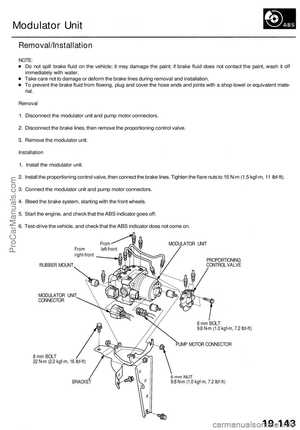
Modulator Unit
Removal/Installation
NOTE:
Do not spill brake fluid on the vehicle; it may damage the paint; if brake fluid does not contact the paint, wash it off
immediately with water.
Take care not to damage or deform the brake lines during removal and installation.
To prevent the brake fluid from flowing, plug and cover the hose ends and joints with a shop towel or equivalent mate-
rial.
Removal
1. Disconnect the modulator unit and pump motor connectors.
2. Disconnect the brake lines, then remove the proportioning control valve.
3. Remove the modulator unit.
Installation
1. Install the modulator unit.
2. Install the proportioning control valve, then connect the brake lines. Tighten the flare nuts to 15 N-m (1.5 kgf-m, 11 Ibf-ft).
3. Connect the modulator unit and pump motor connectors.
4. Bleed the brake system, starting with the front wheels.
5. Start the engine, and check that the ABS indicator goes off.
6. Test-drive the vehicle, and check that the ABS indicator does not come on.
From
From left-front
right-front
MODULATOR UNIT
RUBBER MOUNT
MODULATOR UNIT
CONNECTOR
8 mm BOLT
22 N-m (2.2 kgf-m, 16 Ibf-ft)
BRACKET
PROPORTIONING
CONTROL VALVE
6 mm BOLT
9.8 N-m (1.0 kgf-m, 7.2 Ibf-ft)
PUMP MOTOR CONNECTOR
6 mm NUT
9.8 N-m (1.0 kgf-m, 7.2 Ibf-ft)ProCarManuals.com
Page 1196 of 1954

TCS CONTROL UNIT 20P CONNECTOR
Wire side of female terminals
VB: Battery Voltage
Terminal
number
1
2
4
5
6
9
10
11
12
13
14
15
16
17
20
Wire
color
BLK/YEL
GRN/RED
BLU
PNK/BLU
BLK/WHT
BLK
BRN/WHT
GRN/WHT
BLU
GRN/ORN
BLK/ORN
BRN/BLK
WHT/BLU
BLU/GRY
GRN
BRN
Terminal sign
(Terminal name)
IG1
(Ignition 1)
PARK
(Parking)
SCS
(Service check
signal)
STR-GND
(Steering ground)
AT-SHIFT
(AT shift)
FSR
(Fail-safe relay)
PMG
(Power motor
Ground)
VPM
(Voltage power
motor)
STOP
(Stop)
NEP (Engine
speed pulse)
BARO
(Barometric)
TC-FC
(Traction control
fuel cut)
LG2
(Logic ground 2)
STR-VCC (Steer-
ing power supply)
WARN2
(Warning 2)
SH-MOT
(Shield motor)
MOT +
(Motor +)
MOT-
(Motor -)
Description
Detects ignition switch
IG1 signal
Detects parking brake
switch signal
Detects service check
connector signal
(Diagnostic trouble
code indication)
Ground for the steering
angle sensor
Detects A/T shift posi-
tion signal
Drives fail-safe relay
Power ground for the
TCS control valve
actuator motor
Power source for the
TCS control valve
actuator motor
Detects brake pedal
position switch signal
Detects engine speed
signal
Detects barometric
sensor signal
TCS Fl, Fuel cut
(torque down) signal
Ground for the logic
circuit
Power source for the
steering angle sensor
Drives TCS indicator light
(The indicator light comes
on by the self-bias)
Shield for the TCS con-
trol valve actuator motor
Drives TCS control
valve actuator motor
Drives TCS control
valve actuator motor
Measurement
terminals
1-GND
2
3-GND
4-GND
5-GND
6-GND
9-GND
10-GND
11-GND
12-GND
13-GND
14-GND
15-GND
16-GND
17-GND
19-20
20-19
Voltage
Conditions
(Ignition Switch ON (II))
Depress the parking
brake pedal.
Release the parking
brake pedal.
SCS service connector
connected.
SCS service connector
disconnected.
Shift the transmission
to position, then
start the engine.
Start the engine.
Start the engine.
Brake pedal depressed.
Brake pedal released.
Engine idling
TCS is functioning,
(maximum fuel cut)
TCS is not functioning.
Indicator light ON
Indicator light OFF
TCS is functioning.
TCS is not functioning.
TCS is functioning.
TCS is not functioning.
Output
voltage
VB
Below 0.6 V
VB
0V
5V
Below 0.3V
About 4V
(5V 0V)
VB
1.5V
Below 0.3 V
0V
VB
VB
0V
About 6V
(12V
0V)
About 3 V
About 1.5V
About 4.5 V
(5 V,
PWM)
Below 0.3V
About 5 V
About 2 V
VB
VB
0V
VB
0VProCarManuals.com
Page 1197 of 1954

Troubleshooting Precautions
1. In any of these cases, the TCS indicator light may come on or stay on even the TCS system is normal.
The coolant temperature is 32°F (0°C) or below.
The parking brake is applied for more than 30 seconds while the vehicle is being driven.
The tires are not inflated to the specified pressure.
The wheel sensor signal is interrupted during driving at speeds of 6 mph (10 km/h) or above due to, for example, a
vehicle spinning.
The MAP sensor, the coolant temperature sensor, the ICM or the atmospheric pressure sensor system of the PGM-FI
system is faulty.
2. TCS does not function when the TCS indicator light is ON.
3. When both the TCS indicator light and the MIL are ON, troubleshoot the PGM-FI system first.
4. When both the TCS indicator light and the ABS indicator light are ON, troubleshoot the ABS first.
5. The DTC 4-9 (ABS down) is memorized when the ABS control unit cannot output the wheel speed signal due to, for
example, a missing or blown ABS B2 (15 A) fuse. If you fail to erase the DTC of the TCS after troubleshooting the ABS,
the DTC remains in the TCS control unit memory. Therefore, be sure to test-drive the vehicle, and check the TCS indica-
tor light before starting to troubleshoot the TCS.ProCarManuals.com
Page 1199 of 1954
Diagnostic Trouble Code (DTC)
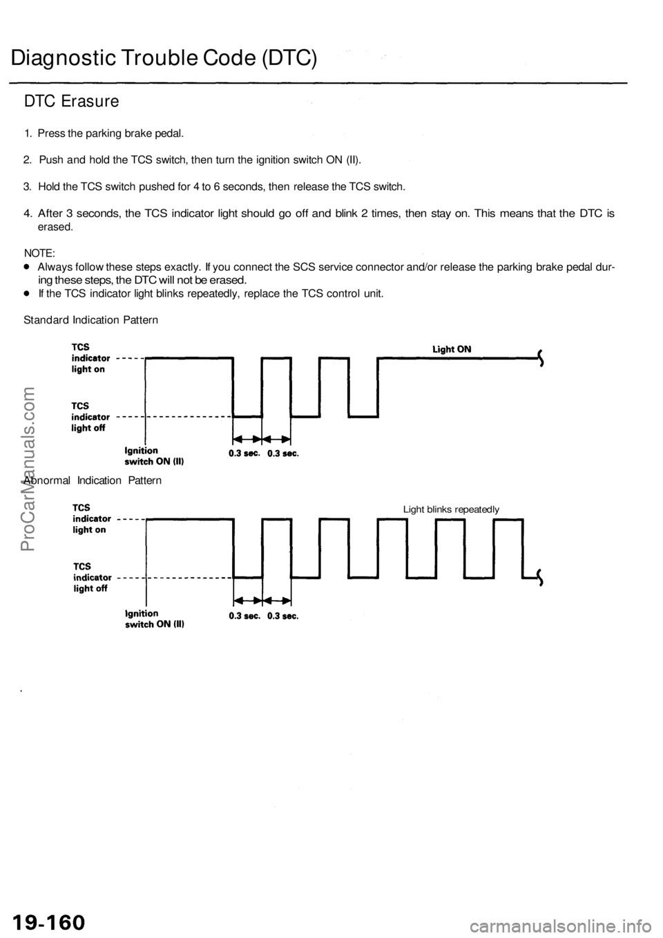
DTC Erasure
1. Press the parking brake pedal.
2. Push and hold the TCS switch, then turn the ignition switch ON (II).
3. Hold the TCS switch pushed for 4 to 6 seconds, then release the TCS switch.
4. After 3 seconds, the TCS indicator light should go off and blink 2 times, then stay on. This means that the DTC is
erased.
NOTE:
Always follow these steps exactly. If you connect the SCS service connector and/or release the parking brake pedal dur-
ing these steps, the DTC will not be erased.
If the TCS indicator light blinks repeatedly, replace the TCS control unit.
Standard Indication Pattern
Abnormal Indication Pattern
Light blinks repeatedlyProCarManuals.com
Page 1234 of 1954

Component Locations
SERVICE CHECK CONNECTOR (2P)
RIGHT-REAR WHEEL SENSOR
VSA CONVERTER UNIT
VSA MODULATOR
CONTROL UNIT
TCS CONTROL
VALVE SENSOR
RIGHT-FRONT
WHEEL SENSOR
PRECHARGE
PUMP MOTOR
STEERING
ANGLE SENSOR
YAW RATE/LATERAL
ACCELERATION SENSOR
TCS CONTROL VALVE
ACTUATOR
UNDER-HOOD
RELAY BOX C
UNDER-HOOD
FUSE/RELAY BOX
VSA OFF SWITCH
UNDER-DASH FUSE/RELAY BOX
LEFT-FRONT WHEEL SENSOR
LEFT-REAR
WHEEL SENSOR
GAUGE ASSEMBLY
ABS INDICATOR
VSA SYSTEM INDICATOR
UNDER-HOOD FUSE/RELAY BOX
STOP/HORN
(20 A) FUSE
BRAKE SYSTEM INDICATOR
VSA ACTIVATION INDICATOR
UNDER-DASH FUSE/RELAY BOX
TCS
(15 A) FUSE
VSA
(20 A) FUSE
METER
(15 A) FUSE
ECU
(20 A) FUSE
METER
(7.5 A) FUSE
BATTERY
(120 A) FUSE
VSA MOTOR (40 A) FUSE
IG SW (50 A) FUSE
UNDER-HOOD RELAY BOX C
FAIL-SAFE RELAY
GAUGE RELAY
PCM
R/C MIRROR
(7.5 A) FUSEProCarManuals.com
Page 1236 of 1954
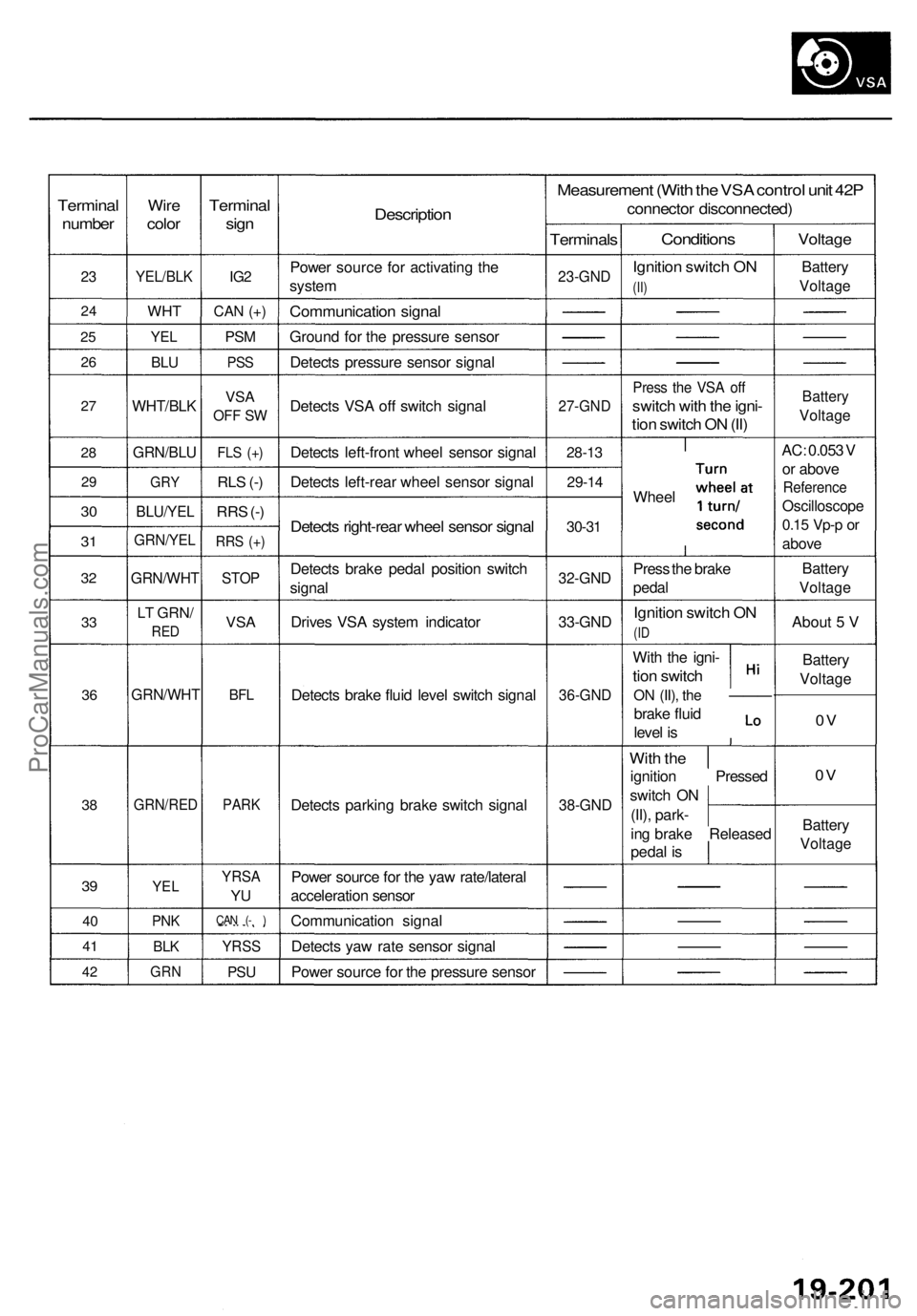
Terminal
number
23
2 4
25
2 6
27
2 8
2 9
30
3 1
3 2
33
3 6
38
39
4 0
4 1
42
Wir e
colo r
YEL/BL K
WHT
YEL
BLU
WHT/BL K
GRN/BLU
GRY
BLU/YE L
GRN/YE L
GRN/WH T
LT GRN /
RED
GRN/WH T
GRN/RED
YEL
PNK
BLK
GR N
Termina l
sign
IG2
CA N (+ )
PS M
PS S
VS A
OF F S W
FL S (+ )
RLS (- )
RR S (- )
RR S (+ )
STO P
VSA
BFL
PAR K
YRS A
YU
CA N ( - )
YRS S
PSU
Descriptio n
Power sourc e fo r activatin g th e
syste m
Communicatio n signa l
Groun d fo r th e pressur e senso r
Detect s pressur e senso r signa l
Detect s VS A of f switc h signa l
Detect s left-fron t whee l senso r signa l
Detect s left-rea r whee l senso r signa l
Detects right-rea r whee l senso r signa l
Detect s brak e peda l positio n switc h
signa l
Drive s VS A syste m indicato r
Detect s brak e flui d leve l switc h signa l
Detect s parkin g brak e switc h signa l
Powe r sourc e fo r th e ya w rate/latera l
acceleratio n senso r
Communicatio n signa l
Detect s ya w rat e senso r signa l
Powe r sourc e fo r th e pressur e senso r
Measuremen t (Wit h th e VS A contro l uni t 42 P
connecto r disconnected )
Terminals
23-GND
27-GN D
28-13
29-1 4
30-31
32-GN D
33-GND
36-GN D
38-GND
Condition s
Ignition switc h O N
(II)
Pres s th e VS A of f
switc h wit h th e igni -
tion switc h O N (II )
Whee l
Pres s th e brak e
peda l
Ignitio n switc h O N
(ID
Wit h th e igni -
tion switc h
ON (II) , the —— —
brake flui d
leve l i s
Wit h th e
ignitio n Presse d
switc h O N
(II) , park -
in g brak e Release d
peda l i s
Voltag e
Battery
Voltag e
Battery
Voltag e
AC: 0.05 3 V
o r abov e
Referenc e
Oscilloscop e
0.15 Vp- p or
abov e
Batter y
Voltag e
About 5 V
Batter y
Voltag e
0V
0 V
Batter y
Voltag e
ProCarManuals.com
Page 1245 of 1954
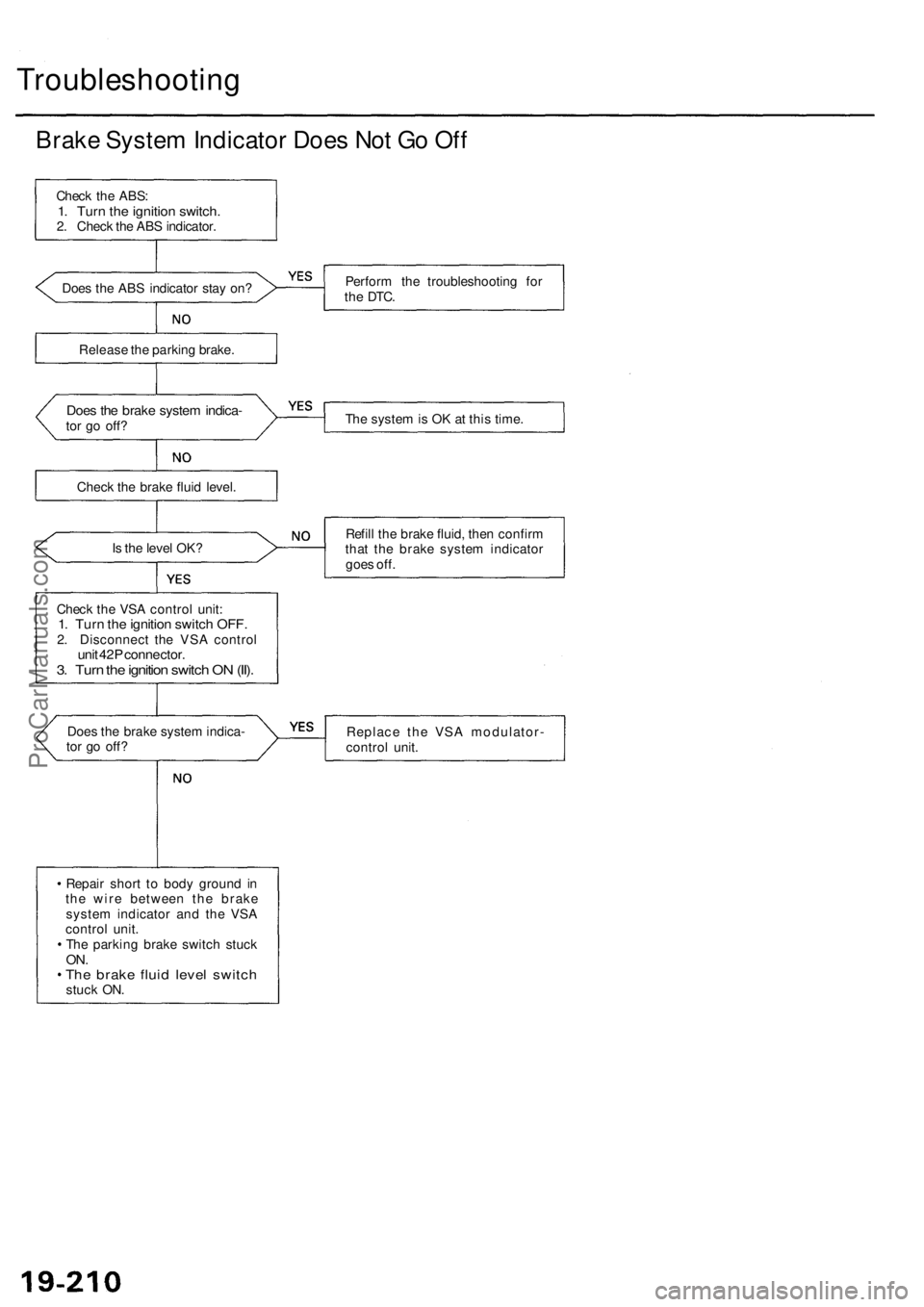
Troubleshooting
Brake System Indicator Does Not Go Off
Check the ABS:
1. Turn the ignition switch.
2. Check the ABS indicator.
Does the ABS indicator stay on?
Perform the troubleshooting for
the
DTC.
Release the parking brake.
Does the brake system indica-
tor go off?
The system is OK at this time.
Check the brake fluid level.
Is the level OK?
Refill the brake fluid, then confirm
that the brake system indicator
goes off.
Check the VSA control unit:
1. Turn the ignition switch OFF.
2. Disconnect the VSA control
unit 42P connector.
3. Turn the ignition switch ON (II).
Does the brake system indica-
tor go off?
Replace the VSA modulator-
control unit.
Repair short to body ground in
the wire between the brake
system indicator and the VSA
control unit.
The parking brake switch stuck
ON.
The brake fluid level switch
stuck ON.ProCarManuals.com
Page 1254 of 1954
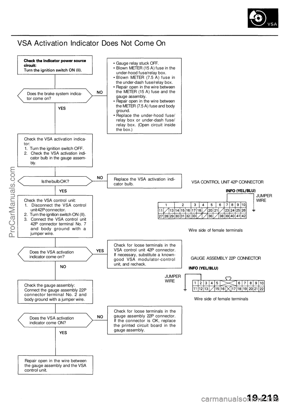
VSA Activation Indicator Does Not Come On
Does the brake system indica-
tor come on?
Check the VSA activation indica-
tor:
1. Turn the ignition switch OFF.
2. Check the VSA activation indi-
cator bulb in the gauge assem-
bly.
Is the bulb OK?
Check the VSA control unit:
1. Disconnect the VSA control
unit 42P connector.
2. Turn the ignition switch ON (II).
3. Connect the VSA control unit
42P connector terminal No. 7
and body ground with a
jumper wire.
Does the VSA activation
indicator come on?
Check the gauge assembly:
Connect the gauge assembly 22P
connector terminal No. 2 and
body ground with a jumper wire.
Does the VSA activation
indicator come ON?
Repair open in the wire between
the gauge assembly and the VSA
control unit.
Gauge relay stuck OFF.
Blown METER (15 A) fuse in the
under-hood fuse/relay box.
Blown METER (7.5 A) fuse in
the under-dash fuse/relay box.
Repair open in the wire between
the METER (15 A) fuse and the
gauge assembly.
Repair open in the wire between
the METER (7.5 A) fuse and body
ground.
Replace the under-hood fuse/
relay box or under-dash fuse/
relay box. (Open circuit inside
the
box.)
Replace the VSA activation indi-
cator bulb.
VSA CONTROL UNIT 42P CONNECTOR
JUMPER
WIRE
Check for loose terminals in the
VSA control unit 42P connector.
If necessary, substitute a known-
good VSA modulator-control
unit, and recheck.
JUMPER
WIRE
Wire side of female terminals
GAUGE ASSEMBLY 22P CONNECTOR
Wire side of female terminals
Check for loose terminals in the
gauge assembly 22P connector.
If the connector is OK, replace
the printed circuit board in the
gauge assembly.ProCarManuals.com