brake ACURA RL KA9 1996 Service User Guide
[x] Cancel search | Manufacturer: ACURA, Model Year: 1996, Model line: RL KA9, Model: ACURA RL KA9 1996Pages: 1954, PDF Size: 61.44 MB
Page 359 of 1954
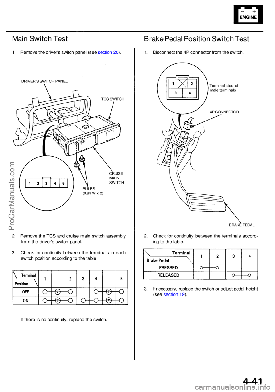
Main Switc h Tes t
1. Remov e th e driver' s switc h pane l (se e sectio n 20 ).
DRIVER' S SWITC H PANE L
TCS SWITC H
CRUISEMAINSWITC H
BULBS(0.84 W x 2)
2. Remov e th e TC S an d cruis e mai n switc h assembl y
fro m th e driver' s switc h panel .
3 . Chec k fo r continuit y betwee n th e terminal s i n eac h
switc h positio n accordin g to th e table .
I f ther e is n o continuity , replac e th e switch .
Brake Peda l Positio n Switc h Tes t
1. Disconnec t th e 4 P connecto r fro m th e switch .
Termina l sid e o fmal e terminal s
4P CONNECTO R
BRAKE PEDA L
2. Chec k fo r continuit y betwee n th e terminal s accord -
in g t o th e table .
3 . I f necessary , replac e th e switc h o r adjus t peda l heigh t
(see section 19 ).
ProCarManuals.com
Page 558 of 1954
PGM-FI Syste m
System Descriptio n
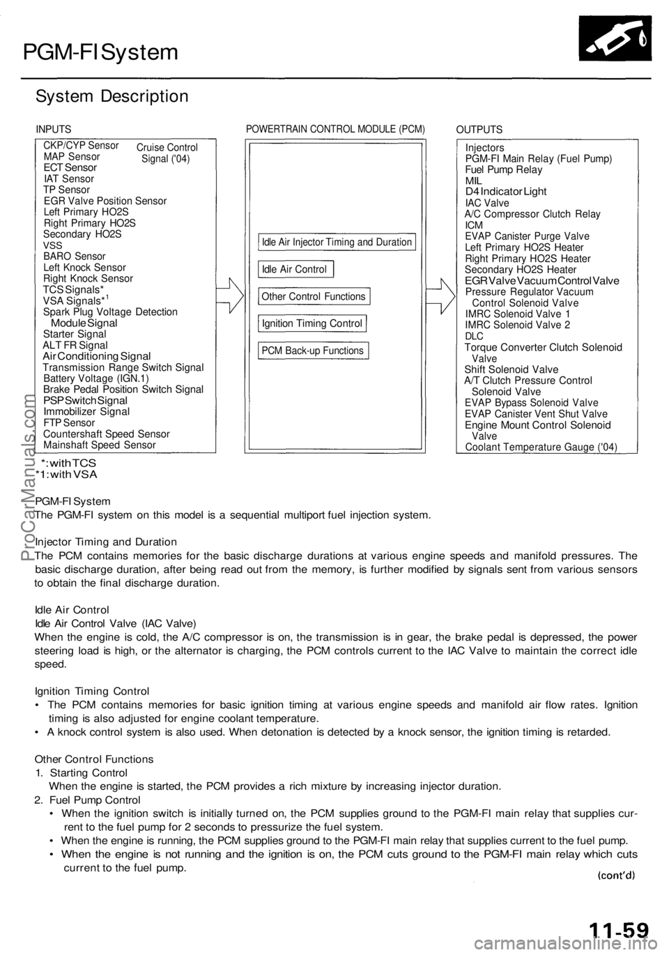
INPUTSPOWERTRAI N CONTRO L MODUL E (PCM )OUTPUT S
CKP/CYP Senso r
Cruise
Control
Signal ('04)MA P Senso rECT Senso rIAT Senso rTP Senso rEGR Valv e Positio n Senso rLeft Primar y HO2 SRight Primar y HO2 SSecondar y HO2 SVSSBAR O Senso rLeft Knoc k Senso rRight Knoc k Senso rTCS Signals *VSA Signals*1
Spar k Plu g Voltag e Detectio nModule Signa lStarte r Signa lALT F R Signa lAir Conditionin g Signa lTransmissio n Rang e Switc h Signa lBattery Voltag e (IGN.1 )Brake Peda l Positio n Switc h Signa lPSP Switc h Signa lImmobilize r Signa lFTP Senso rCountershaf t Spee d Senso rMainshaf t Spee d Senso r
Idle Ai r Injecto r Timin g an d Duratio n
Other Contro l Function s
Ignition Timin g Contro l
PCM Back-u p Function s
InjectorsPGM-FI Mai n Rela y (Fue l Pump )Fuel Pum p Rela yMILD4 Indicato r Ligh tIAC Valv eA/C Compresso r Clutc h Rela yICMEVA P Caniste r Purg e Valv eLeft Primar y HO2 S Heate rRight Primar y HO2 S Heate rSecondar y HO2 S Heate rEGR Valv e Vacuu m Contro l Valv ePressur e Regulato r Vacuu mControl Solenoi d Valv eIMRC Solenoi d Valv e 1IMR C Solenoi d Valv e 2DL CTorqu e Converte r Clutc h Solenoi dValveShift Solenoi d Valv eA/T Clutc h Pressur e Contro lSolenoid Valv eEVAP Bypas s Solenoi d Valv eEVAP Caniste r Ven t Shu t Valv eEngin e Moun t Contro l Solenoi dValve
PGM-F I Syste m
Th e PGM-F I syste m o n thi s mode l i s a sequentia l multipor t fue l injectio n system .
Injecto r Timin g an d Duratio n
Th e PC M contain s memorie s fo r th e basi c discharg e duration s a t variou s engin e speed s an d manifol d pressures . Th e
basi c discharg e duration , afte r bein g rea d ou t fro m th e memory , i s furthe r modifie d b y signal s sen t fro m variou s sensor s
t o obtai n th e fina l discharg e duration .
Idl e Ai r Contro l
Idl e Ai r Contro l Valv e (IA C Valve )
Whe n th e engin e i s cold , th e A/ C compresso r i s on , th e transmissio n i s i n gear , th e brak e peda l i s depressed , th e powe r
steerin g loa d i s high , o r th e alternato r i s charging , th e PC M control s curren t t o th e IA C Valv e t o maintai n th e correc t idl e
speed .
Ignition Timin g Contro l
• Th e PC M contain s memorie s fo r basi c ignitio n timin g a t variou s engin e speed s an d manifol d ai r flo w rates . Ignitio n
timin g i s als o adjuste d fo r engin e coolan t temperature .
• A knoc k contro l syste m is als o used . Whe n detonatio n i s detecte d b y a knoc k sensor , th e ignitio n timin g is retarded .
Othe r Contro l Function s
1 . Startin g Contro l
Whe n th e engin e is started , th e PC M provide s a ric h mixtur e b y increasin g injecto r duration .
2 . Fue l Pum p Contro l
• Whe n th e ignitio n switc h i s initiall y turne d on , th e PC M supplie s groun d t o th e PGM-F I mai n rela y tha t supplie s cur -
ren t t o th e fue l pum p fo r 2 second s t o pressuriz e th e fue l system .
• Whe n th e engin e is running , th e PC M supplie s groun d to th e PGM-F I mai n rela y tha t supplie s current to th e fue l pump .
• Whe n th e engin e is no t runnin g an d th e ignitio n i s on , th e PC M cut s groun d t o th e PGM-F I mai n rela y whic h cut s
curren t t o th e fue l pump .
*: wit h TC S*1: wit h VS A
Idle Ai r Contro l
Coolant Temperature Gauge ('04)
ProCarManuals.com
Page 621 of 1954
Idle Contro l Syste m
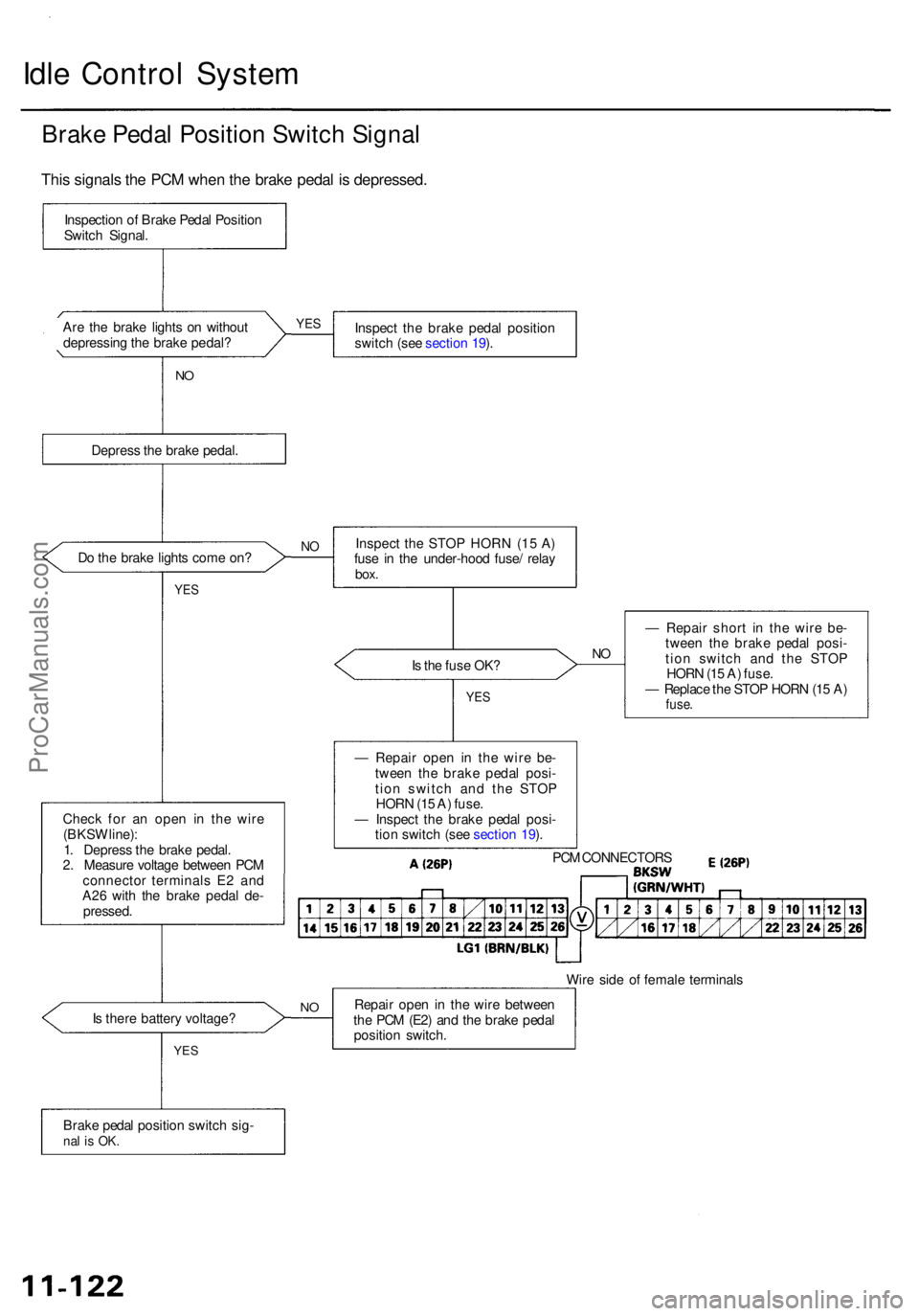
Brake Peda l Positio n Switc h Signa l
Are th e brak e light s o n withou t
depressin g th e brak e pedal ? Inspec
t th e brak e peda l positio n
switc h (se e sectio n 19 ).
N O
Depres s th e brak e pedal .
D o th e brak e light s com e on ?
YES
Is th e fus e OK ?NO
Chec k fo r a n ope n i n th e wir e
(BKS W line) :
1 . Depres s th e brak e pedal .
2 . Measur e voltag e betwee n PC M
connecto r terminal s E 2 an d
A2 6 wit h th e brak e peda l de -
pressed . —
Repai r shor t i n th e wire be-
twee n th e brak e peda l posi -
tio n switc h an d th e STO P
HOR N (1 5 A ) fuse .
— Replac e th e STO P HOR N (1 5 A )
fuse .
Wire sid e o f femal e terminal s
I s ther e batter y voltage ? Repai
r ope n in th e wir e betwee n
th e PC M (E2 ) an d th e brak e peda l
positio n switch .
Brak e peda l positio n switc h sig -
nal i s OK .
YES
NO
— Repai r ope n i n th e wir e be -
twee n th e brak e peda l posi -
tio n switc h an d th e STO P
HOR N (1 5 A ) fuse .
— Inspec t th e brak e peda l posi -
tio n switc h (se e sectio n 19 ).
PC M CONNECTOR S
YES
NOInspec t th e STO P HOR N (1 5 A )
fus e i n th e under-hoo d fuse / rela y
box.
YES
Inspectio n o f Brak e Peda l Positio n
Switc h Signal .
This signal s th e PC M whe n th e brak e peda l i s depressed .
ProCarManuals.com
Page 730 of 1954

Grade Logic Control System
How it works:
The PCM compares actual driving conditions with driving conditions memorized in the PCM, based on the input from the
vehicle speed sensor, throttle position sensor, engine coolant temperature sensor, barometric pressure sensor, brake
pedal position switch signal and shift lever position signal, to control shifting while a vehicle is ascending or descending a
slope.ProCarManuals.com
Page 731 of 1954
Description
Electronic Control System (cont'd)
Ascending Control
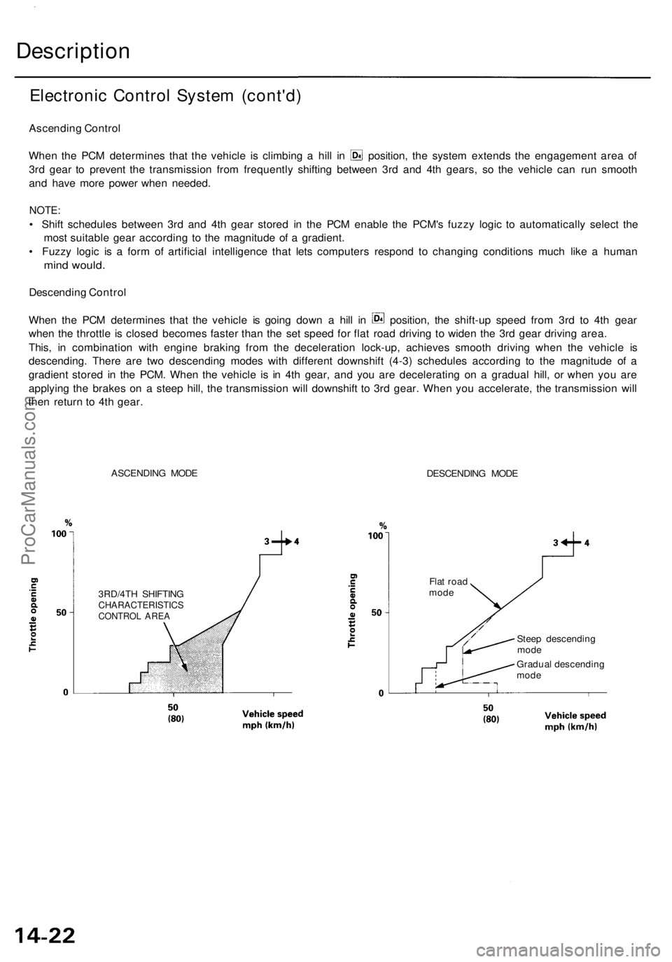
When the PCM determines that the vehicle is climbing a hill in position, the system extends the engagement area of
3rd gear to prevent the transmission from frequently shifting between 3rd and 4th gears, so the vehicle can run smooth
and have more power when needed.
NOTE:
• Shift schedules between 3rd and 4th gear stored in the PCM enable the PCM's fuzzy logic to automatically select the
most suitable gear according to the magnitude of a gradient.
• Fuzzy logic is a form of artificial intelligence that lets computers respond to changing conditions much like a human
mind would.
Descending Control
When the PCM determines that the vehicle is going down a hill in position, the shift-up speed from 3rd to 4th gear
when the throttle is closed becomes faster than the set speed for flat road driving to widen the 3rd gear driving area.
This, in combination with engine braking from the deceleration lock-up, achieves smooth driving when the vehicle is
descending. There are two descending modes with different downshift (4-3) schedules according to the magnitude of a
gradient stored in the PCM. When the vehicle is in 4th gear, and you are decelerating on a gradual hill, or when you are
applying the brakes on a steep hill, the transmission will downshift to 3rd gear. When you accelerate, the transmission will
then return to 4th gear.
ASCENDING MODE
DESCENDING MODE
3RD/4TH SHIFTING
CHARACTERISTICS
CONTROL AREA
Flat road
mode
Steep descending
mode
Gradual descending
modeProCarManuals.com
Page 799 of 1954
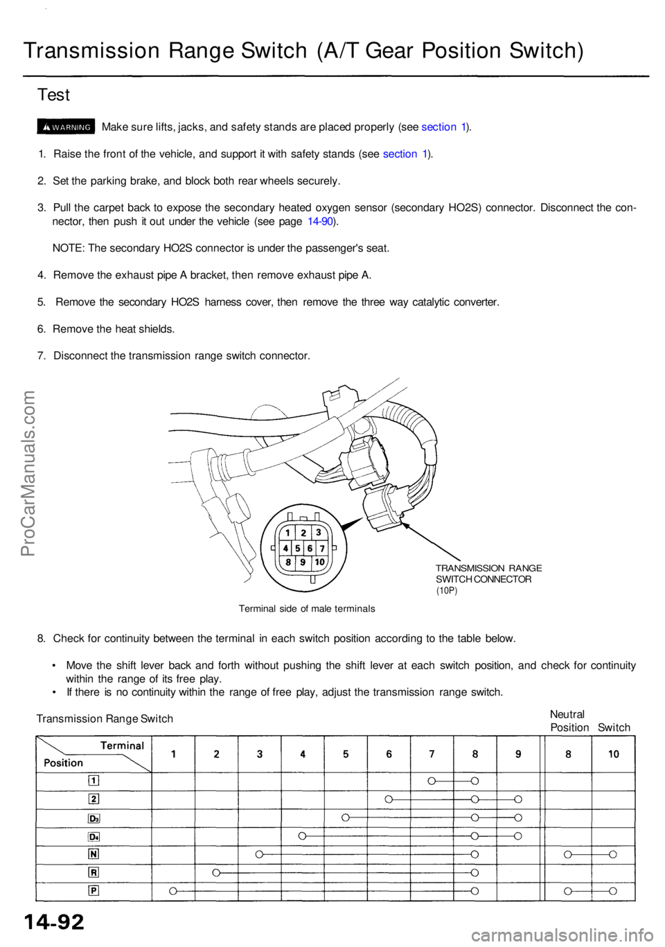
Transmission Rang e Switc h (A/ T Gea r Positio n Switch )
Test
Mak e sur e lifts , jacks , an d safet y stand s ar e place d properl y (se e sectio n 1 ).
1 . Rais e th e fron t o f th e vehicle , an d suppor t i t wit h safet y stand s (se e sectio n 1 ).
2 . Se t th e parkin g brake , an d bloc k bot h rea r wheel s securely .
3 . Pul l th e carpe t bac k t o expos e th e secondar y heate d oxyge n senso r (secondar y HO2S ) connector . Disconnec t th e con -
nector , the n pus h it ou t unde r th e vehicl e (se e pag e 14-90 ).
NOTE : Th e secondar y HO2 S connecto r i s unde r th e passenger' s seat .
4 . Remov e th e exhaus t pip e A bracket , the n remov e exhaus t pip e A .
5 . Remov e th e secondar y HO2 S harnes s cover , the n remov e th e thre e wa y catalyti c converter .
6 . Remov e th e hea t shields .
7 . Disconnec t th e transmissio n rang e switc h connector .
TRANSMISSIO N RANG ESWITCH CONNECTO R(10P)
Termina l sid e o f mal e terminal s
8. Chec k fo r continuit y betwee n th e termina l i n eac h switc h positio n accordin g t o th e tabl e below .
• Mov e th e shif t leve r bac k an d fort h withou t pushin g th e shif t leve r a t eac h switc h position , an d chec k fo r continuit y
withi n th e rang e o f it s fre e play .
• I f ther e i s n o continuit y withi n th e rang e o f fre e play , adjus t th e transmissio n rang e switch .
Neutral
Positio n Switc h
Transmissio
n Rang e Switc h
ProCarManuals.com
Page 800 of 1954
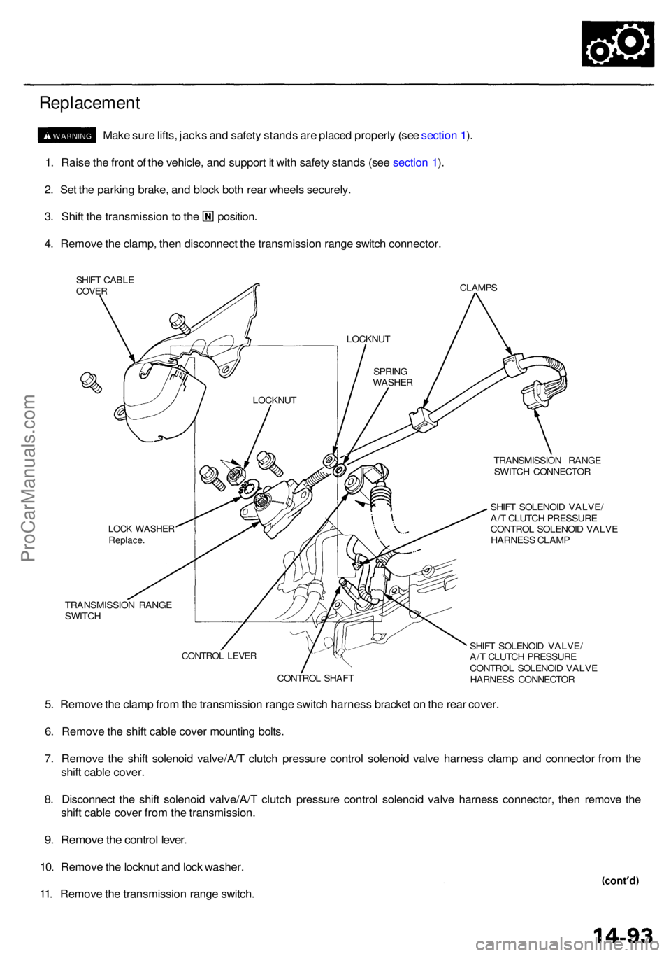
Replacement
Make sur e lifts , jack s an d safet y stand s ar e place d properl y (se e sectio n 1 ).
1 . Rais e th e fron t o f th e vehicle , an d suppor t i t wit h safet y stand s (se e sectio n 1 ).
2 . Se t th e parkin g brake , an d bloc k bot h rea r wheel s securely .
3. Shif t th e transmissio n to th e position .
4 . Remov e th e clamp , the n disconnec t th e transmissio n rang e switc h connector .
SHIFT CABL ECOVERCLAMP S
TRANSMISSIO N RANG E
SWITC H CONNECTO R
SHIF T SOLENOI D VALVE /
A/ T CLUTC H PRESSUR E
CONTRO L SOLENOI D VALV E
HARNES S CLAM P
TRANSMISSIO N RANG E
SWITC H
SHIFT SOLENOI D VALVE /
A/ T CLUTC H PRESSUR E
CONTRO L SOLENOI D VALV E
HARNES S CONNECTO R
5. Remov e th e clam p fro m th e transmissio n rang e switc h harnes s bracke t o n th e rea r cover .
6 . Remov e th e shif t cabl e cove r mountin g bolts .
7 . Remov e th e shif t solenoi d valve/A/ T clutc h pressur e contro l solenoi d valv e harnes s clam p an d connecto r fro m th e
shif t cabl e cover .
8 . Disconnec t th e shif t solenoi d valve/A/ T clutc h pressur e contro l solenoi d valv e harnes s connector , the n remov e th e
shif t cabl e cove r fro m th e transmission .
9. Remov e th e contro l lever .
10. Remov e th e locknu t an d loc k washer .
11 . Remov e th e transmissio n rang e switch .
LOCKNU T
LOCK WASHE RReplace.
CONTRO L SHAF T
CONTRO L LEVE R
SPRIN G
WASHE R
LOCKNU
T
ProCarManuals.com
Page 813 of 1954
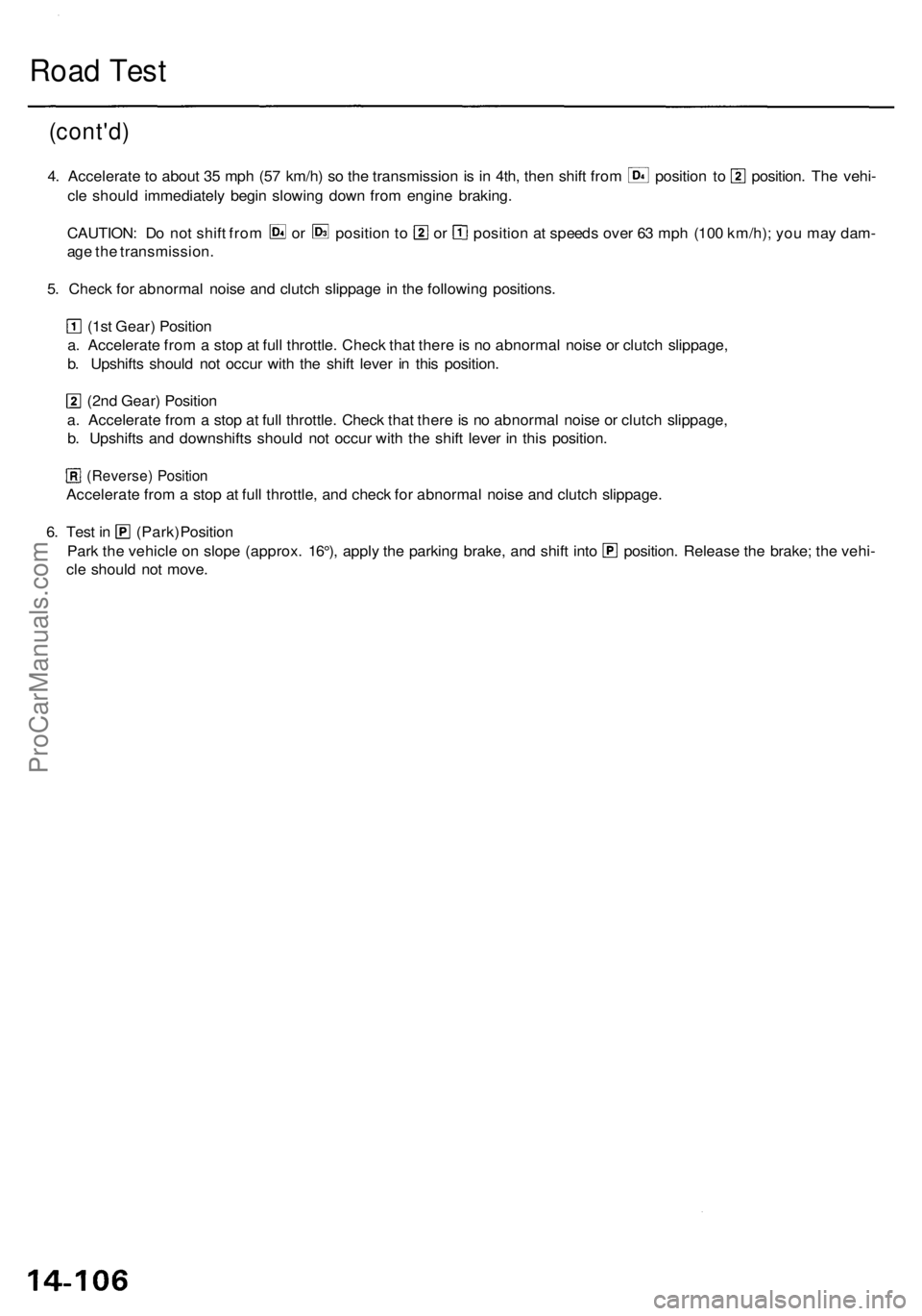
Road Tes t
(cont'd )
4. Accelerat e to abou t 3 5 mp h (5 7 km/h ) s o th e transmissio n is i n 4th , the n shif t fro m positio n t o position . Th e vehi -
cl e shoul d immediatel y begi n slowin g dow n fro m engine braking .
CAUTION : D o no t shif t fro m o r positio n to o r positio n a t speed s ove r 6 3 mp h (10 0 km/h) ; yo u ma y dam -
ag e th e transmission .
5 . Chec k fo r abnorma l nois e an d clutc h slippag e in th e followin g positions .
(1st Gear ) Positio n
a . Accelerat e fro m a sto p a t ful l throttle . Chec k tha t ther e is n o abnorma l nois e o r clutc h slippage ,
b . Upshift s shoul d no t occu r wit h th e shif t leve r i n thi s position .
(2nd Gear ) Positio n
a . Accelerat e fro m a sto p a t ful l throttle . Chec k tha t ther e is n o abnorma l nois e o r clutc h slippage ,
b . Upshift s an d downshift s shoul d no t occu r wit h th e shif t leve r i n thi s position .
(Reverse ) Positio n
Accelerat e fro m a sto p a t ful l throttle , an d chec k fo r abnorma l nois e an d clutc h slippage .
6. Tes t i n (Park ) Positio n
Park th e vehicl e o n slop e (approx . 16°) , appl y th e parkin g brake , an d shif t int o position . Releas e th e brake ; th e vehi -
cl e shoul d no t move .
ProCarManuals.com
Page 814 of 1954
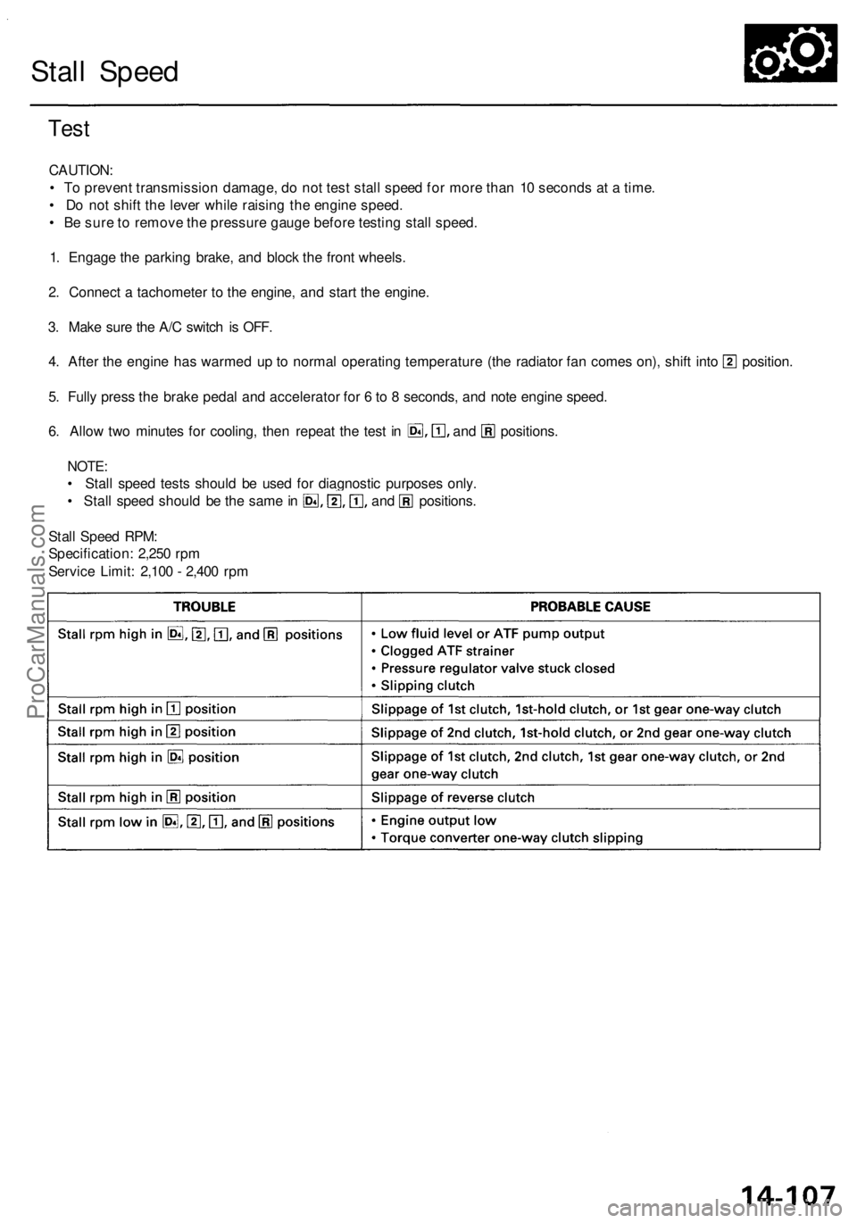
Stall Speed
Test
CAUTION:
• To prevent transmission damage, do not test stall speed for more than 10 seconds at a time.
• Do not shift the lever while raising the engine speed.
• Be sure to remove the pressure gauge before testing stall speed.
1. Engage the parking brake, and block the front wheels.
2. Connect a tachometer to the engine, and start the engine.
3. Make sure the A/C switch is OFF.
4. After the engine has warmed up to normal operating temperature (the radiator fan comes on), shift into position.
5. Fully press the brake pedal and accelerator for 6 to 8 seconds, and note engine speed.
6. Allow two minutes for cooling, then repeat the test in and positions.
NOTE:
• Stall speed tests should be used for diagnostic purposes only.
• Stall speed should be the same in and positions.
Stall Speed RPM:
Specification: 2,250 rpm
Service Limit: 2,100 - 2,400 rpmProCarManuals.com
Page 816 of 1954

Pressure Testin g
• Whil e testing , b e carefu l o f th e rotatin g fron t wheels .
• Mak e sur e lifts , jack s an d safet y stand s ar e place d properl y (se e sectio n 1 ).
CAUTION :
• Befor e testing , b e sur e th e transmissio n flui d is fille d to th e prope r level .
• War m up th e engin e befor e testing .
1 . Rais e th e fron t o f th e vehicle , an d suppor t i t wit h safet y stands .
2 . Se t th e parkin g brake , an d bloc k rea r wheel s securely .
3. Allo w th e fron t wheel s to rotat e freely .
4. War m u p th e engin e (th e radiator fan come s on) , the n sto p an d connec t a tachometer .
5 . Connec t th e specia l too l t o lin e pressur e inspectio n hole .
TORQUE : 1 8 N- m (1. 8 kgf-m , 1 3 Ibf-ft )
CAUTION : Connec t th e oi l pressur e gaug e securely , b e sur e no t t o allo w dus t an d othe r foreig n particle s t o ente r th e
inspectio n hole .
LINE PRESSUR E
INSPECTIO N HOL E
A/ T OI L PRESSUR E GAUG E
SE T W/PANE L
07406-002040 0
A/T LO W PRESSUR E
GAUG E W/PANE L
07406-007030 0
A/T PRESSUR E HOS E
ADAPTE R
07MAJ-PY4012 0(4 Required )
A/ T PRESSUR E HOSE ,
2210 mm07MAJ-PY4011 A(4 Required )
ProCarManuals.com