mirror ACURA RL KA9 1996 Service Owner's Manual
[x] Cancel search | Manufacturer: ACURA, Model Year: 1996, Model line: RL KA9, Model: ACURA RL KA9 1996Pages: 1954, PDF Size: 61.44 MB
Page 1637 of 1954
Driving Positio n Memor y Syste m (DPMS )
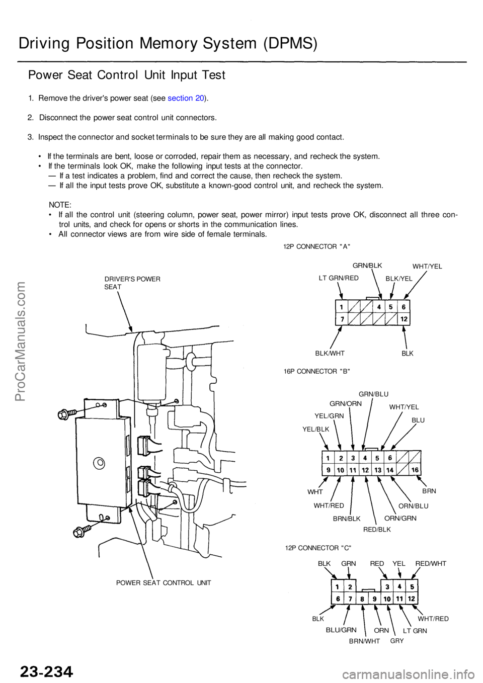
Power Sea t Contro l Uni t Inpu t Tes t
1. Remov e th e driver' s powe r sea t (se e sectio n 20 ).
2 . Disconnec t th e powe r sea t contro l uni t connectors .
3 . Inspec t th e connecto r an d socke t terminal s t o b e sur e the y ar e al l makin g goo d contact .
• I f th e terminal s ar e bent , loos e o r corroded , repai r the m a s necessary , an d rechec k th e system .
• I f th e terminal s loo k OK , mak e th e followin g inpu t test s a t th e connector .
I f a tes t indicate s a problem , fin d an d correc t th e cause , the n rechec k th e system .
If al l th e inpu t test s prov e OK , substitut e a known-goo d contro l unit , an d rechec k th e system .
NOTE:
• I f al l th e contro l uni t (steerin g column , powe r seat , powe r mirror ) inpu t test s prov e OK , disconnec t al l thre e con -
tro l units , an d chec k fo r open s o r short s i n th e communicatio n lines .
• Al l connecto r view s ar e fro m wir e sid e o f femal e terminals .
12P CONNECTO R "A "
POWE R SEA T CONTRO L UNI T
DRIVER'
S POWE R
SEA T
BLK/WHT
BLK
LT GRN/RE D
GRN/BLK
BLK/YE L
WHT/YE L
16 P CONNECTO R "B "
GRN/BL U
WHT/YE L
BLU
GRN/OR N
YEL/GRN
YEL/BLK
WHT
WHT/RE D
BRN
ORN/BL U
ORN/GR N
RED/BLK
BRN/BLK
12 P CONNECTO R "C "
BLK GR N RE D YE L RED/WH T
BLK
BLU/GR N
BRN/WH T
ORNLT GR N
WHT/RE D
GRY
ProCarManuals.com
Page 1641 of 1954
Driving Positio n Memor y Syste m (DPMS )
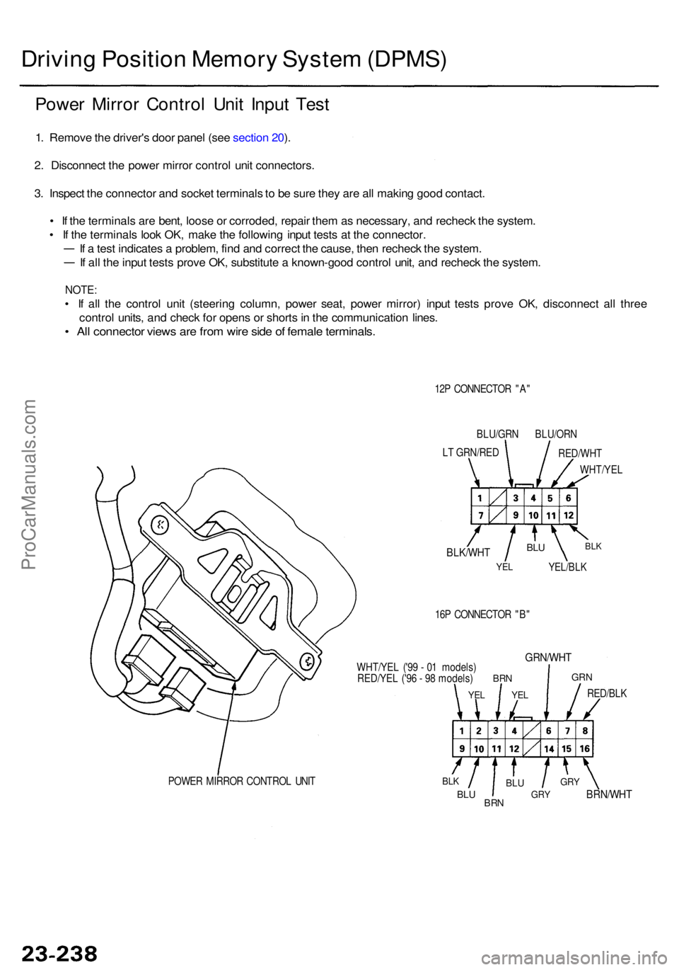
Power Mirro r Contro l Uni t Inpu t Tes t
1. Remov e th e driver' s doo r pane l (se e sectio n 20 ).
2 . Disconnec t th e powe r mirro r contro l uni t connectors .
3 . Inspec t th e connecto r an d socke t terminal s to b e sur e the y ar e al l makin g goo d contact .
• I f th e terminal s ar e bent , loos e o r corroded , repai r the m as necessary , an d rechec k th e system .
• I f th e terminal s loo k OK , mak e th e followin g inpu t test s a t th e connector .
I f a tes t indicate s a problem , fin d an d correc t th e cause , the n rechec k th e system .
If al l th e inpu t test s prov e OK , substitut e a known-goo d contro l unit , an d rechec k th e system .
NOTE:
• I f al l th e contro l uni t (steerin g column , powe r seat , powe r mirror ) inpu t test s prov e OK , disconnec t al l thre e
contro l units , an d chec k fo r open s o r short s in th e communicatio n lines .
• Al l connecto r view s ar e fro m wir e sid e o f femal e terminals .
12P CONNECTO R "A "
BLU/GR N BLU/OR N
L T GRN/RE D
RED/WHT
WHT/YE L
BLK/WHT
YEL
BLU
YEL/BL K
BLK
16P CONNECTO R "B "
WHT/YE L ('9 9 - 0 1 models )
RED/YE L ('9 6 - 9 8 models )
YEL
BR N
YEL
GRN/WH T
GRN
RED/BL K
BRN/WH T
GRY
GR YBLU
BR NBLU
BLKPOWE R MIRRO R CONTRO L UNI T
ProCarManuals.com
Page 1721 of 1954
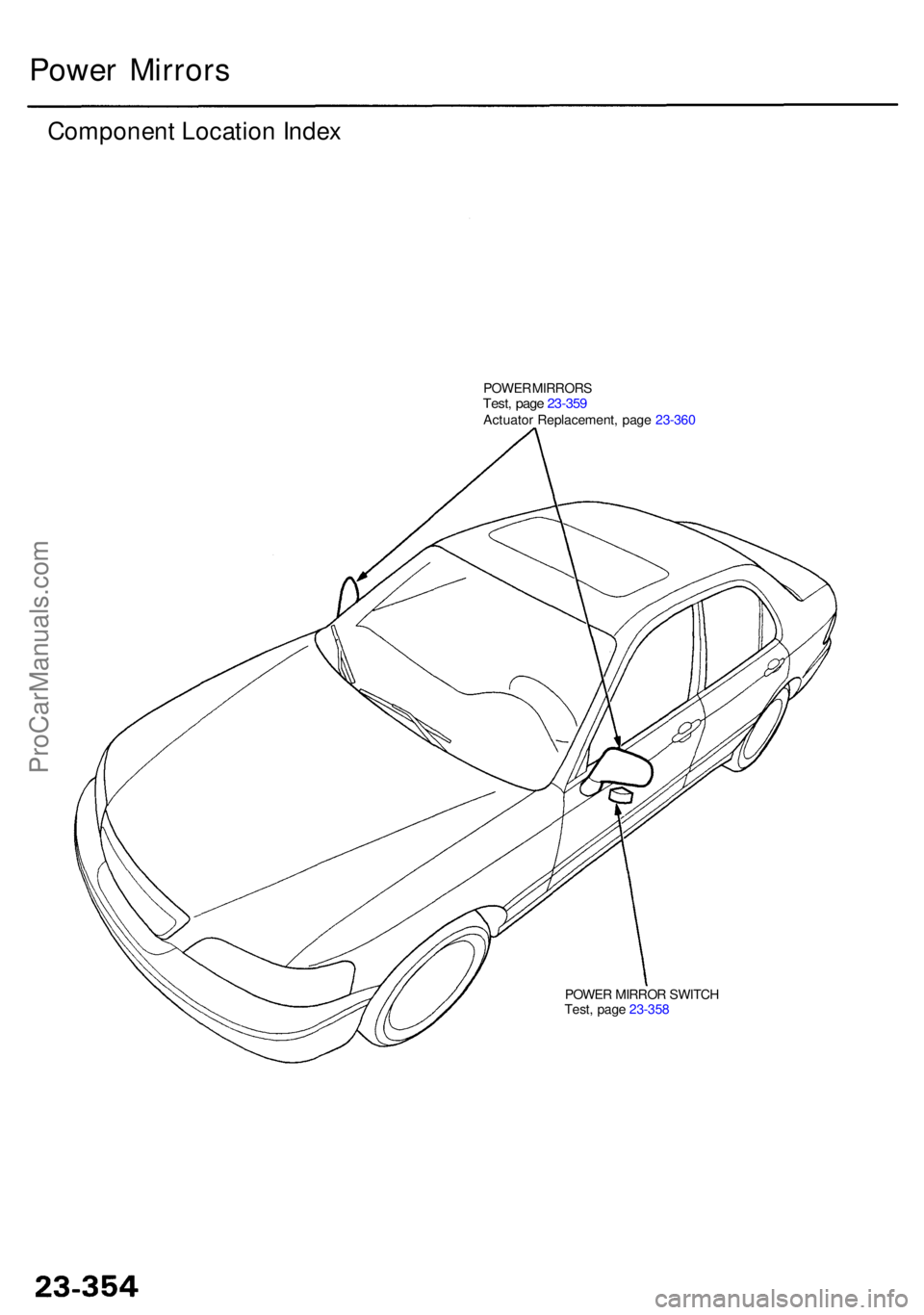
POWER MIRRO R SWITC H
Test , pag e 23-35 8
Powe r Mirror s
Componen t Locatio n Inde x
POWE R MIRROR STest, pag e 23-35 9Actuato r Replacement , pag e 23-36 0
ProCarManuals.com
Page 1722 of 1954
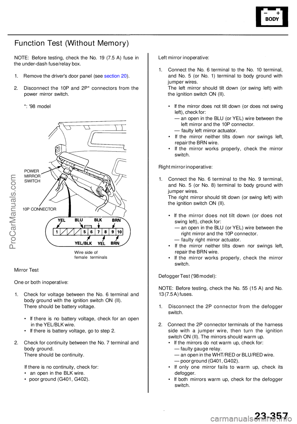
Function Tes t (Withou t Memory )
NOTE: Befor e testing , chec k th e No . 1 9 (7. 5 A ) fus e i n
th e under-das h fuse/rela y box .
1 . Remov e th e driver' s doo r pane l (se e sectio n 20 ).
2 . Disconnec t th e 10 P an d 2P * connector s fro m th e
powe r mirro r switch .
* : '9 8 mode l
POWE RMIRRO RSWITCH
10 P CONNECTO R
Mirror Tes t
On e o r bot h inoperative :
1 . Chec k fo r voltag e betwee n th e No . 6 termina l an d
bod y groun d wit h th e ignitio n switc h O N (II) .
Ther e shoul d b e batter y voltage .
• I f ther e i s n o batter y voltage , chec k fo r a n ope n
i n th e YEL/BL K wire .
• I f ther e is batter y voltage , g o to ste p 2 .
2 . Chec k fo r continuit y betwee n th e No . 7 termina l an d
bod y ground .
Ther e shoul d b e continuity .
I f ther e is n o continuity , chec k for :
• a n ope n in th e BL K wire .
• poo r groun d (G401 , G402) . Lef
t mirro r inoperative :
1 . Connec t th e No . 6 termina l t o th e No . 1 0 terminal ,
an d No . 5 (o r No . 1 ) termina l t o bod y groun d wit h
jumpe r wires .
Th e lef t mirro r shoul d til t dow n (o r swin g left ) wit h
th e ignitio n switc h O N (II) .
• I f th e mirro r doe s no t til t dow n (o r doe s no t swin g
left) , chec k for :
— an ope n in th e BL U (o r YEL ) wir e betwee n th e
lef t mirro r an d th e 10 P connector .
— fault y lef t mirro r actuator .
• I f th e mirro r neithe r tilt s dow n no r swing s left ,
repai r th e BR N wire .
• I f th e mirro r work s properly , chec k th e mirro r
switch .
Righ t mirro r inoperative :
1 . Connec t th e No . 6 termina l t o th e No . 9 terminal ,
an d No . 5 (o r No . 8 ) termina l t o bod y groun d wit h
jumpe r wires .
Th e righ t mirro r shoul d til t dow n (o r swin g left ) wit h
th e ignitio n switc h O N (II) .
• I f th e mirro r doe s no t til t dow n (o r doe s no t
swin g left) , chec k for :
— an ope n in th e BL U (o r YEL ) wir e betwee n th e
righ t mirro r an d th e 10 P connector .
— fault y righ t mirro r actuator .
• I f th e mirro r neithe r tilt s dow n no r swing s left ,
repai r th e BR N wire .
• I f th e mirro r work s properly , chec k th e mirro r
switch .
Defogge r Tes t ('9 8 model) :
NOTE : Befor e testing , chec k th e No . 5 5 (1 5 A ) an d No .
1 3 (7. 5 A ) fuses .
1 . Disconnec t th e 2 P connecto r fro m th e defogge r
switch .
2 . Connec t th e 2 P connecto r terminal s o f th e harnes s
sid e wit h a jumpe r wire , the n tur n th e ignitio n
switc h O N (II) . Th e mirror s shoul d war m up .
• I f th e mirror s d o no t war m up , chec k for :
— fault y gaug e relay .
— an ope n in th e WHT/RE D o r BLU/RE D wire .
— poo r groun d (G401 , G402) .
• I f onl y on e mirro r fail s t o war m up , chec k it s
defogger .
• I f bot h mirror s war m up , chec k fo r th e defogge r
switch .
Wire sid e o ffemal e terminal s
ProCarManuals.com
Page 1723 of 1954
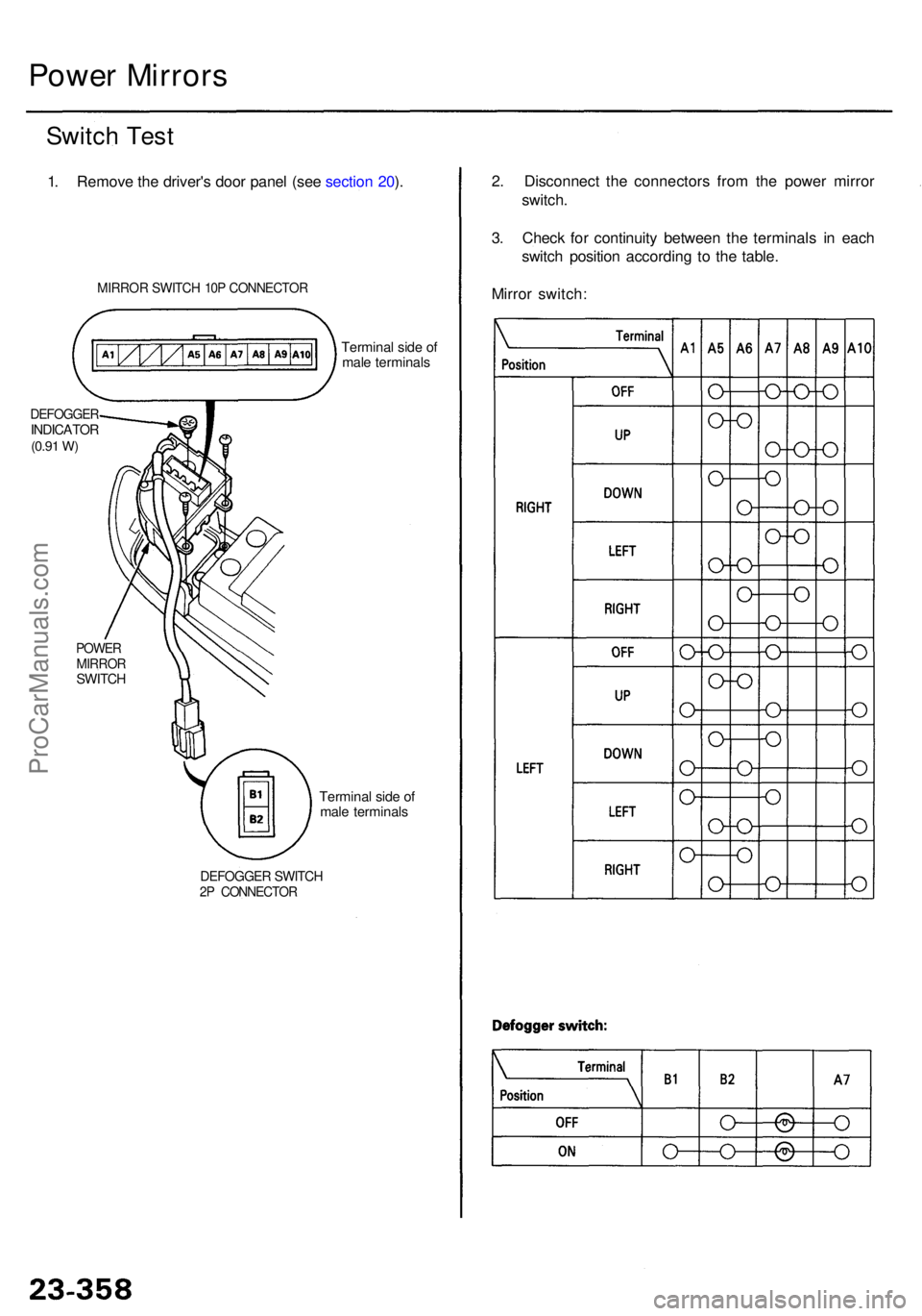
2. Disconnec t th e connector s fro m th e powe r mirro r
switch .
3 . Chec k fo r continuit y betwee n th e terminal s i n eac h
switc h positio n accordin g t o th e table .
Mirro r switch :
Power Mirror s
Switch Tes t
1. Remov e th e driver' s doo r pane l (se e sectio n 20 ).
MIRRO R SWITC H 10 P CONNECTO R
Terminal sid e o f
mal e terminal s
DEFOGGE RINDICATOR(0.91 W)
POWE RMIRRO RSWITCH
DEFOGGE R SWITC H2P CONNECTO R
Terminal sid e o f
mal e terminal s
ProCarManuals.com
Page 1724 of 1954
![ACURA RL KA9 1996 Service Owners Manual Power Mirro r Tes t
1. Remov e th e doo r pane l (se e sectio n 20 ).
POWE R MIRRO R10P [8P ]CONNECTO R
2. Disconnec t th e 10 P [8P ] connecto r fro m th e powe r
mirro r actuator .
3 . Chec k actuat](/img/32/56992/w960_56992-1723.png "ACURA RL KA9 1996 Service Owners Manual Power Mirro r Tes t
1. Remov e th e doo r pane l (se e sectio n 20 ).
POWE R MIRRO R10P [8P ]CONNECTO R
2. Disconnec t th e 10 P [8P ] connecto r fro m th e powe r
mirro r actuator .
3 . Chec k actuat")
Power Mirro r Tes t
1. Remov e th e doo r pane l (se e sectio n 20 ).
POWE R MIRRO R10P [8P ]CONNECTO R
2. Disconnec t th e 10 P [8P ] connecto r fro m th e powe r
mirro r actuator .
3 . Chec k actuato r operatio n b y connectin g powe r an d
groun d accordin g t o th e table .
[ ] : Withou t memor y
Defogge r Test :
4 . Chec k fo r continuit y betwee n th e No . 3 [No . 2 ] an d
No . 4 [No . 3 ] terminal s o f th e 10 P [8P ] connector .
Ther e shoul d b e continuity .
5 . I f th e mirro r fail s t o wor k properly , replac e th e mir -
ror actuator or mirror sub assembly (see page
23-360 ).
[ ] : Withou t memor y ('9 8 model )
With memor y
Wire sid e o f
femal e terminal s
Withou t memor y
Wire sid e o f
femal e terminal s
ProCarManuals.com
Page 1725 of 1954
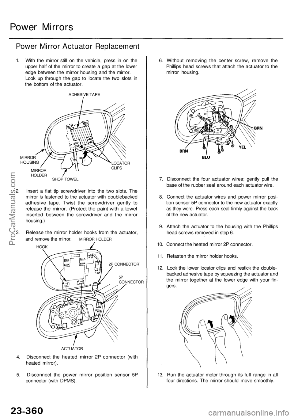
4. Disconnec t th e heate d mirro r 2 P connecto r (wit h
heate d mirror) .
5 . Disconnec t th e powe r mirro r positio n senso r 5 P
connecto r (wit h DPMS) .
Power Mirror s
Power Mirro r Actuato r Replacemen t
1. Wit h th e mirro r stil l o n th e vehicle , pres s i n o n th e
uppe r hal f o f th e mirro r t o creat e a ga p a t th e lowe r
edg e betwee n th e mirro r housin g an d th e mirror .
Loo k u p throug h th e ga p t o locat e th e tw o slot s i n
th e botto m o f th e actuator .
ADHESIV E TAP E
MIRRO RHOUSIN GLOCATO RCLIPS
SHO P TOWE L
MIRRO
R
HOLDE R
2. Inser t a fla t ti p screwdrive r int o th e tw o slots . Th e
mirro r i s fastene d t o th e actuato r wit h doublebacke d
adhesiv e tape . Twis t th e screwdrive r gentl y t o
releas e th e mirror . (Protec t th e pain t wit h a towe l
inserte d betwee n th e screwdrive r an d th e mirro r
housing. )
3 . Releas e th e mirro r holde r hook s fro m th e actuator ,
and remov e th e mirror . MIRRO R HOLDE R
HOOK
2P CONNECTOR
5PCONNECTO R
ACTUATOR
13. Ru n th e actuato r moto r throug h it s ful l rang e i n al l
fou r directions . Th e mirro r shoul d mov e smoothly .
6
. Withou t removin g th e cente r screw , remov e th e
Phillip s hea d screw s tha t attac h th e actuato r t o th e
mirro r housing .
7 . Disconnec t th e fou r actuato r wires ; gentl y pul l th e
bas e o f th e rubbe r sea l aroun d eac h actuato r wire .
8 . Connec t th e actuato r wire s an d powe r mirro r posi -
tio n senso r 5 P connecto r t o th e ne w actuato r exactl y
a s the y were . Pres s eac h sea l firml y agains t th e bac k
o f th e ne w actuator .
9 . Attac h th e actuato r t o th e housin g wit h th e Phillip s
hea d screw s remove d in ste p 6 .
10 . Connec t th e heate d mirro r 2 P connector .
11 . Refaste n th e mirro r holde r hooks .
12. Loc k th e lowe r locato r clip s an d restic k th e double -
backed adhesiv e tap e b y squeezin g th e actuato r an d
th e mirro r togethe r a t th e lowe r edg e wit h you r fin -
gers .
ProCarManuals.com