fuse box ACURA RL KA9 1996 Service Manual PDF
[x] Cancel search | Manufacturer: ACURA, Model Year: 1996, Model line: RL KA9, Model: ACURA RL KA9 1996Pages: 1954, PDF Size: 61.44 MB
Page 1177 of 1954
Troubleshooting
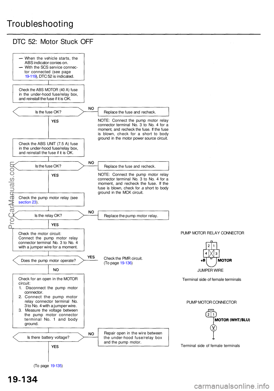
DTC 52 : Moto r Stuc k OF F
Whe n th e vehicl e starts , th eAB S indicato r conie s on .Wit h th e SC S servic e connec -
to r connecte d (se e pag e
19-119 ), DT C 52 is indicated .
Check th e AB S MOTO R (4 0 A ) fus ein th e under-hoo d fuse/rela y box ,and reinstal l th e fus e if i t i s OK .
Is th e fus e OK ?
Chec k th e AB S UNI T (7. 5 A ) fus e
in th e under-hoo d fuse/rela y box ,and reinstal l th e fus e if i t i s OK .
I s th e fus e OK ?
Chec k th e pum p moto r rela y (se e
sectio n 23 ).
I s th e rela y OK ?
Chec k th e moto r circuit :
Connec t th e pum p moto r rela y
connecto r termina l No . 3 to No . 4
wit h a jumpe r wir e fo r a moment .
Does th e pum p moto r operate ?
Chec k fo r a n ope n in th e MOTO R
circuit :
1 . Disconnec t th e pum p moto r
connector .2. Connec t th e pum p moto rrelay connecto r termina l No .3 to No . 4 wit h a jumpe r wire .3. Measur e th e voltag e betwee n
th e pum p moto r connecto r
terminal No . 1 an d bod yground .
Is ther e batter y voltage ?
(T o pag e 19-135 ) Replac
e th e fus e an d recheck .
NOTE : Connec t th e pum p moto r rela y
connecto r termina l No . 3 to No . 4 fo r a
moment , an d rechec k th e fuse . I f th e fus e
i s blown , chec k fo r a shor t t o bod y
groun d i n th e moto r powe r sourc e circuit .
Replac e th e fus e an d recheck .
NOTE: Connec t th e pum p moto r rela y
connecto r termina l No . 3 to No . 4 fo r a
moment , an d rechec k th e fuse . I f th efus e i s blown , chec k fo r a shor t t o bod y
groun d i n th e MC K circuit .
Replac e th e pum p moto r relay .
PUMP MOTO R RELA Y CONNECTO R
Chec k th e PM R circuit .
(T o pag e 19-136 )
Repai r ope n in th e wir e betwee n
th e under-hoo d fuse/rela y bo x
an d th e pum p motor .
Terminal sid e o f femal e terminal s
PUM
P MOTO R CONNECTO R
JUMPE
R WIR E
Termina l sid e o f femal e terminal s
ProCarManuals.com
Page 1180 of 1954
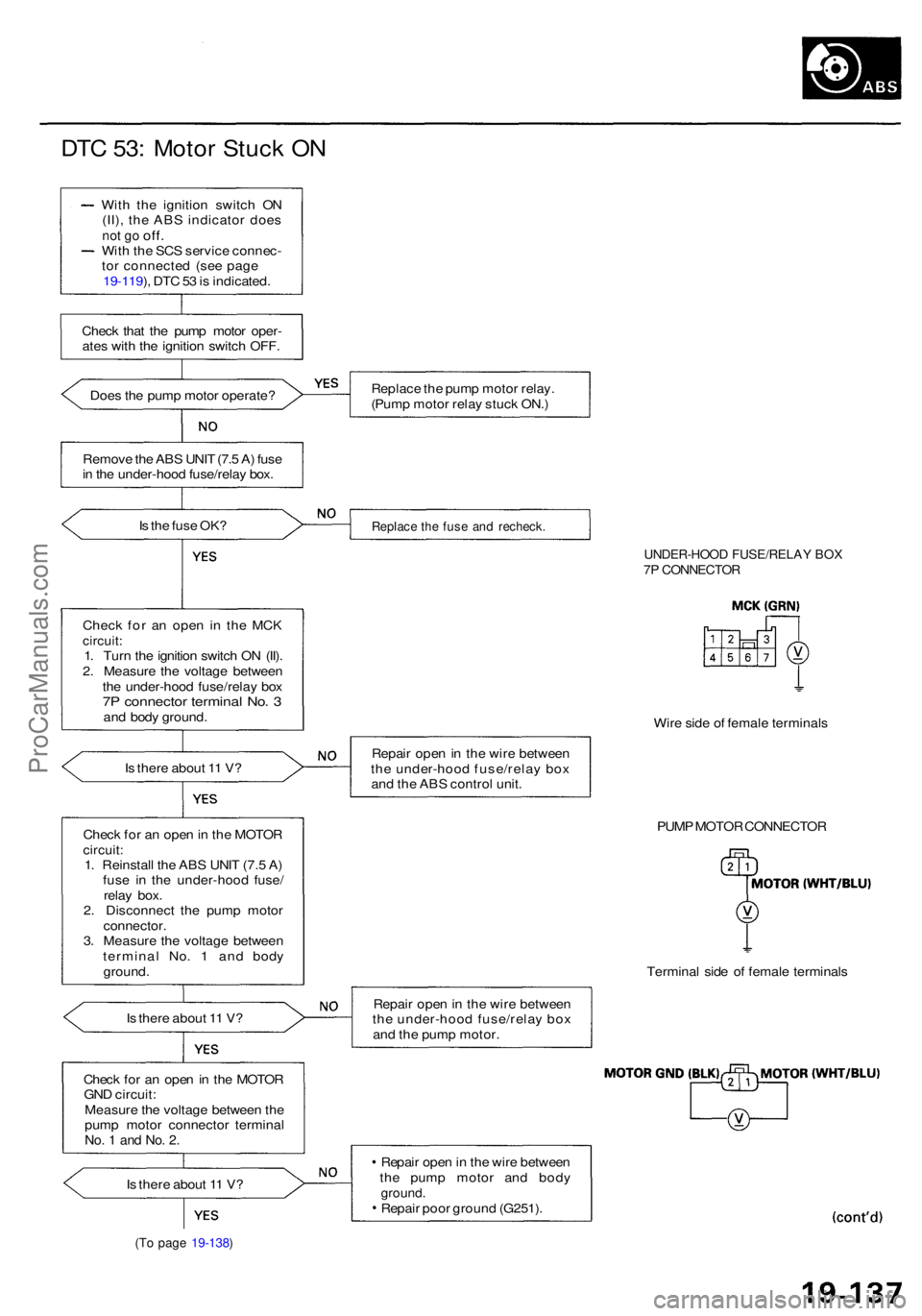
DTC 53 : Moto r Stuc k O N
Wit h th e ignitio n switc h O N
(II) , th e AB S indicato r doe s
not g o off .Wit h th e SC S servic e connec -
to r connecte d (se e pag e
19-119 ), DT C 53 is indicated .
Chec k tha t th e pum p moto r oper -
ate s wit h th e ignitio n switc h OFF .
Doe s th e pum p moto r operate ?
Remov e th e AB S UNI T (7. 5 A ) fus e
i n th e under-hoo d fuse/rela y box .
I s th e fus e OK ?
Chec k fo r a n ope n i n th e MC K
circuit :1. Tur n th e ignitio n switc h O N (II) .
2 . Measur e th e voltag e betwee n
th e under-hoo d fuse/rela y bo x
7P connecto r termina l No . 3an d bod y ground .
I s ther e abou t 1 1 V ?
Chec k fo r a n ope n in th e MOTO R
circuit:1. Reinstal l th e AB S UNI T (7. 5 A )
fus e i n th e under-hoo d fuse /
rela y box .
2 . Disconnec t th e pum p moto r
connector .3. Measur e th e voltag e betwee n
termina l No . 1 an d bod y
ground .
I s ther e abou t 1 1 V ?
Chec k fo r a n ope n in th e MOTO R
GN D circuit :
Measur e th e voltag e betwee n th e
pum p moto r connecto r termina l
No. 1 an d No . 2 .
Is ther e abou t 1 1 V ?
(To pag e 19-138 )
Replac e th e pum p moto r relay .
(Pum p moto r rela y stuc k ON. )
Replac e th e fus e an d recheck .
UNDER-HOO D FUSE/RELA Y BO X7P CONNECTO R
Wire sid e o f femal e terminal s
Repai r ope n in th e wir e betwee n
th e under-hoo d fuse/rela y bo x
an d th e AB S contro l unit .
PUMP MOTO R CONNECTO R
Termina l sid e o f femal e terminal s
Repai r ope n in th e wir e betwee n
th e under-hoo d fuse/rela y bo x
an d th e pum p motor .
Repai r ope n in th e wir e betwee n
th e pum p moto r an d bod y
ground .Repair poo r groun d (G251) .
ProCarManuals.com
Page 1182 of 1954
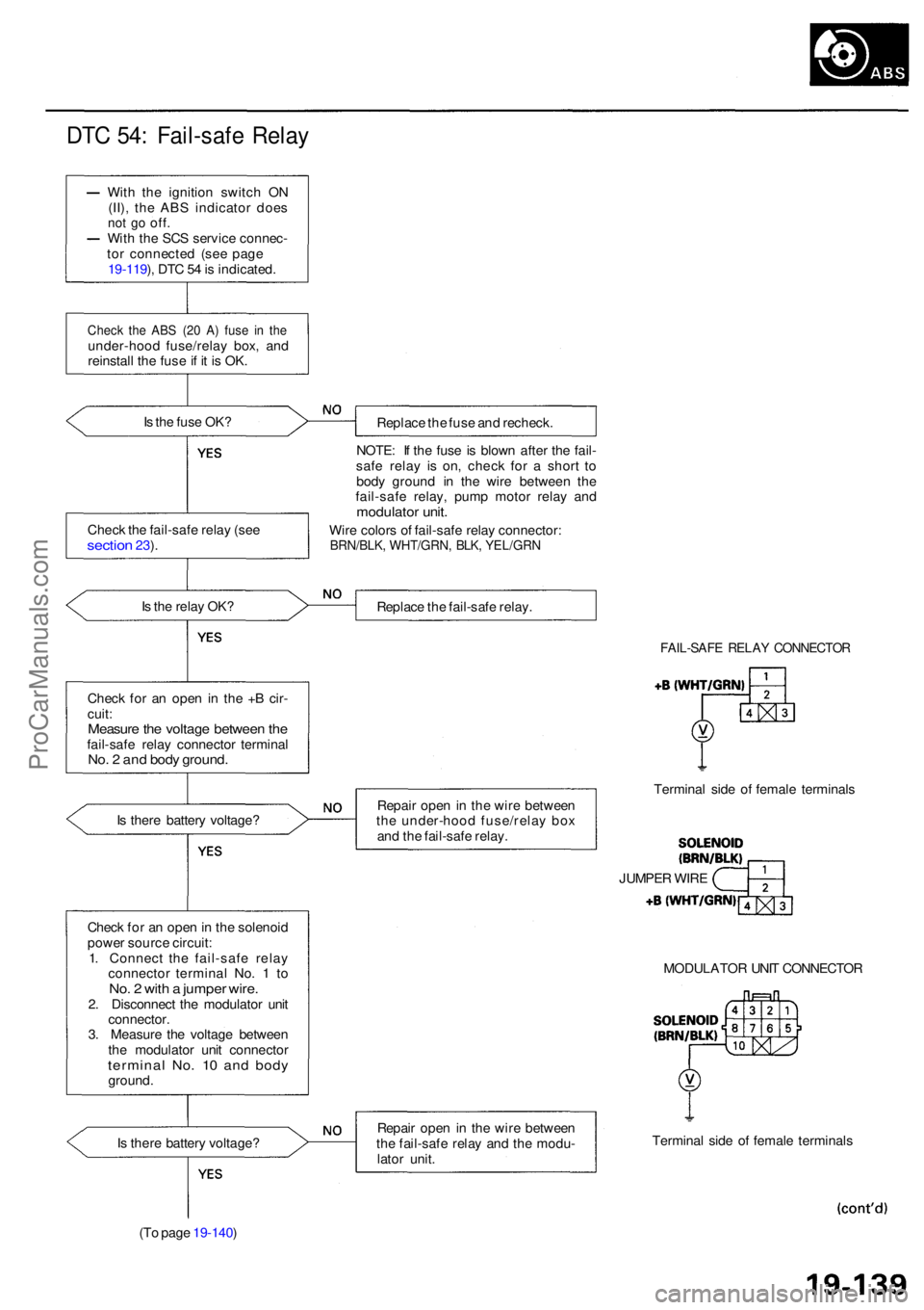
DTC 54 : Fail-saf e Rela y
With th e ignitio n switc h O N
(II) , th e AB S indicato r doe s
not g o off .With th e SC S servic e connec -
to r connecte d (se e pag e
19-119 ), DT C 5 4 is indicated .
Check th e AB S (2 0 A ) fus e i n th eunder-hoo d fuse/rela y box , an d
reinstal l th e fus e if i t i s OK .
I s th e fus e OK ?
Replace th e fus e an d recheck .
NOTE : I f th e fus e i s blow n afte r th e fail -
saf e rela y i s on , chec k fo r a shor t t o
bod y groun d i n th e wir e betwee n th e
fail-saf e relay , pum p moto r rela y an d
modulato r unit .
Wire color s o f fail-saf e rela y connector :BRN/BLK, WHT/GRN , BLK , YEL/GR N
Is th e rela y OK ?
Replace th e fail-saf e relay .
Chec k fo r a n ope n in th e + B cir -
cuit :
Measur e th e voltag e betwee n th efail-saf e rela y connecto r termina lNo. 2 an d bod y ground .
FAIL-SAF E RELA Y CONNECTO R
Is ther e batter y voltage ? Repai
r ope n in th e wir e betwee n
th e under-hoo d fuse/rela y bo x
an d th e fail-saf e relay . Termina
l sid e o f femal e terminal s
Chec k fo r a n ope n in th e solenoi d
powe r sourc e circuit :
1 . Connec t th e fail-saf e rela y
connecto r termina l No . 1 to
No . 2 wit h a jumpe r wire .2. Disconnec t th e modulato r uni t
connector .
3 . Measur e th e voltag e betwee n
th e modulato r uni t connecto r
terminal No . 1 0 an d bod yground . MODULATO
R UNI T CONNECTO R
I s ther e batter y voltage ?
(T o pag e 19-140 ) Repai
r ope n in th e wir e betwee n
th e fail-saf e rela y an d th e modu -
lato r unit . Termina
l sid e o f femal e terminal s
JUMPE
R WIR E
Chec
k th e fail-saf e rela y (se e
sectio n 23).
ProCarManuals.com
Page 1183 of 1954
Troubleshooting
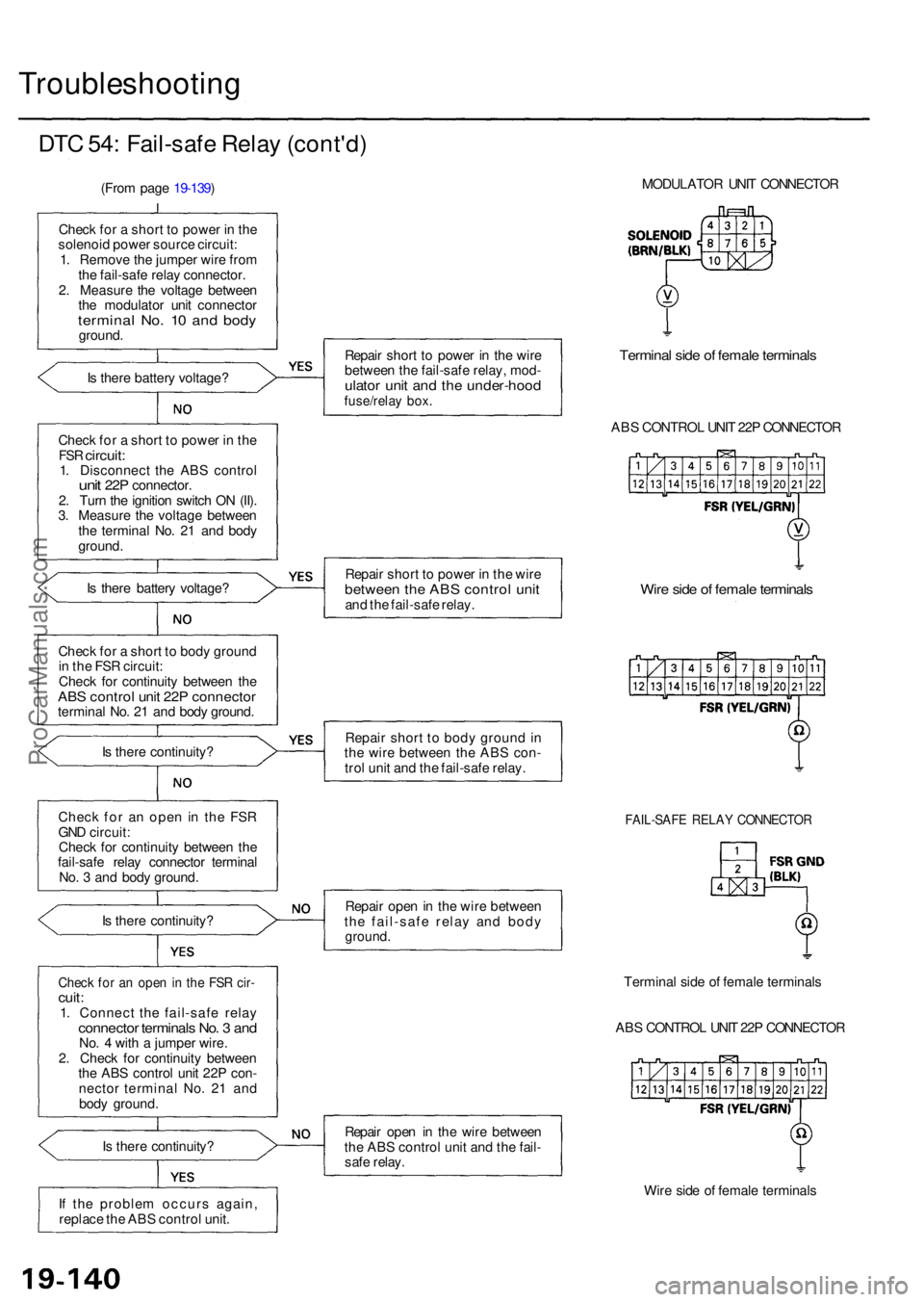
DTC 54 : Fail-saf e Rela y (cont'd )
(From pag e 19-139 )
Chec k fo r a shor t t o powe r i n th e
solenoi d powe r sourc e circuit :
1 . Remov e th e jumpe r wir e fro m
th e fail-safe relay connector .
2 . Measur e th e voltag e betwee n
th e modulato r uni t connecto r
terminal No . 1 0 an d bod yground .
I s ther e batter y voltage ?
Chec k fo r a shor t t o powe r i n th e
FS R circuit :1. Disconnec t th e AB S contro lunit 22 P connector .
2 . Tur n th e ignitio n switc h O N (II) .
3 . Measur e th e voltag e betwee n
th e termina l No . 2 1 an d bod y
ground .
I s ther e batter y voltage ?
Chec k fo r a shor t t o bod y groun d
i n th e FS R circuit :
Chec k fo r continuit y betwee n th e
AB S contro l uni t 22 P connecto rterminal No . 2 1 an d bod y ground .
I s ther e continuity ?
Chec k fo r a n ope n i n the FSR
GN D circuit :
Chec k fo r continuit y betwee n th e
fail-saf e rela y connecto r termina l
No . 3 an d bod y ground .
I s ther e continuity ?
Check fo r a n ope n in th e FS R cir -cuit :1. Connec t th e fail-saf e rela yconnecto r terminal s No . 3 an dNo. 4 wit h a jumpe r wire .
2 . Chec k fo r continuit y betwee n
th e AB S contro l uni t 22 P con -
necto r termina l No . 2 1 an d
bod y ground .
I s ther e continuity ?
I f th e proble m occur s again ,
replac e th e AB S contro l unit . Repai
r shor t t o powe r i n th e wir e
betwee n th e fail-saf e relay , mod -
ulator uni t an d th e under-hoo dfuse/relay box .
Termina l sid e o f femal e terminal s
ABS CONTRO L UNI T 22 P CONNECTO R
Repai r shor t t o powe r i n th e wir e
betwee n th e AB S contro l uni tand th e fail-saf e relay .Wire sid e o f femal e terminal s
Repair shor t t o bod y groun d in
th e wir e betwee n th e AB S con -
tro l uni t an d th e fail-saf e relay .
FAIL-SAF E RELA Y CONNECTO R
Repair ope n in th e wir e betwee n
th e fail-saf e rela y an d bod y
ground .
Termina l sid e o f femal e terminal s
AB S CONTRO L UNI T 22 P CONNECTO R
Repai r ope n i n th e wir e betwee n
th e AB S contro l uni t an d th e fail -
saf e relay .
Wire sid e o f femal e terminal s
MODULATO
R UNI T CONNECTO R
ProCarManuals.com
Page 1190 of 1954
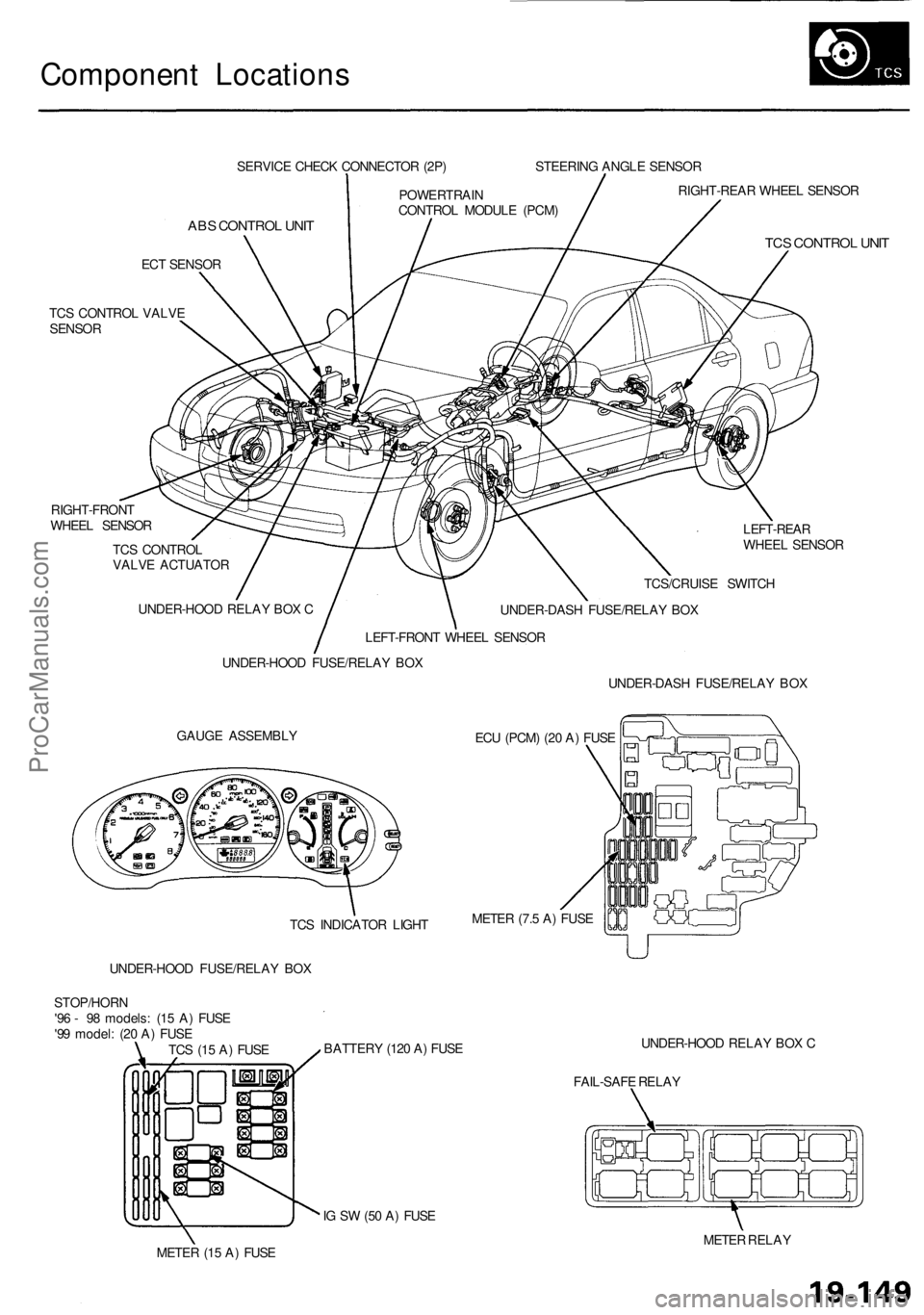
Component Locations
SERVICE CHECK CONNECTOR (2P)
ABS CONTROL UNIT
ECT SENSOR
TCS CONTROL VALVE
SENSOR
RIGHT-FRONT
WHEEL SENSOR
TCS CONTROL
VALVE ACTUATOR
LEFT-REAR
WHEEL SENSOR
GAUGE ASSEMBLY
ECU (PCM) (20 A) FUSE
UNDER-HOOD FUSE/RELAY BOX
BATTERY (120 A) FUSE
UNDER-HOOD RELAY BOX C
FAIL-SAFE RELAY
IG SW (50 A) FUSE
METER (15 A) FUSE
METER RELAY
TCS (15 A) FUSE
STOP/HORN
'96 - 98 models: (15 A) FUSE
'99 model: (20 A) FUSE
UNDER-HOOD FUSE/RELAY BOX
UNDER-HOOD RELAY BOX C
LEFT-FRONT WHEEL SENSOR
POWERTRAIN
CONTROL MODULE (PCM)
STEERING ANGLE SENSOR
RIGHT-REAR WHEEL SENSOR
TCS CONTROL UNIT
TCS/CRUISE SWITCH
UNDER-DASH FUSE/RELAY BOX
UNDER-DASH FUSE/RELAY BOX
METER (7.5 A) FUSE
TCS INDICATOR LIGHTProCarManuals.com
Page 1201 of 1954
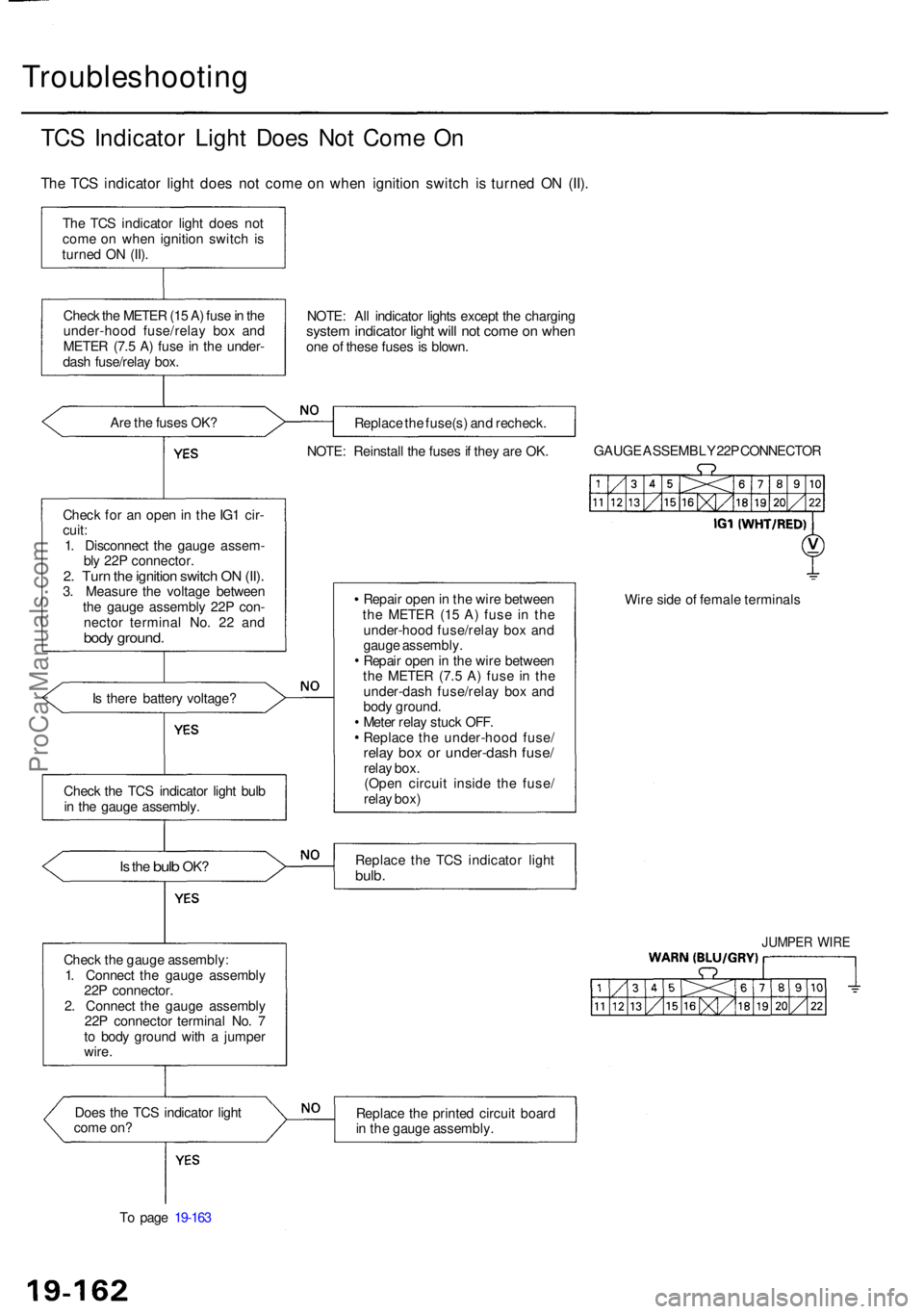
Troubleshooting
TCS Indicato r Ligh t Doe s No t Com e O n
Th e TC S indicato r ligh t doe s no t com e o n whe n ignitio n switc h i s turne d O N (II) .
The TC S indicato r ligh t doe s no t
com e o n whe n ignitio n switc h is
turne d O N (II) .
Chec k th e METE R (1 5 A ) fus e in th e
under-hoo d fuse/rela y bo x an d
METE R (7. 5 A ) fus e i n th e under -
das h fuse/rela y box .
Ar e th e fuse s OK ?
Chec k fo r a n ope n in th e IG 1 cir -
cuit :
1 . Disconnec t th e gaug e assem -
bl y 22 P connector .
2. Tur n th e ignitio n switc h O N (II) .3. Measur e th e voltag e betwee n
th e gaug e assembl y 22 P con -
necto r termina l No . 2 2 an d
body ground .
Is ther e batter y voltage ?
Is th e bul b OK ?
Chec k th e gaug e assembly :
1 . Connec t th e gaug e assembl y
22 P connector .
2 . Connec t th e gaug e assembl y
22 P connecto r termina l No . 7
t o bod y groun d wit h a jumpe r
wire .
Doe s th e TC S indicato r ligh t
com e on ?
T o pag e 19-16 3 NOTE
: Al l indicato r light s excep t th e chargin g
system indicato r ligh t wil l no t com e o n whe none o f thes e fuse s i s blown .
Replac e th e fuse(s ) an d recheck .
NOTE : Reinstal l th e fuse s if the y ar e OK . GAUG
E ASSEMBL Y 22 P CONNECTO R
Repai r ope n in th e wir e betwee n
th e METE R (1 5 A ) fus e i n th e
under-hoo d fuse/rela y bo x an d
gaug e assembly .
Repai r ope n in th e wir e betwee n
th e METE R (7. 5 A ) fus e i n th e
under-das h fuse/rela y bo x an d
bod y ground .
Mete r rela y stuc k OFF .
Replac e th e under-hoo d fuse /
relay bo x o r under-das h fuse /relay box .
(Ope n circui t insid e th e fuse /
rela y box ) Wir
e sid e o f femal e terminal s
Replac e th e TC S indicato r ligh t
bulb.
JUMPE R WIR E
Replac e th e printe d circui t boar d
i n th e gaug e assembly .
Chec
k th e TC S indicato r ligh t bul b
i n th e gaug e assembly .
ProCarManuals.com
Page 1226 of 1954
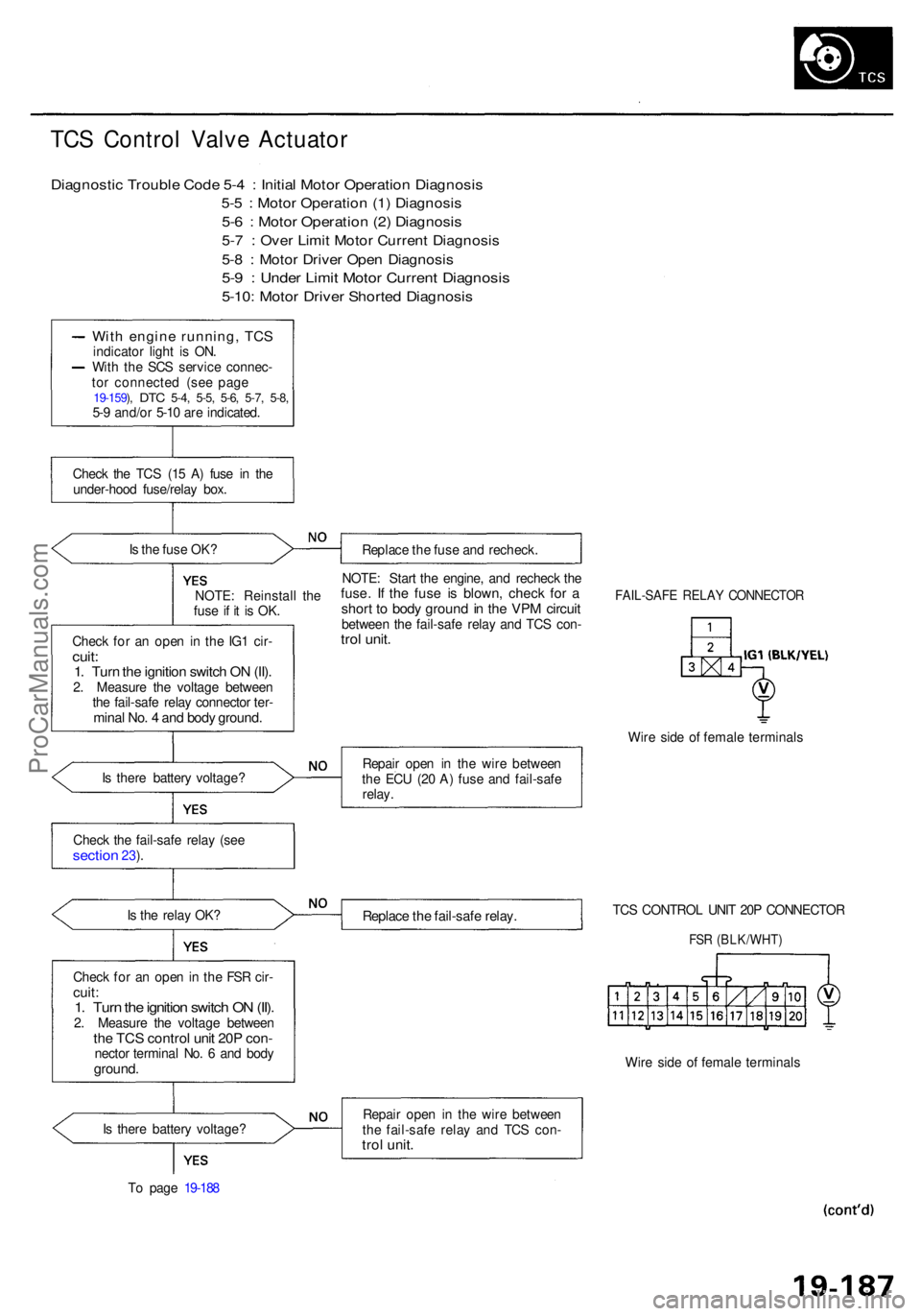
TCS Contro l Valv e Actuato r
Diagnosti c Troubl e Cod e 5- 4 : Initia l Moto r Operatio n Diagnosi s
5-5 : Moto r Operatio n (1 ) Diagnosi s
5-6 : Moto r Operatio n (2 ) Diagnosi s
5-7 : Ove r Limi t Moto r Curren t Diagnosi s
5-8 : Moto r Drive r Ope n Diagnosi s
5-9 : Unde r Limi t Moto r Curren t Diagnosi s
5-10: Moto r Drive r Shorte d Diagnosi s
With engin e running , TC Sindicato r ligh t i s ON .
Wit h th e SC S servic e connec -
to r connecte d (se e pag e
19-159 ), DT C 5-4 , 5-5 , 5-6 , 5-7 , 5-8 ,5-9 and/o r 5-1 0 ar e indicated .
Chec k th e TC S (1 5 A ) fus e i n th e
under-hoo d fuse/rela y box .
I s th e fus e OK ?
Replace th e fus e an d recheck .
NOTE : Reinstal l th e
fus e i f i t i s OK .
Chec k fo r a n ope n i n th e IG 1 cir -
cuit:1. Tur n th e ignitio n switc h O N (II) .2. Measur e th e voltag e betwee n
th e fail-saf e rela y connecto r ter -
mina l No . 4 an d bod y ground .
NOTE: Star t th e engine , an d rechec k th efuse . I f th e fus e i s blown , chec k fo r ashor t t o bod y groun d in th e VP M circui tbetwee n th e fail-saf e rela y an d TC S con -trol unit .
FAIL-SAF E RELA Y CONNECTO R
Wire sid e o f femal e terminal s
I s ther e batter y voltage ? Repai
r ope n i n th e wir e betwee n
th e EC U (2 0 A ) fus e an d fail-saf e
relay .
Chec k th e fail-saf e rela y (se e
sectio n 23).
I s th e rela y OK ?
Replac e th e fail-saf e relay .TCS CONTRO L UNI T 20 P CONNECTO R
FSR (BLK/WHT )
Check fo r a n ope n in th e FS R cir -cuit :1. Tur n th e ignitio n switc h O N (II) .2. Measur e th e voltag e betwee nthe TC S contro l uni t 20 P con -necto r termina l No . 6 an d bod yground .Wire sid e o f femal e terminal s
I s ther e batter y voltage ?
T o pag e 19-18 8 Repai
r ope n i n th e wir e betwee n
th e fail-saf e rela y an d TC S con -
trol unit .
ProCarManuals.com
Page 1234 of 1954

Component Locations
SERVICE CHECK CONNECTOR (2P)
RIGHT-REAR WHEEL SENSOR
VSA CONVERTER UNIT
VSA MODULATOR
CONTROL UNIT
TCS CONTROL
VALVE SENSOR
RIGHT-FRONT
WHEEL SENSOR
PRECHARGE
PUMP MOTOR
STEERING
ANGLE SENSOR
YAW RATE/LATERAL
ACCELERATION SENSOR
TCS CONTROL VALVE
ACTUATOR
UNDER-HOOD
RELAY BOX C
UNDER-HOOD
FUSE/RELAY BOX
VSA OFF SWITCH
UNDER-DASH FUSE/RELAY BOX
LEFT-FRONT WHEEL SENSOR
LEFT-REAR
WHEEL SENSOR
GAUGE ASSEMBLY
ABS INDICATOR
VSA SYSTEM INDICATOR
UNDER-HOOD FUSE/RELAY BOX
STOP/HORN
(20 A) FUSE
BRAKE SYSTEM INDICATOR
VSA ACTIVATION INDICATOR
UNDER-DASH FUSE/RELAY BOX
TCS
(15 A) FUSE
VSA
(20 A) FUSE
METER
(15 A) FUSE
ECU
(20 A) FUSE
METER
(7.5 A) FUSE
BATTERY
(120 A) FUSE
VSA MOTOR (40 A) FUSE
IG SW (50 A) FUSE
UNDER-HOOD RELAY BOX C
FAIL-SAFE RELAY
GAUGE RELAY
PCM
R/C MIRROR
(7.5 A) FUSEProCarManuals.com
Page 1246 of 1954
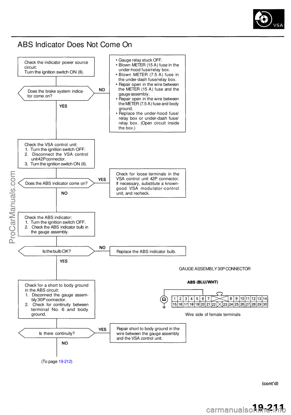
ABS Indicato r Doe s No t Com e O n
Chec k th e indicato r powe r sourc e
circuit :
Turn th e ignitio n switc h O N (II) .
Doe s th e brak e syste m indica -
to r com e on ?
Chec k th e VS A contro l unit :
1. Tur n th e ignitio n switc h OFF .2. Disconnec t th e VS A contro lunit 42 P connector .3. Tur n th e ignitio n switc h O N (II) .
Doe s th e AB S indicato r com e on ?
Chec k th e AB S indicator :
1. Tur n th e ignitio n switc h OFF .2. Chec k th e AB S indicato r bul b in
th e gaug e assembly .
Is th e bul b OK ?
Chec k fo r a shor t t o bod y groun d
i n th e AB S circuit :
1 . Disconnec t th e gaug e assem -
bly 30 P connector .2. Chec k fo r continuit y betwee nterminal No . 6 an d bod yground .
Is ther e continuity ?
(T o pag e 19-212 ) Gaug
e rela y stuc k OFF .
Blow n METE R (1 5 A ) fus e in th e
under-hoo d fuse/rela y box .
Blow n METE R (7. 5 A ) fus e i n
th e under-das h fuse/rela y box .
Repai r ope n in th e wir e betwee n
th e METE R (1 5 A ) fus e an d th e
gaug e assembly .
Repai r ope n in th e wir e betwee n
th e METE R (7. 5 A ) fus e an d bod y
ground .Replac e th e under-hoo d fuse /relay bo x o r under-das h fuse /relay box . (Ope n circui t insid ethe box. )
Check fo r loos e terminal s i n th e
VS A contro l uni t 42 P connector .
I f necessary , substitut e a known -
goo d VS A modulator-contro l
unit , an d recheck .
Replac e th e AB S indicato r bulb .
GAUG E ASSEMBL Y 30 P CONNECTO R
Wir e sid e o f femal e terminal s
Repai r shor t t o bod y groun d in th e
wir e betwee n th e gaug e assembl y
an d th e VS A contro l unit .
ProCarManuals.com
Page 1248 of 1954
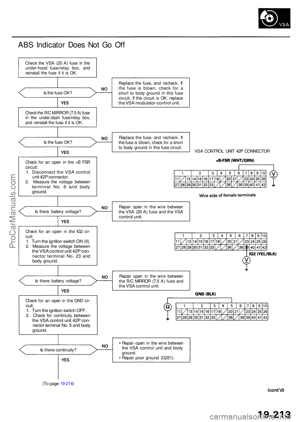
ABS Indicato r Doe s No t G o Of f
Chec k th e VS A (2 0 A ) fus e i n th e
under-hoo d fuse/rela y box , an d
reinstal l th e fus e i f i t i s OK .
I s th e fus e OK ?
Chec k th e R/ C MIRRO R (7. 5 A ) fus e
i n th e under-das h fuse/rela y box ,
an d reinstal l th e fus e if i t i s OK .
I s th e fus e OK ?
Chec k fo r a n ope n in th e + B FS R
circuit :1. Disconnec t th e VS A contro lunit 42 P connector .2. Measur e th e voltag e betwee ntermina l No . 6 an d bod yground .
Is ther e batter y voltage ?
I s ther e batter y voltage ?
Chec k fo r a n ope n in th e GN D cir -
cuit :1. Tur n th e ignitio n switc h OFF .2. Chec k fo r continuit y betwee nthe VS A contro l uni t 42 P con -necto r termina l No . 5 an d bod yground .
Is ther e continuity ?
(To pag e 19-214 ) Replac
e th e fuse , an d recheck . I f
th e fus e i s blown , chec k fo r a
shor t t o bod y groun d in thi s fus e
circuit . I f th e circui t i s OK , replac e
the VS A modulator-contro l unit .
Replac e th e fuse , an d recheck . I f
th e fus e is blown , chec k fo r a shor t
t o bod y groun d in thi s fus e circuit .
VSA CONTRO L UNI T 42 P CONNECTO R
Repai r ope n i n th e wir e betwee n
th e VS A (2 0 A ) fus e an d th e VS A
contro l unit .
Repai r ope n i n th e wir e betwee n
th e R/ C MIRRO R (7. 5 A ) fus e an d
the VS A contro l unit .
Repai r ope n in th e wir e betwee nthe VS A contro l uni t an d bod yground .
Repai r poo r groun d (G251) .
Chec
k fo r a n ope n i n th e IG 2 cir -
cuit :
1. Tur n th e ignitio n switc h O N (II) .2. Measur e th e voltag e betwee nthe VS A contro l uni t 42 P con -necto r termina l No . 2 3 an d
bod y ground .
ProCarManuals.com