wheel ACURA RL KA9 1996 Service Manual Online
[x] Cancel search | Manufacturer: ACURA, Model Year: 1996, Model line: RL KA9, Model: ACURA RL KA9 1996Pages: 1954, PDF Size: 61.44 MB
Page 1193 of 1954
System Descriptio n
Fail-Safe Functio n
I f th e contro l uni t detect s a n abnormality , i t shut s th e
tractio n contro l syste m of f an d cause s th e TC S indicato r
light t o com e on . Howeve r i f th e abnormalit y is detecte d
while th e TC S is activated , th e contro l uni t firs t estab -
lishe s th e appropriat e whee l spi n velocity , the n shut s
the syste m down , thu s preventin g excessiv e whee l spin .
Self-Diagnosi s Functio n
If th e contro l uni t detect s a n abnormality , i t record s a
Diagnosti c Troubl e Cod e (DTC ) whic h ca n b e use d t o
diagnos e th e problem . Th e DT C is show n a t th e TC S
indicato r ligh t whe n th e Servic e Chec k connecto r termi -
nal s ar e connecte d wit h th e SC S servic e connector .
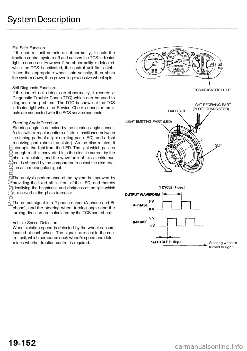
Steerin g Angl e Detectio n
Steerin g angl e is detecte d b y th e steerin g angl e sensor .
A dis c wit h a regula r patter n o f slit s is positione d betwee n
th e facin g part s o f a ligh t emittin g par t (LED) , an d a ligh t
receivin g par t (phot o transistor) . As the dis c rotates , i t
interrupt s th e ligh t fro m th e LED . Th e ligh t whic h passe s
throug h a sli t i s converte d int o th e electri c curren t b y th e
phot o transistor , an d th e wavefor m o f thi s electri c cur -
ren t i s shape d b y th e comparato r t o outpu t th e dis c rota -
tio n a s a rectangula r signal .
Th e analysi s performanc e o f th e syste m is improve d b y
providin g th e fixe d sli t i n fron t o f th e LED , an d thereb y
identifyin g th e brightnes s an d darknes s o f th e ligh t whic h
i s receive d a t th e phot o transistor .
Th e outpu t signa l i s a 2-phas e outpu t (A-phas e an d Bi -
phase) , an d th e steerin g whee l turnin g angl e an d th e
turnin g directio n ar e calculate d b y th e TC S contro l unit .
Vehicl e Spee d Detectio n
Whee l rotatio n spee d i s detecte d b y th e whee l sensors ,
locate d a t eac h wheel . Th e signal s ar e sen t t o th e con -
trol unit , whic h compare s eac h wheel' s spee d an d deter -
mines whethe r tractio n contro l i s required .
FIXED SLI T
LIGH T EMITTIN G PAR T (LED )
TCS INDICATO R LIGH T
LIGHT RECEIVIN G PAR T(PHOT O TRANSISTOR )
SLIT
Steerin g whee l i s
turne d to right .
ProCarManuals.com
Page 1195 of 1954
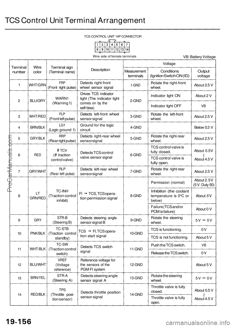
TCS Control Unit Terminal Arrangement
TCS CONTROL UNIT 14P CONNECTOR
Wire side of female terminals
VB: Battery Voltage
Terminal
number
1
2
3
4
5
6
7
8
9
10
11
12
13
14
Wire
color
WHT/GRN
BLU/GRY
WHT/RED
BRN/BLK
GRY/BLK
RED
GRY/WHT
LT
GRN/RED
GRY
PNK/BLK
WHT/BLK
BLU/WHT
BRN/YEL
RED/BLK
Terminal sign
(Terminal name)
FRP
(Front right pulse)
WARN1
(Warning 1)
FLP
(Front left pulse)
LG1
(Logic ground 1)
RRP
(Rear right pulse)
TCV
( traction
control valve)
RLP
(Rear left pulse)
TC-INH
(Traction control
inhibit)
STR-B
(Steering B)
TC-STB
(Traction control
standby)
TC-SW
(Traction control
switch)
VREF
(Voltage
reference)
STR-A
(Steering A)
TPS
(Throttle posi-
tion sensor)
Description
Detects right-front
wheel sensor signal
Drives TCS indicator
light (The indicator light
comes on by the
self-bias)
Detects left-front wheel
sensor signal
Ground for the logic
circuit
Detects right-rear wheel
sensor signal
Detects TCS control
valve sensor signal
Detects left-rear wheel
sensor signal
Fl TCS, TCS opera-
tion permission signal
Detects steering angle
sensor signal B
TCS Fl, TCS opera-
tion start signal
Detects TCS switch
signal
Reference voltage for
the sensors of the
PGM-FI system
Detects steering angle
sensor signal A
Detects throttle position
sensor signal
Voltage
Measurement
terminals
1-GND
2-GND
3-GND
4-GND
5-GND
6-GND
7-GND
8-GND
9-GND
10-GND
11-GND
12-GND
13-GND
14-GND
Conditions
(Ignition Switch ON (ID)
Rotate the right-front
wheel.
Indicator light ON
Indicator light OFF
Rotate the left-front
wheel.
Rotate the right-rear
wheel.
TCS control valve is
fully closed.
TCS control valve is
fully open.
Rotate the right-rear
wheel.
Permission (normal)
Inhibition (the coolant
temperature is 0°C or
below)
Failure (TCS and/or
PCM is failure)
Rotate the steering
wheel.
TCS is functioning.
TCS is not functioning.
Push the TCS switch.
Release the TCS switch.
Rotate the steering
wheel.
Throttle valve is fully
closed.
Throttle valve is fully
open.
Output
voltage
About 2.5 V
About 2 V
VB
About 2.5 V
Below 0.3 V
About 2.5 V
About 0.5V
About 4.5 V
About 2.5 V
About 2.5V
(5 V. Duty 50)
About 5 V
About 0 V
5V 0V
0V
About 5 V
VB
0V
About 5 V
5V 0V
About 0.5 V
About 4.5 VProCarManuals.com
Page 1197 of 1954

Troubleshooting Precautions
1. In any of these cases, the TCS indicator light may come on or stay on even the TCS system is normal.
The coolant temperature is 32°F (0°C) or below.
The parking brake is applied for more than 30 seconds while the vehicle is being driven.
The tires are not inflated to the specified pressure.
The wheel sensor signal is interrupted during driving at speeds of 6 mph (10 km/h) or above due to, for example, a
vehicle spinning.
The MAP sensor, the coolant temperature sensor, the ICM or the atmospheric pressure sensor system of the PGM-FI
system is faulty.
2. TCS does not function when the TCS indicator light is ON.
3. When both the TCS indicator light and the MIL are ON, troubleshoot the PGM-FI system first.
4. When both the TCS indicator light and the ABS indicator light are ON, troubleshoot the ABS first.
5. The DTC 4-9 (ABS down) is memorized when the ABS control unit cannot output the wheel speed signal due to, for
example, a missing or blown ABS B2 (15 A) fuse. If you fail to erase the DTC of the TCS after troubleshooting the ABS,
the DTC remains in the TCS control unit memory. Therefore, be sure to test-drive the vehicle, and check the TCS indica-
tor light before starting to troubleshoot the TCS.ProCarManuals.com
Page 1207 of 1954
Troubleshooting
Steering Angl e Senso r
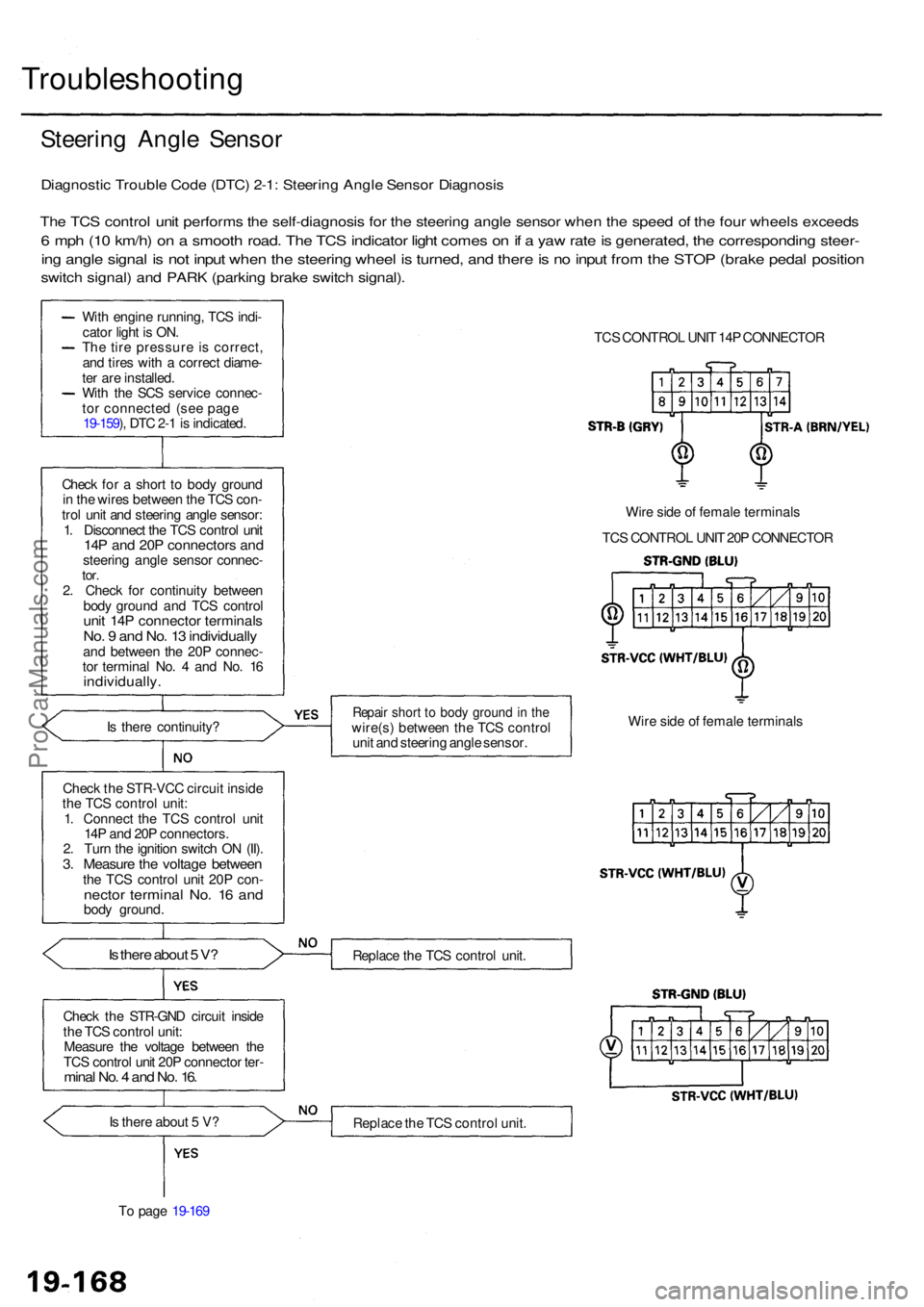
Diagnosti c Troubl e Cod e (DTC ) 2-1 : Steerin g Angl e Senso r Diagnosi s
The TC S contro l uni t perform s th e self-diagnosi s fo r th e steerin g angl e senso r whe n th e spee d o f th e fou r wheel s exceed s
6 mp h (1 0 km/h ) o n a smoot h road . Th e TC S indicato r ligh t come s o n if a ya w rat e is generated , th e correspondin g steer -
ing angl e signa l i s no t inpu t whe n th e steerin g whee l i s turned , an d ther e is n o inpu t fro m th e STO P (brak e peda l positio n
switch signal ) an d PAR K (parkin g brak e switc h signal) .
With engin e running , TC S indi -
cato r ligh t i s ON .
Th e tir e pressur e i s correct ,
an d tire s wit h a correc t diame -
te r ar e installed .
Wit h th e SC S servic e connec -
to r connecte d (se e pag e
19-159 ), DT C 2- 1 is indicated .
Chec k fo r a shor t t o bod y groun d
i n th e wire s betwee n th e TC S con -
tro l uni t an d steerin g angl e sensor :
1 . Disconnec t th e TC S contro l uni t
14P an d 20 P connector s an dsteerin g angl e senso r connec -tor.2. Chec k fo r continuit y betwee n
bod y groun d an d TC S contro l
unit 14 P connecto r terminal sNo. 9 an d No . 1 3 individuall yand betwee n th e 20 P connec -
to r termina l No . 4 an d No . 1 6
individually .
Is ther e continuity ?
Chec k th e STR-VC C circui t insid e
th e TC S contro l unit :
1 . Connec t th e TC S contro l uni t
14 P an d 20 P connectors .
2 . Tur n th e ignitio n switc h O N (II) .
3. Measur e th e voltag e betwee nthe TC S contro l uni t 20 P con -necto r termina l No . 1 6 an dbod y ground .
Is ther e abou t 5 V ?
Chec k th e STR-GN D circui t insid e
th e TC S contro l unit :
Measur e th e voltag e betwee n th e
TC S contro l uni t 20 P connecto r ter -
mina l No . 4 an d No . 16 .
Is ther e abou t 5 V ?
T o pag e 19-16 9 TC
S CONTRO L UNI T 14 P CONNECTO R
Wir e sid e o f femal e terminal s
TC S CONTRO L UNI T 20 P CONNECTO R
Repair shor t t o bod y groun d in th ewire(s ) betwee n th e TC S contro l
uni t an d steerin g angl e sensor . Wir
e sid e o f femal e terminal s
Replac e th e TC S contro l unit .
Replac e th e TC S contro l unit .
ProCarManuals.com
Page 1212 of 1954
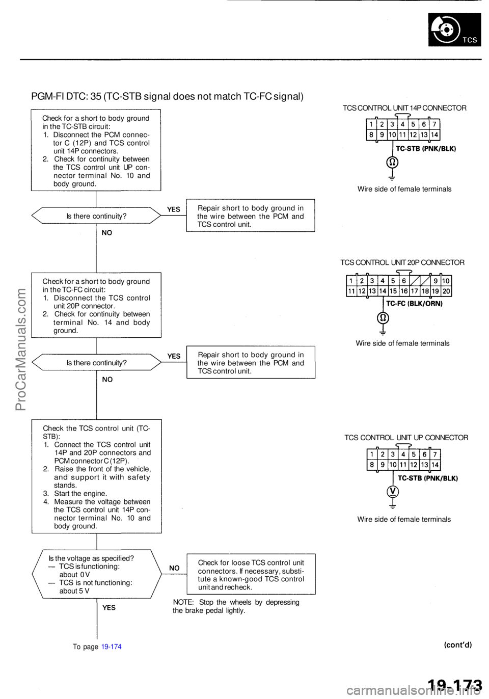
PGM-FI DTC : 3 5 (TC-ST B signa l doe s no t matc h TC-F C signal )
Check fo r a shor t t o bod y groun d
i n th e TC-ST B circuit :
1 . Disconnec t th e PC M connec -
to r C (12P ) an d TC S contro l
uni t 14 P connectors .
2 . Chec k fo r continuit y betwee n
th e TC S contro l uni t U P con -
necto r termina l No . 1 0 an d
bod y ground . TC
S CONTRO L UNI T 14 P CONNECTO R
Wir e sid e o f femal e terminal s
I s ther e continuity ? Repai
r shor t t o bod y groun d in
th e wir e betwee n th e PC M an d
TC S contro l unit .
TCS CONTRO L UNI T 20 P CONNECTO R
Chec k fo r a shor t t o bod y groun d
i n th e TC-F C circuit :
1 . Disconnec t th e TC S contro l
uni t 20 P connector .
2 . Chec k fo r continuit y betwee n
termina l No . 1 4 an d bod y
ground .
Is ther e continuity ?Repair shor t t o bod y groun d in
th e wir e betwee n th e PC M an d
TC S contro l unit . Wir
e sid e o f femal e terminal s
Chec k th e TC S contro l uni t (TC -
STB) :1. Connec t th e TC S contro l uni t
14 P an d 20 P connector s an d
PC M connecto r C (12P) .
2 . Rais e th e fron t o f th e vehicle ,
and suppor t i t wit h safet ystands.
3 . Star t th e engine .
4 . Measur e th e voltag e betwee n
th e TC S contro l uni t 14 P con -
necto r termina l No . 1 0 an d
bod y ground . TC
S CONTRO L UNI T U P CONNECTO R
Wir e sid e o f femal e terminal s
I s th e voltag e a s specified ?
TCS is functioning :about 0 V
TC S is no t functioning :
abou t 5 V Chec
k fo r loos e TC S contro l uni t
connectors . I f necessary , substi -
tut e a known-goo d TC S contro l
uni t an d recheck .
To pag e 19-17 4
NOTE : Sto p th e wheel s b y depressin g
th e brak e peda l lightly .
ProCarManuals.com
Page 1213 of 1954
Troubleshooting
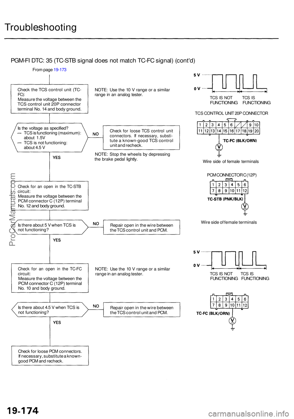
PGM-FI DTC : 3 5 (TC-ST B signa l doe s no t matc h TC-F C signal ) (cont'd )
From pag e 19-17 3
Chec k th e TC S contro l uni t (TC -
FC):Measur e th e voltag e betwee n th eTC S contro l uni t 20 P connecto rterminal No . 1 4 an d bod y ground .NOTE
: Us e th e 1 0 V rang e o r a simila r
rang e in a n analo g tester .
TCS IS NO T TC S ISFUNCTIONIN G FUNCTIONIN G
TCS CONTRO L UNI T 20 P CONNECTO R
Check fo r loos e TC S contro l uni tconnectors . I f necessary , substi -tute a known-goo d TC S contro l
uni t an d recheck .
NOTE : Sto p th e wheel s b y depressin g
th e brak e peda l lightly .
Check fo r a n ope n i n th e TC-ST Bcircuit:Measur e th e voltag e betwee n th e
PC M connecto r C (12P ) termina l
No. 1 2 an d bod y ground .
Wire sid e o f femal e terminal s
PC M CONNECTO R C (12P )
I s ther e abou t 5 V whe n TC S is
no t functioning ? Repai
r ope n in th e wir e betwee n
th e TC S contro l uni t an d PCM . Wir
e sid e o f femal e terminal s
Check fo r a n ope n i n th e TC-F Ccircuit :
Measur e th e voltag e betwee n th e
PC M connecto r C (12P ) termina lNo. 1 0 an d bod y ground . NOTE
: Us e th e 1 0 V rang e o r a simila r
rang e in a n analo g tester .
TCS IS NO T TC S ISFUNCTIONIN G FUNCTIONIN G
I s ther e abou t 4. 5 V whe n TC S is
no t functioning ? Repai
r ope n in th e wir e betwee n
th e TC S contro l uni t an d PCM .
Chec k fo r loos e PC M connectors .
I f necessary , substitut e a known -
goo d PC M an d recheck .
TC
S is functionin g (maximum) :
abou t 1.5 V
TC S is no t functioning :
abou t 4. 5 V
I
s th e voltag e a s specified ?
ProCarManuals.com
Page 1221 of 1954
Troubleshooting
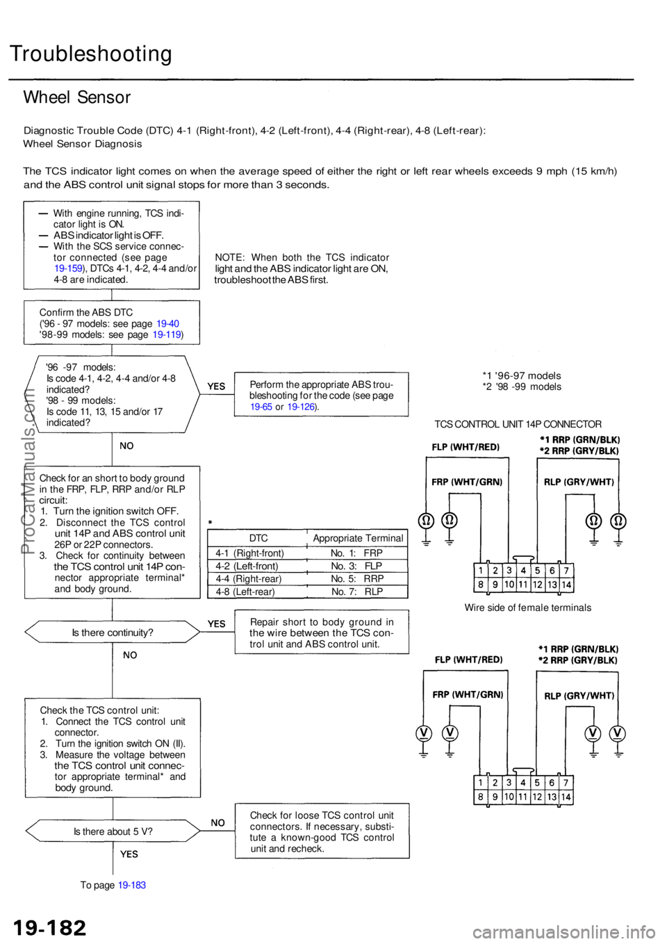
Wheel Senso r
Diagnosti c Troubl e Cod e (DTC ) 4- 1 (Right-front) , 4- 2 (Left-front) , 4- 4 (Right-rear) , 4- 8 (Left-rear) :
Wheel Senso r Diagnosi s
The TC S indicato r ligh t come s o n whe n th e averag e spee d o f eithe r th e righ t o r lef t rea r wheel s exceed s 9 mp h (1 5 km/h )
and th e AB S contro l uni t signa l stop s fo r mor e tha n 3 seconds .
With engin e running , TC S indi -
cato r ligh t i s ON .
ABS indicato r ligh t is OFF .With th e SC S servic e connec -
to r connecte d (se e pag e
19-159 ), DTC s 4-1 , 4-2 , 4- 4 and/o r
4- 8 ar e indicated . NOTE
: Whe n bot h th e TC S indicato r
light an d th e AB S indicato r ligh t ar e ON ,troubleshoo t th e AB S first .
Confir m th e AB S DT C
('9 6 - 9 7 models : se e pag e 19-4 0
'98-9 9 models : se e pag e 19-119 )
'9 6 -9 7 models :
I s cod e 4-1 , 4-2 , 4-4 and/o r 4- 8
indicated ?
'9 8 - 9 9 models :
I s cod e 11 , 13 , 1 5 and/o r 1 7
indicated ? Perfor
m th e appropriat e AB S trou -
bleshootin g fo r th e cod e (se e pag e
19-65 o r 19-126 ).
* 1 '96-9 7 model s*2 '9 8 -9 9 model s
TC S CONTRO L UNI T 14 P CONNECTO R
Chec k fo r a n shor t t o bod y groun d
i n th e FRP , FLP , RR P and/o r RL P
circuit :1. Tur n th e ignitio n switc h OFF .2. Disconnec t th e TC S contro lunit 14 P an d AB S control unit26P o r 22 P connectors .
3 . Chec k fo r continuit y betwee n
the TC S contro l uni t 14 P con -necto r appropriat e terminal *
an d bod y ground .
Is ther e continuity ?Repair shor t t o bod y groun d i nth e wir e betwee n th e TC S con -trol uni t an d AB S contro l unit . Wir
e sid e o f femal e terminal s
Chec k th e TC S contro l unit :
1 . Connec t th e TC S control unit
connector .
2 . Tur n th e ignitio n switc h O N (II) .
3 . Measur e th e voltag e betwee n
the TC S contro l uni t connec -tor appropriat e terminal * an dbody ground .
Is ther e abou t 5 V ?
T o pag e 19-18 3 Chec
k fo r loos e TC S contro l uni t
connectors . I f necessary , substi -
tut e a known-goo d TC S contro l
uni t an d recheck .
DT
C Appropriat e Termina l
4- 1 (Right-front ) No . 1 : FR P
4-2 (Left-front ) No . 3 : FL P
4-4 (Right-rear ) No . 5 : RR P
4- 8 (Left-rear ) No . 7 : RL P
ProCarManuals.com
Page 1222 of 1954
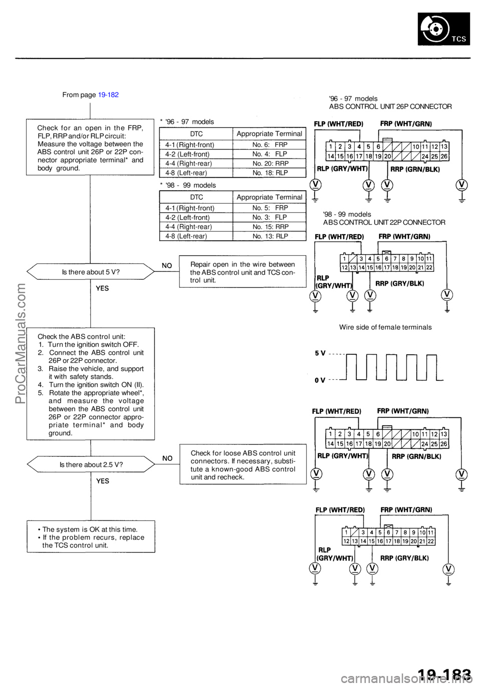
From pag e 19-18 2
Chec k fo r a n ope n i n th e FRP ,
FLP , RR P and/o r RL P circuit :
Measur e th e voltag e betwee n th e
AB S contro l uni t 26 P o r 22 P con -
necto r appropriat e terminal * an d
bod y ground .
I s ther e abou t 5 V ?
Chec k th e AB S contro l unit :
1. Tur n th e ignitio n switc h OFF .2. Connec t th e AB S contro l uni t
26 P o r 22 P connector .
3 . Rais e th e vehicle , an d suppor t
i t wit h safet y stands .
4 . Tur n th e ignitio n switc h O N (II) .
5 . Rotat e th e appropriat e wheel* ,
an d measur e th e voltag e
betwee n th e AB S contro l uni t
26 P o r 22 P connecto r appro -
priat e terminal * an d bod y
ground .
I s ther e abou t 2. 5 V ? *
'9 6 - 9 7 model s
DTC
4-1 (Right-front )
4- 2 (Left-front )
4-4 (Right-rear )
4-8 (Left-rear )
Appropriat e Termina l
No. 6 : FR P
No. 4 : FL P
No. 20 : RR P
No. 18 : RL P
* '9 8 - 9 9 model s
DTC
4-1 (Right-front )
4- 2 (Left-front )
4-4 (Right-rear )
4-8 (Left-rear )
Appropriat e Termina l
No. 5 : FR P
No. 3 : FL P
No. 15 : RR P
No. 13 : RL P
Repai r ope n in th e wir e betwee n
th e AB S contro l uni t an d TC S con -
tro l unit . '9
6 - 9 7 model s
AB S CONTRO L UNI T 26 P CONNECTO R
'9 8 - 9 9 model s
AB S CONTRO L UNI T 22 P CONNECTO R
Wir e sid e o f femal e terminal s
Chec k fo r loos e AB S contro l uni t
connectors . I f necessary , substi -
tut e a known-goo d AB S contro l
uni t an d recheck .
Th e syste m is O K a t thi s time .
I f th e proble m recurs , replac e
th e TC S contro l unit .
ProCarManuals.com
Page 1223 of 1954
Troubleshooting
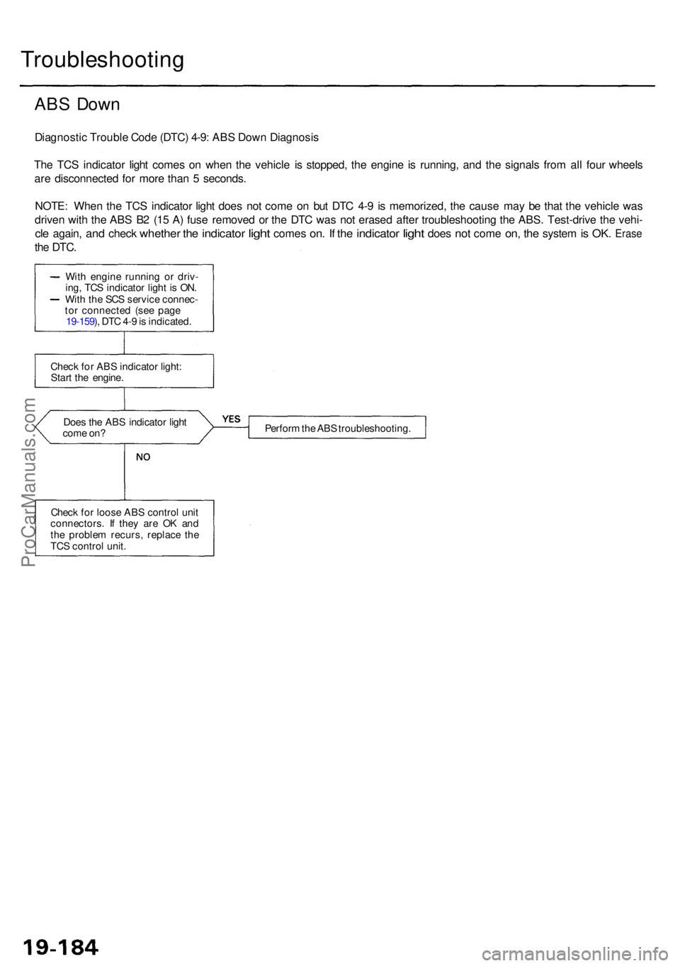
ABS Dow n
Diagnosti c Troubl e Cod e (DTC ) 4-9 : AB S Dow n Diagnosi s
Th e TC S indicato r ligh t come s o n whe n th e vehicl e i s stopped , th e engin e i s running , an d th e signal s fro m al l fou r wheel s
ar e disconnecte d fo r mor e tha n 5 seconds .
NOTE : Whe n th e TC S indicato r ligh t doe s no t com e o n bu t DT C 4- 9 i s memorized , th e caus e ma y b e tha t th e vehicl e wa s
drive n wit h th e AB S B 2 (1 5 A ) fus e remove d o r th e DT C wa s no t erase d afte r troubleshootin g th e ABS . Test-driv e th e vehi -
cle again , and chec k whethe r the indicato r light come s on. I f th e indicato r light doe s not com e on, th e syste m is OK . Eras e
the DTC .
Does th e AB S indicato r ligh t
com e on ? Perfor
m th e AB S troubleshooting .
Chec k fo r loos e AB S contro l uni t
connectors . I f the y ar e O K an d
th e proble m recurs , replac e th e
TC S contro l unit .
Chec
k fo r AB S indicato r light :
Star t th e engine .
Wit
h engin e runnin g o r driv -
ing , TC S indicato r ligh t i s ON .
Wit h th e SC S servic e connec -
to r connecte d (se e pag e
19-159 ), DT C 4- 9 is indicated .
ProCarManuals.com
Page 1234 of 1954

Component Locations
SERVICE CHECK CONNECTOR (2P)
RIGHT-REAR WHEEL SENSOR
VSA CONVERTER UNIT
VSA MODULATOR
CONTROL UNIT
TCS CONTROL
VALVE SENSOR
RIGHT-FRONT
WHEEL SENSOR
PRECHARGE
PUMP MOTOR
STEERING
ANGLE SENSOR
YAW RATE/LATERAL
ACCELERATION SENSOR
TCS CONTROL VALVE
ACTUATOR
UNDER-HOOD
RELAY BOX C
UNDER-HOOD
FUSE/RELAY BOX
VSA OFF SWITCH
UNDER-DASH FUSE/RELAY BOX
LEFT-FRONT WHEEL SENSOR
LEFT-REAR
WHEEL SENSOR
GAUGE ASSEMBLY
ABS INDICATOR
VSA SYSTEM INDICATOR
UNDER-HOOD FUSE/RELAY BOX
STOP/HORN
(20 A) FUSE
BRAKE SYSTEM INDICATOR
VSA ACTIVATION INDICATOR
UNDER-DASH FUSE/RELAY BOX
TCS
(15 A) FUSE
VSA
(20 A) FUSE
METER
(15 A) FUSE
ECU
(20 A) FUSE
METER
(7.5 A) FUSE
BATTERY
(120 A) FUSE
VSA MOTOR (40 A) FUSE
IG SW (50 A) FUSE
UNDER-HOOD RELAY BOX C
FAIL-SAFE RELAY
GAUGE RELAY
PCM
R/C MIRROR
(7.5 A) FUSEProCarManuals.com