wheel ACURA RL KA9 1996 Service Manual PDF
[x] Cancel search | Manufacturer: ACURA, Model Year: 1996, Model line: RL KA9, Model: ACURA RL KA9 1996Pages: 1954, PDF Size: 61.44 MB
Page 1157 of 1954
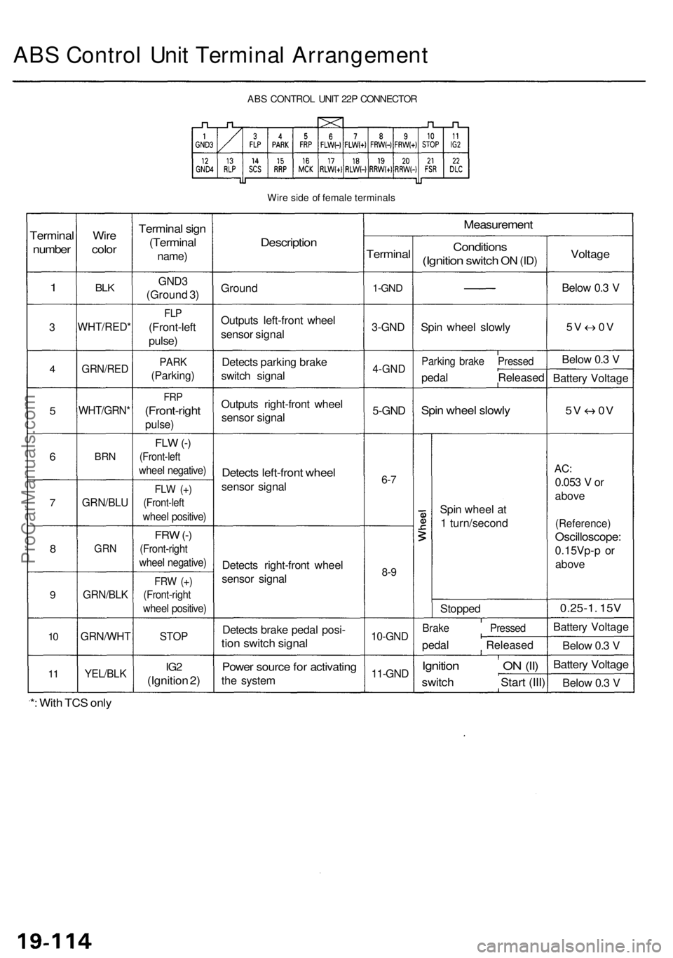
ABS Contro l Uni t Termina l Arrangemen t
ABS CONTRO L UNI T 22 P CONNECTO R
Wir e sid e o f femal e terminal s
Terminal
number
1
3
4
5
6
7
8
9
10
1 1
Wir e
colo r
BLK
WHT/RED *
GRN/RED
WHT/GRN *
BRN
GRN/BL U
GRN
GRN/BL K
GRN/WH T
YEL/BLK
Termina l sig n
(Termina l
name)
GND3
(Groun d 3 )
FL P
(Front-lef t
pulse )
PARK
(Parking )
FRP
(Front-righ t
pulse)
FLW (-)
(Front-lef t
wheel negative )
FLW (+ )
(Front-lef t
wheel positive )
FRW (-)
(Front-righ t
wheel negative )
FRW (+ )
(Front-righ t
wheel positive )
STOP
IG2
(Ignitio n 2 )
Descriptio n
Ground
Output s left-fron t whee l
senso r signa l
Detect s parkin g brak e
switc h signa l
Output s right-fron t whee l
senso r signa l
Detect s left-fron t whee l
senso r signa l
Detect s right-fron t whee l
senso r signa l
Detect s brak e peda l posi -
tion switc h signa l
Power sourc e fo r activatin g
the syste m
Measuremen t
Terminal
1-GND
3-GN D
4-GN D
5-GND
6-7
8- 9
10-GN D
11-GND
Condition s
(Ignition switch ON (ID )
Spi n whee l slowl y
Parkin g brak e Presse d
pedal Release d
Spin whee l slowl y
Spin whee l a t
1 turn/secon d
Stoppe d
Brake Presse d
pedal Release d
Ignition O N (II )
switc h Star t (III )
Voltag e
Below 0. 3 V
5 V 0 V
Below 0. 3 V
Batter y Voltag e
5V 0 V
AC:
0.05 3 V or
abov e
(Reference )
Oscilloscope :
0.15Vp-p o r
abov e
0.25-1 . 15 V
Batter y Voltag e
Belo w 0. 3 V
Batter y Voltag e
Below 0. 3 V
*: Wit h TC S onl y
ProCarManuals.com
Page 1158 of 1954
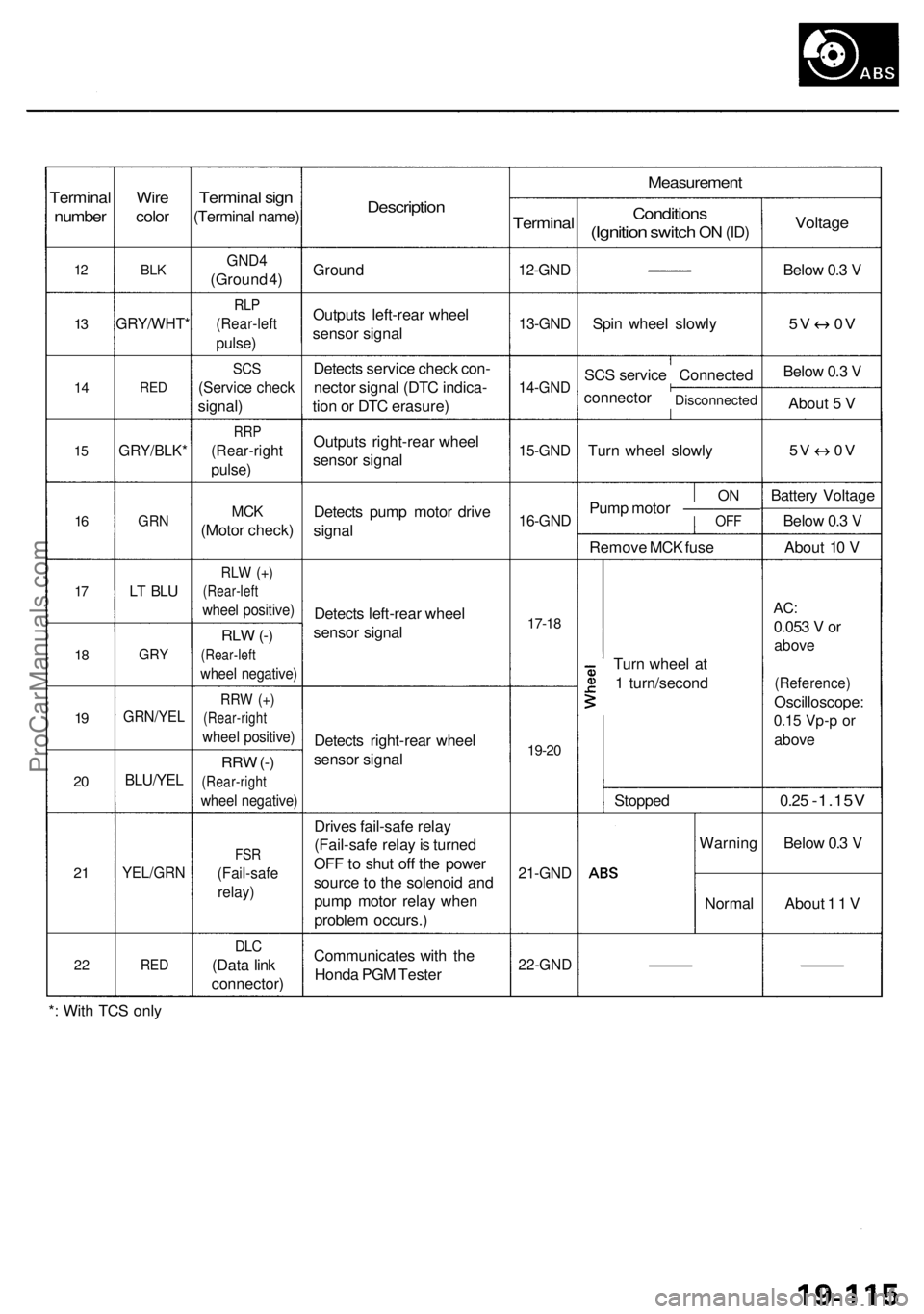
Terminal
number
12
13
1 4
15
16
17
1 8
19
2 0
2 1
2 2
Wir e
colo r
BLK
GRY/WHT *
RED
GRY/BLK *
GRN
LT BL U
GR Y
GRN/YE L
BLU/YEL
YEL/GR N
RED
Termina l sig n
(Termina l name )
GND4
(Groun d 4 )
RL P
(Rear-lef t
pulse)
SCS
(Servic e chec k
signal )
RRP
(Rear-righ t
pulse)
MCK
(Moto r check )
RLW (+ )
(Rear-lef t
wheel positive )
RLW (-)
(Rear-lef t
wheel negative )
RRW (+ )
(Rear-righ t
wheel positive )
RRW (-)
(Rear-righ t
wheel negative )
FSR
(Fail-saf e
relay)
DLC
(Dat a lin k
connector )
Description
Ground
Output s left-rea r whee l
senso r signa l
Detect s servic e chec k con -
necto r signa l (DT C indica -
tio n o r DT C erasure )
Output s right-rea r whee l
senso r signa l
Detect s pum p moto r driv e
signa l
Detect s left-rea r whee l
senso r signa l
Detect s right-rea r whee l
senso r signa l
Drive s fail-saf e rela y
(Fail-saf e rela y is turne d
OF F to shu t of f th e powe r
sourc e to th e solenoi d an d
pum p moto r rela y whe n
proble m occurs. )
Communicate s wit h th e
Hond a PG M Teste r
Measuremen t
Terminal
12-GND
13-GND
14-GN D
15-GND
16-GND
17-18
19-2 0
21-GN D
22-GN D
Condition s
(Ignition switch ON (ID )
Spi n whee l slowl y
SC S servic e Connecte d
connecto r
Disconnecte d
Turn whee l slowl y
ONPum p moto r —————OF F
Remov e MC K fus e
Tur n whee l a t
1 turn/secon d
Stoppe d
Warnin g
Norma l
Voltage
Below 0. 3 V
5 V 0 V
Below 0. 3 V
Abou t 5 V
5V 0 V
Batter y Voltag e
Belo w 0. 3 V
Abou t 1 0 V
AC :
0.05 3 V or
abov e
(Reference )
Oscilloscope :
0.15 Vp- p o r
abov e
0.25 -1.15 V
Below 0. 3 V
Abou t 1 1 V
* : Wit h TC S onl y
ProCarManuals.com
Page 1160 of 1954
Troubleshooting Precautions
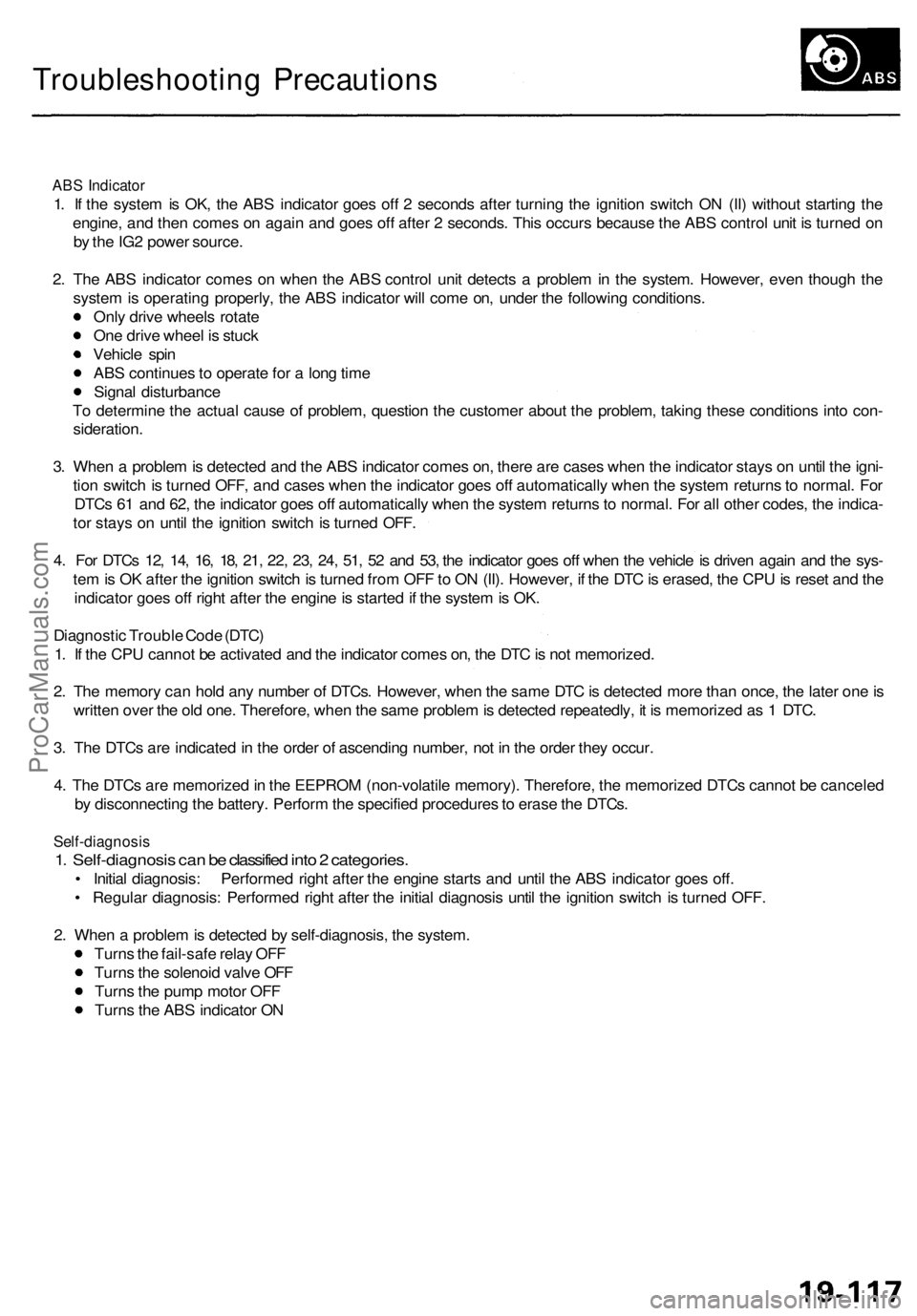
ABS Indicator
1. If the system is OK, the ABS indicator goes off 2 seconds after turning the ignition switch ON (II) without starting the
engine, and then comes on again and goes off after 2 seconds. This occurs because the ABS control unit is turned on
by the IG2 power source.
2. The ABS indicator comes on when the ABS control unit detects a problem in the system. However, even though the
system is operating properly, the ABS indicator will come on, under the following conditions.
Only drive wheels rotate
One drive wheel is stuck
Vehicle spin
ABS continues to operate for a long time
Signal disturbance
To determine the actual cause of problem, question the customer about the problem, taking these conditions into con-
sideration.
3. When a problem is detected and the ABS indicator comes on, there are cases when the indicator stays on until the igni-
tion switch is turned OFF, and cases when the indicator goes off automatically when the system returns to normal. For
DTCs 61 and 62, the indicator goes off automatically when the system returns to normal. For all other codes, the indica-
tor stays on until the ignition switch is turned OFF.
4. For DTCs 12, 14, 16, 18, 21, 22, 23, 24, 51, 52 and 53, the indicator goes off when the vehicle is driven again and the sys-
tem is OK after the ignition switch is turned from OFF to ON (II). However, if the DTC is erased, the CPU is reset and the
indicator goes off right after the engine is started if the system is OK.
Diagnostic Trouble Code (DTC)
1. If the CPU cannot be activated and the indicator comes on, the DTC is not memorized.
2. The memory can hold any number of DTCs. However, when the same DTC is detected more than once, the later one is
written over the old one. Therefore, when the same problem is detected repeatedly, it is memorized as 1 DTC.
3. The DTCs are indicated in the order of ascending number, not in the order they occur.
4. The DTCs are memorized in the EEPROM (non-volatile memory). Therefore, the memorized DTCs cannot be canceled
by disconnecting the battery. Perform the specified procedures to erase the DTCs.
Self-diagnosis
1. Self-diagnosis can be classified into 2 categories.
• Initial diagnosis: Performed right after the engine starts and until the ABS indicator goes off.
• Regular diagnosis: Performed right after the initial diagnosis until the ignition switch is turned OFF.
2. When a problem is detected by self-diagnosis, the system.
Turns the fail-safe relay OFF
Turns the solenoid valve OFF
Turns the pump motor OFF
Turns the ABS indicator ONProCarManuals.com
Page 1161 of 1954
Troubleshooting Precautions
Kickback
1. The motor operates when the ABS is functioning, and the fluid in the reservoir is forced out to the master cylinder,
causing kickback at the brake pedal.
Pump Motor
1. The pump motor operates when the ABS is functioning.
2. The ABS control unit checks the pump motor operation during initial diagnosis when the vehicle is started. You may
hear the motor operate at this time, but it is normal.
Brake Fluid Replacement/Air Bleeding
1. Brake fluid replacement and air bleeding procedures are the same as vehicles without ABS. To ease bleeding, start
with the front wheels.
Troubleshooting
1. The troubleshooting flowcharts procedures assume that the cause of the problem is still present and the ABS indicator
is still on. Following the flowchart when the ABS indicator does not come on can result in incorrect diagnosis.
2. Question the customer about the conditions when the problem occurred, and try to reproduce the same conditions
for troubleshooting.
Find out when the ABS indicator came on, such as during initial diagnosis, during ABS control, after ABS control,
when vehicle speed was at a certain speed, etc.
3. When the ABS indicator does not come on during the test-drive, but troubleshooting is performed based on the DTC,
check for loose connectors, poor contact at the terminals, etc. before you start troubleshooting.
4. After troubleshooting, erase the DTC and test-drive the vehicle. Be sure the ABS indicator does not come on.
5. The connector illustrations show the female terminals with a single outline and the male terminals with a double outline.ProCarManuals.com
Page 1170 of 1954
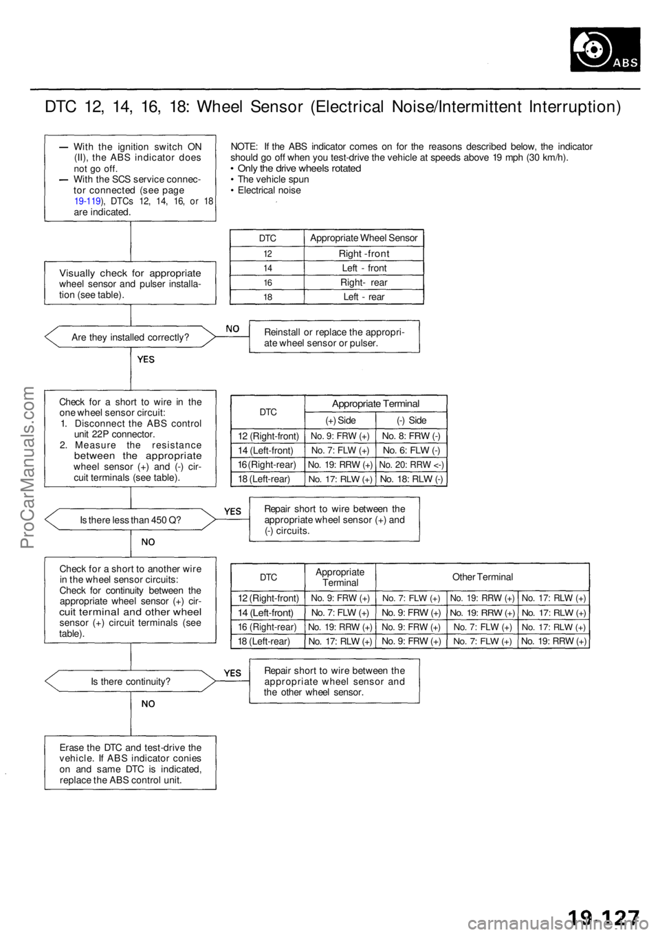
DTC 12 , 14 , 16 , 18 : Whee l Senso r (Electrica l Noise/Intermitten t Interruption )
Are the y installe d correctly ?
Chec k fo r a shor t t o wir e i n th e
on e whee l senso r circuit :
1 . Disconnec t th e AB S contro l
uni t 22 P connector .
2 . Measur e th e resistanc e
between th e appropriat ewheel senso r (+ ) an d (- ) cir -
cui t terminal s (se e table) .
I s ther e les s tha n 45 0 Q ?
Chec k fo r a shor t t o anothe r wir e
i n th e whee l senso r circuits :
Chec k fo r continuit y betwee n th e
appropriat e whee l senso r (+ ) cir -
cuit termina l an d othe r whee lsensor (+ ) circui t terminal s (se e
table) .
Is ther e continuity ? NOTE
: I f th e AB S indicato r come s o n fo r th e reason s describe d below , th e indicato r
shoul d g o of f whe n yo u test-driv e th e vehicl e a t speed s abov e 1 9 mp h (3 0 km/h) .
• Onl y th e driv e wheel s rotate d• Th e vehicl e spu n
• Electrica l nois e
DTC
12
1 4
16
18
Appropriat e Whee l Senso r
Right -fron t
Left - fron t
Right - rea r
Lef t - rea r
Reinstal l o r replac e th e appropri -
at e whee l senso r o r pulser .
DTC
12 (Right-front )
1 4 (Left-front )
1 6 (Right-rear )
1 8 (Left-rear )
Appropriat e Termina l
(+) Sid e
No. 9 : FR W (+ )
No . 7 : FL W (+ )
No . 19 : RR W (+ )
No . 17 : RL W (+ )
(-) Sid e
No. 8 : FR W (-)
No . 6 : FL W (-)
No . 20 : RR W <- )
No . 18 : RL W (-)
Repai r shor t t o wir e betwee n th e
appropriat e whee l senso r (+ ) an d
(- ) circuits .
DTC
12 (Right-front )
14 (Left-front )
16 (Right-rear )
18 (Left-rear )Appropriat
e
Termina l
No. 9 : FR W (+ )
No . 7 : FL W (+ )
No . 19 : RR W (+ )
No . 17 : RL W (+ )
Othe r Termina l
No. 7 : FL W (+ )
No . 9 : FR W (+ )
No . 9 : FR W (+ )
No . 9 : FR W (+ )
No . 19 : RR W (+ )
No . 19 : RR W (+ )
No . 7 : FL W (+ )
No . 7 : FL W (+ )
No . 17 : RL W (+ )
No . 17 : RL W (+ )
No . 17 : RL W (+ )
No . 19 : RR W (+ )
Repai r shor t t o wir e betwee n th e
appropriat e whee l senso r an d
th e othe r whee l sensor .
Wit
h th e ignitio n switc h O N
(II) , th e AB S indicato r doe s
not g o off .With th e SC S servic e connec -
to r connecte d (se e pag e
19-119 ), DTC s 12 , 14 , 16 , o r 1 8are indicated .
Visually chec k fo r appropriat ewheel senso r an d pulse r installa -
tio n (se e table) .
Eras e th e DT C an d test-driv e th e
vehicle . I f AB S indicato r conie s
o n an d sam e DT C is indicated ,
replac e th e AB S contro l unit .
ProCarManuals.com
Page 1186 of 1954
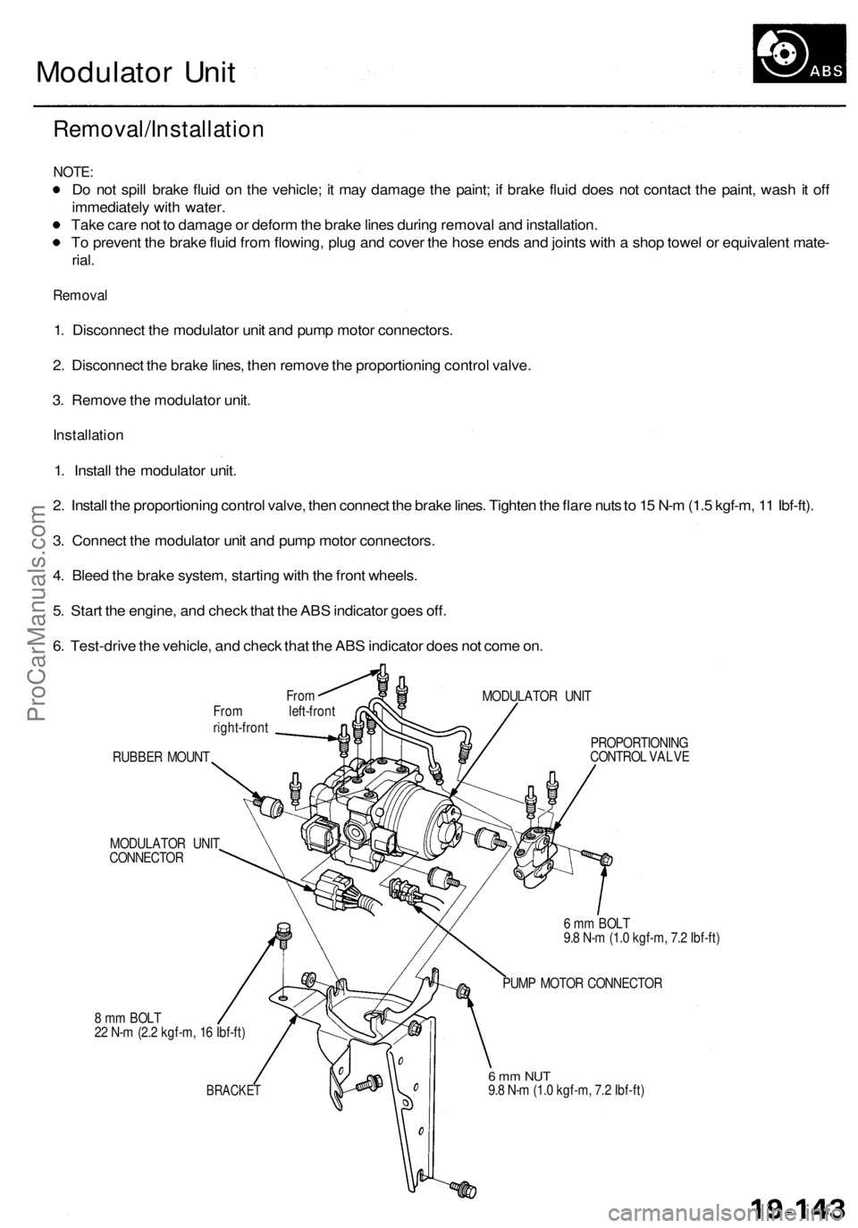
Modulator Unit
Removal/Installation
NOTE:
Do not spill brake fluid on the vehicle; it may damage the paint; if brake fluid does not contact the paint, wash it off
immediately with water.
Take care not to damage or deform the brake lines during removal and installation.
To prevent the brake fluid from flowing, plug and cover the hose ends and joints with a shop towel or equivalent mate-
rial.
Removal
1. Disconnect the modulator unit and pump motor connectors.
2. Disconnect the brake lines, then remove the proportioning control valve.
3. Remove the modulator unit.
Installation
1. Install the modulator unit.
2. Install the proportioning control valve, then connect the brake lines. Tighten the flare nuts to 15 N-m (1.5 kgf-m, 11 Ibf-ft).
3. Connect the modulator unit and pump motor connectors.
4. Bleed the brake system, starting with the front wheels.
5. Start the engine, and check that the ABS indicator goes off.
6. Test-drive the vehicle, and check that the ABS indicator does not come on.
From
From left-front
right-front
MODULATOR UNIT
RUBBER MOUNT
MODULATOR UNIT
CONNECTOR
8 mm BOLT
22 N-m (2.2 kgf-m, 16 Ibf-ft)
BRACKET
PROPORTIONING
CONTROL VALVE
6 mm BOLT
9.8 N-m (1.0 kgf-m, 7.2 Ibf-ft)
PUMP MOTOR CONNECTOR
6 mm NUT
9.8 N-m (1.0 kgf-m, 7.2 Ibf-ft)ProCarManuals.com
Page 1188 of 1954
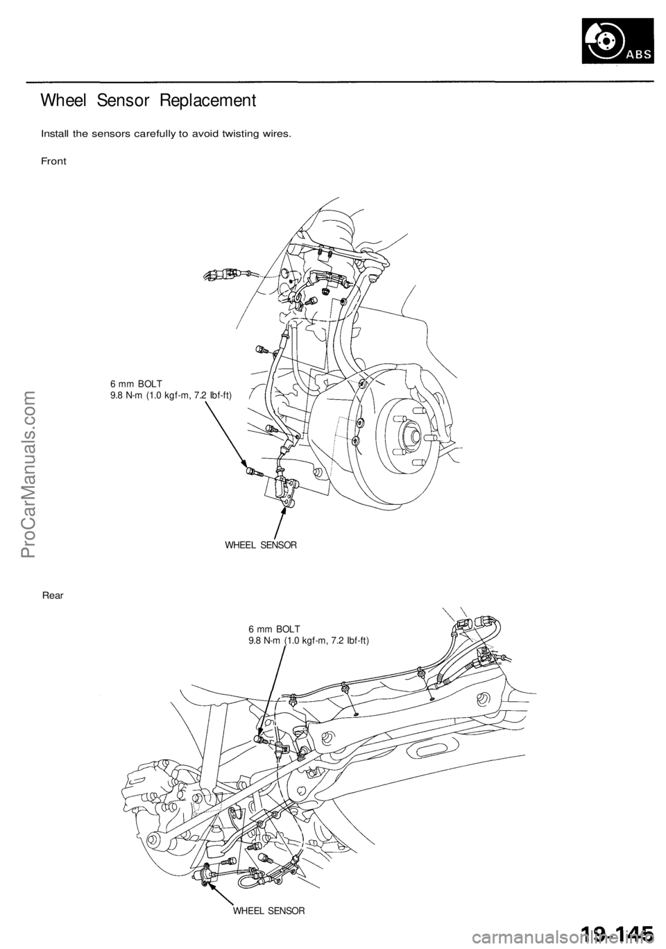
Wheel Sensor Replacement
Install the sensors carefully to avoid twisting wires.
Front
6 mm BOLT
9.8 N-m (1.0 kgf-m, 7.2 Ibf-ft)
WHEEL SENSOR
Rear
6 mm BOLT
9.8 N-m (1.0 kgf-m, 7.2 Ibf-ft)
WHEEL SENSORProCarManuals.com
Page 1190 of 1954
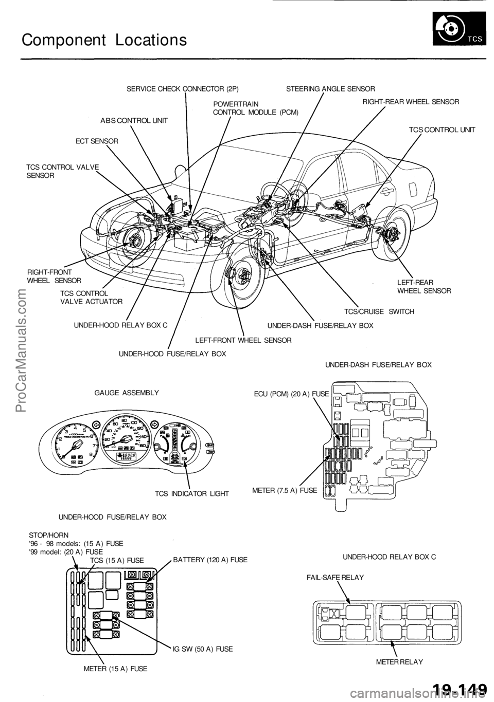
Component Locations
SERVICE CHECK CONNECTOR (2P)
ABS CONTROL UNIT
ECT SENSOR
TCS CONTROL VALVE
SENSOR
RIGHT-FRONT
WHEEL SENSOR
TCS CONTROL
VALVE ACTUATOR
LEFT-REAR
WHEEL SENSOR
GAUGE ASSEMBLY
ECU (PCM) (20 A) FUSE
UNDER-HOOD FUSE/RELAY BOX
BATTERY (120 A) FUSE
UNDER-HOOD RELAY BOX C
FAIL-SAFE RELAY
IG SW (50 A) FUSE
METER (15 A) FUSE
METER RELAY
TCS (15 A) FUSE
STOP/HORN
'96 - 98 models: (15 A) FUSE
'99 model: (20 A) FUSE
UNDER-HOOD FUSE/RELAY BOX
UNDER-HOOD RELAY BOX C
LEFT-FRONT WHEEL SENSOR
POWERTRAIN
CONTROL MODULE (PCM)
STEERING ANGLE SENSOR
RIGHT-REAR WHEEL SENSOR
TCS CONTROL UNIT
TCS/CRUISE SWITCH
UNDER-DASH FUSE/RELAY BOX
UNDER-DASH FUSE/RELAY BOX
METER (7.5 A) FUSE
TCS INDICATOR LIGHTProCarManuals.com
Page 1191 of 1954
System Description
Outline
Role of System
The traction control is a variable system designed to enhance traction during acceleration and cornering. It does so by
determining the optimum amount of wheel spin for any given driving situation, then suppressing surplus engine power
accordingly.
Construction and Function
The TCS control unit gets signals about the vehicle's speed, direction, and road conditions from sensors at the wheels and
the steering column. Based on these signals, the control unit will determine the optimum amount of wheel spin. Because
the system is variable, the control unit may determine, depending on the driving conditions, that some wheel spin is bene-
ficial (thus enhancing straight-line acceleration), or that no wheel spin is beneficial (thus enhancing cornering). For any
given driving situation, the control unit will determine the amount of wheel spin best suited to the driver's needs and, if
necessary, will then signal the TCS control valve actuator and Powertrain Control Module (PCM) to reduce engine power.
The system is automatically "ready" whenever the engine is started, but can be manually canceled with the TCS switch.
However, once activated, the system cannot be canceled until it is once again in the ready state.
Components:
Wheel sensors: The TCS "shares" the wheel sensors with the ABS. The wheel sensors transmit wheel speed signals to
the TCS through the ABS control unit.
Steering angle sensor: The steering angle sensor signals the TCS control unit about the amount of steering angle.
TCS control valve sensor: The TCS control valve sensor signals the TCS control unit about the amount of TCS control
valve angle.
TCS control valve actuator: The actuator gets signals from the TCS control unit and closes the TCS control valve
accordingly.
TCS control unit: The TCS control unit detects the driving condition signals from the sensors and, if necessary, signals
the Powertrain Control Module (PCM).ProCarManuals.com
Page 1192 of 1954
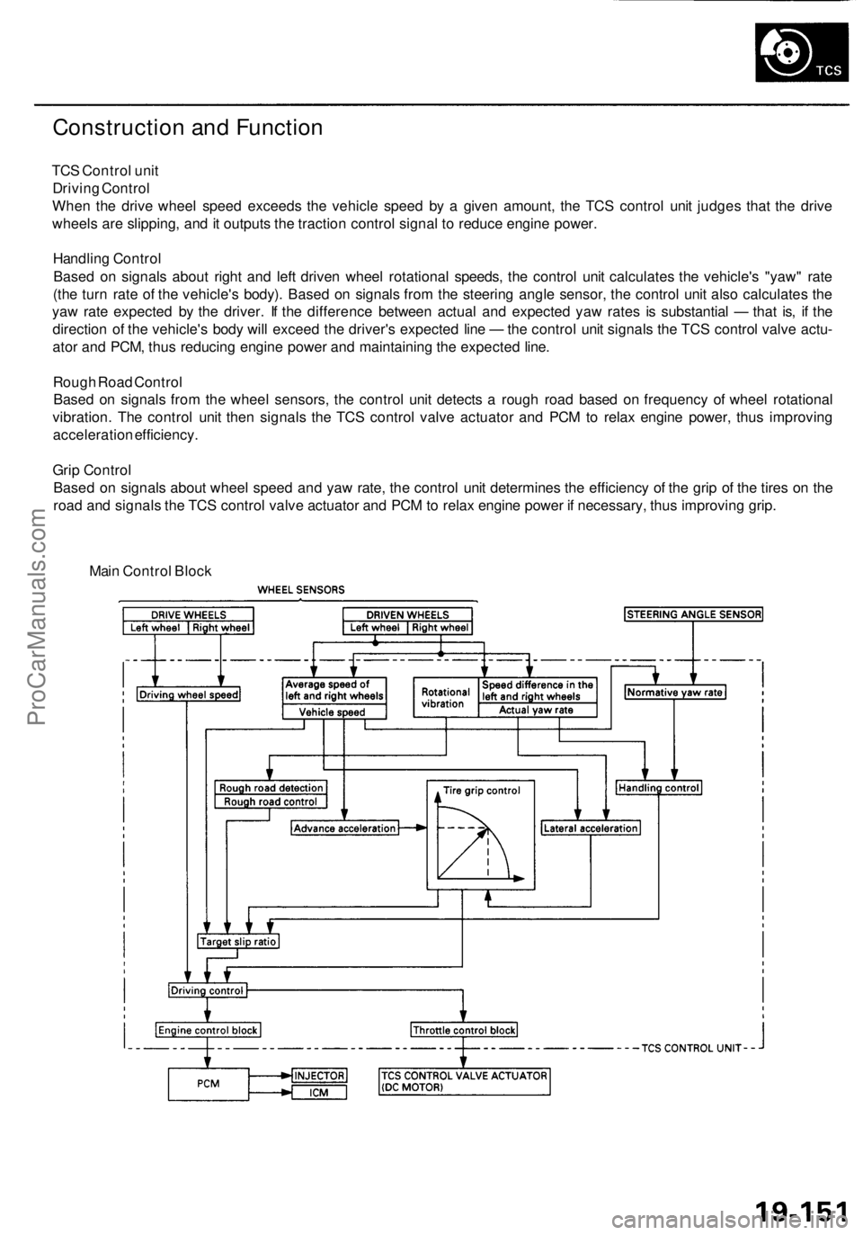
Construction and Function
TCS Control unit
Driving Control
When the drive wheel speed exceeds the vehicle speed by a given amount, the TCS control unit judges that the drive
wheels are slipping, and it outputs the traction control signal to reduce engine power.
Handling Control
Based on signals about right and left driven wheel rotational speeds, the control unit calculates the vehicle's "yaw" rate
(the turn rate of the vehicle's body). Based on signals from the steering angle sensor, the control unit also calculates the
yaw rate expected by the driver. If the difference between actual and expected yaw rates is substantial — that is, if the
direction of the vehicle's body will exceed the driver's expected line — the control unit signals the TCS control valve actu-
ator and PCM, thus reducing engine power and maintaining the expected line.
Rough Road Control
Based on signals from the wheel sensors, the control unit detects a rough road based on frequency of wheel rotational
vibration. The control unit then signals the TCS control valve actuator and PCM to relax engine power, thus improving
acceleration efficiency.
Grip Control
Based on signals about wheel speed and yaw rate, the control unit determines the efficiency of the grip of the tires on the
road and signals the TCS control valve actuator and PCM to relax engine power if necessary, thus improving grip.
Main Control BlockProCarManuals.com