wheel ACURA RL KA9 1996 Service Owners Manual
[x] Cancel search | Manufacturer: ACURA, Model Year: 1996, Model line: RL KA9, Model: ACURA RL KA9 1996Pages: 1954, PDF Size: 61.44 MB
Page 1239 of 1954
Troubleshooting Precaution s
System Indicator s
If th e syste m is OK , th e AB S indicato r goe s of f onc e afte r turnin g th e ignitio n switc h O N (II ) withou t startin g th e engine ,
an d the n com e o n agai n an d g o of f severa l second s late r afte r startin g th e engine . Thi s occur s becaus e th e VS A contro l
uni t i s turne d o n b y th e IG 2 powe r source .
Th e AB S indicato r o r VS A syste m indicato r come s o n whe n th e VS A contro l uni t detect s a proble m in th e system .
Th e AB S indicato r o r VS A syste m indicato r wil l als o com e o n unde r thes e conditions , eve n thoug h th e syste m is oper -
atin g properly :
— Th e vehicl e goe s int o a spi n
— Th e AB S continue s t o operat e fo r a lon g tim e
— Th e vehicl e is subjecte d to a n electrica l signa l disturbanc e
I f ther e is a faul t i n th e PGM-F I system , onl y th e VS A syste m indicato r come s on .
Th e VS A Activatio n Indicato r wil l flas h whe n onl y th e driv e wheel s rotat e o r on e o f th e driv e wheel s is stuck . Whe n thi s
occurs , th e AB S indicato r an d VS A syste m indicato r d o no t com e on .
T o determin e th e actua l caus e o f th e problem , questio n th e custome r abou t th e problem , takin g thes e condition s int o con -
sideration .
Whe n a proble m is detecte d an d th e AB S o r VS A indicato r come s on , ther e ar e case s whe n th e indicato r stay s o n unti l
th e ignitio n switc h i s turne d OFF , an d case s whe n th e indicato r goe s of f automaticall y whe n th e syste m return s t o nor -
mal . Fo r DT C 6 1 an d 62 , th e indicato r goe s of f automaticall y whe n th e syste m return s t o normal . Fo r al l othe r codes ,
th e indicato r stay s o n unti l th e ignitio n switc h is turne d OFF .
Fo r DTC s 12 , 14 , 16 , 18 , 51 , 52 , 53 , 66 , 6 8 an d 84 , th e AB S indicato r goe s of f whe n th e vehicl e is drive n agai n an d th e
syste m is O K afte r th e ignitio n switc h is turne d fro m OF F to O N (II) . However , i f th e DT C is cleared , th e CP U reset s an d
th e indicato r goe s of f righ t afte r th e engin e is starte d if th e syste m is OK .
Th e AB S is no t operationa l whe n th e AB S indicato r i s ON ; th e VS A is no t operationa l whe n th e VS A indicato r i s ON .
Whe n th e VS A indicato r an d MI L ar e bot h ON , troubleshoo t th e PGM-F I syste m first .
Diagnosti c Troubl e Cod e (DTC )
Th e memor y ca n hol d an y numbe r o f DTCs . However , whe n th e sam e DT C is detecte d mor e tha n once , th e mor e recen t
DT C is writte n ove r th e earlie r one . Therefore , whe n th e sam e proble m is detecte d repeatedly , i t i s memorize d a s a sin -
gle DTC .
The DTC s ar e indicate d in ascendin g numbe r order , no t i n th e orde r the y occur .
Th e DTC s ar e memorize d in th e EEPRO M (non-volatil e memory) . Therefore , th e memorize d DTC s canno t b e cancele d
b y disconnectin g th e battery . Perfor m th e specifie d procedure s to clea r th e DTCs .
Self-diagnosi s
Self-diagnosis can be classifie d int o tw o categories :
— Initia l diagnosis : Performe d righ t afte r th e engin e start s an d unti l th e AB S o r VS A indicato r goe s off .
— Regula r diagnosis : Performe d righ t afte r th e initia l diagnosi s unti l th e ignitio n switc h is turne d OFF .
When a proble m is detecte d b y self-diagnosis , th e VS A contro l uni t shift s to fail-saf e mode .
Kickbac k
The pum p moto r operate s whe n th e AB S is functioning , an d th e flui d in th e reservoi r i s force d ou t t o th e maste r cylinder ,
causing kickbac k a t th e brak e pedal .
Pum p Moto r
Th e pum p moto r operate s whe n th e AB S is functioning .
The VS A contro l uni t check s th e pum p moto r operatio n durin g initia l diagnosi s whe n th e vehicl e is started .
You ma y hea r th e moto r operat e a t thi s time , bu t i t i s normal .
Brak e Flui d Replacement/Ai r Bleedin g
Brak e flui d replacemen t an d ai r bleedin g procedure s ar e identica l t o th e procedure s us e o n vehicle s no t equippe d wit h
VSA . T o eas e bleeding , star t wit h th e fron t wheels .
ProCarManuals.com
Page 1256 of 1954
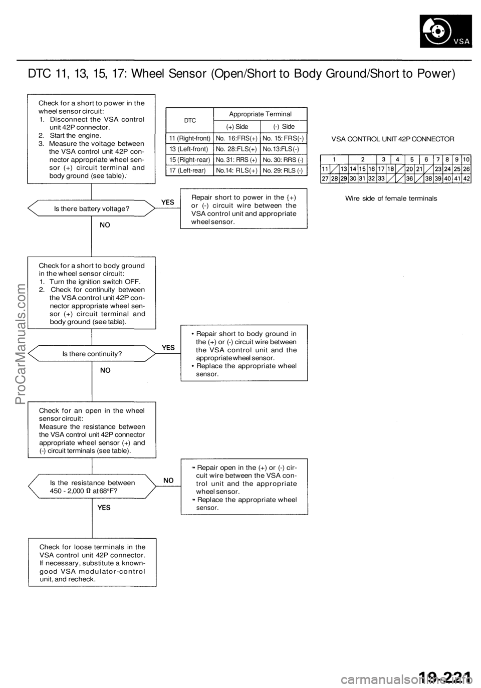
DTC 11, 13, 15, 17: Wheel Sensor (Open/Short to Body Ground/Short to Power)
Check for a short to power in the
wheel sensor circuit:
1. Disconnect the VSA control
unit 42P connector.
2. Start the engine.
3. Measure the voltage between
the VSA control unit 42P con-
nector appropriate wheel sen-
sor (+) circuit terminal and
body ground (see table).
DTC
11 (Right-front)
13 (Left-front)
15 (Right-rear)
17 (Left-rear)
Appropriate Terminal
(+) Side
No. 16:FRS(+)
No. 28:FLS(+)
No. 31: RRS (+)
No.14: RLS(+)
(-) Side
No. 15: FRS(-)
No. 13:FLS (-)
No. 30:
RRS
(-)
No. 29: RLS (-)
VSA CONTROL UNIT 42P CONNECTOR
Is there battery voltage?
Repair short to power in the {+)
or (-) circuit wire between the
VSA control unit and appropriate
wheel sensor.
Wire side of female terminals
Check for a short to body ground
in the wheel sensor circuit:
1. Turn the ignition switch OFF.
2. Check for continuity between
the VSA control unit 42P con-
nector appropriate wheel sen-
sor (+) circuit terminal and
body ground (see table).
Is there continuity?
Repair short to body ground in
the (+) or (-) circuit wire between
the VSA control unit and the
appropriate wheel sensor.
Replace the appropriate wheel
sensor.
Check for an open in the wheel
sensor circuit:
Measure the resistance between
the VSA control unit 42P connector
appropriate wheel sensor (+) and
(-) circuit terminals (see table).
Is the resistance between
450 - 2,000 at 68°F?
• Repair open in the (+) or (-) cir-
cuit wire between the VSA con-
trol unit and the appropriate
wheel sensor.
• Replace the appropriate wheel
sensor.
Check for loose terminals in the
VSA control unit 42P connector.
If necessary, substitute a known-
good VSA modulator-control
unit, and recheck.ProCarManuals.com
Page 1257 of 1954
Troubleshooting
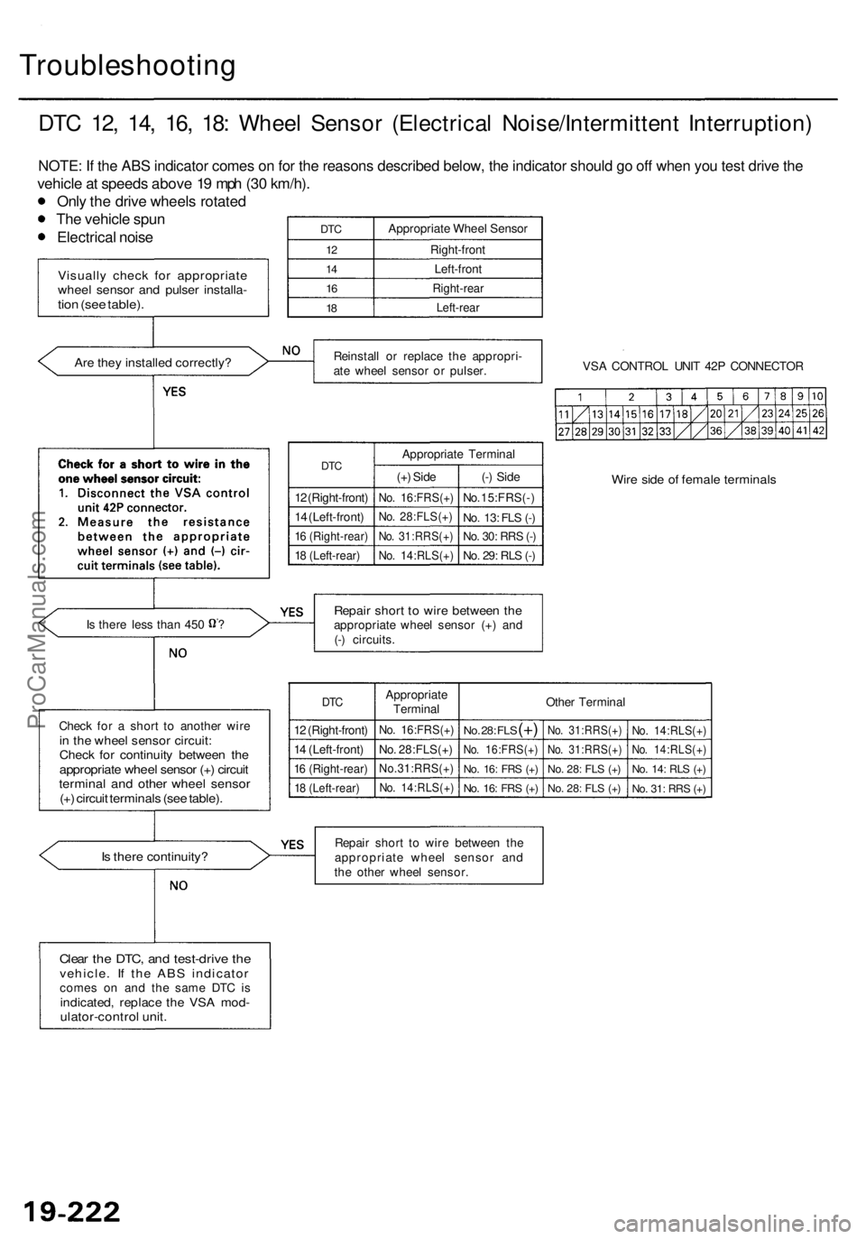
DTC 12 , 14 , 16 , 18 : Whee l Senso r (Electrica l Noise/Intermitten t Interruption )
NOTE: If the ABS indicator comes on for the reasons described below, the indicator should go off when you test drive the
vehicle a t speed s abov e 1 9 mp h (3 0 km/h) .
Onl y th e driv e wheel s rotate d
Th e vehicl e spu n
Electrica l nois e
Is ther e continuity ?
DTC
12
1 4
16
18
Appropriat e Whee l Senso r
Right-fron t
Left-fron t
Right-rea r
Left-rear
Reinstal l o r replac e th e appropri -
at e whee l senso r o r pulser . VS
A CONTRO L UNI T 42 P CONNECTO R
DTC
12 (Right-front )
1 4 (Left-front )
16 (Right-rear )
18 (Left-rear )
Appropriat e Termina l
(+ ) Sid e
No. 16:FRS(+ )
No. 28:FLS(+ )
No. 31:RRS(+ )
No. 14:RLS(+ )
(-) Sid e
No. 15:FRS( - )
No . 13 : FL S (- )
No . 30 : RR S (- )
No . 29 : RL S (- )
Wir e sid e o f femal e terminal s
Repair shor t t o wir e betwee n th eappropriat e whee l senso r (+ ) an d
(- ) circuits .
DTC
12 (Right-front )
1 4 (Left-front )
16 (Right-rear )
18 (Left-rear )
Appropriat e
Termina l
No. 16:FRS(+ )
No. 28:FLS(+ )
No.31:RRS(+ )
No. 14:RLS(+ )
Other Termina l
No. 28 : FL S (+)
No . 16:FRS(+ )
No. 16 : FR S (+ )
No . 16 : FR S (+ )
No . 31:RRS(+ )
No . 31:RRS(+ )
No. 28 : FL S (+ )
No . 28 : FL S (+ )
No . 14:RLS(+ )
No. 14:RLS(+ )
No. 14 : RL S (+ )
No . 31 : RR S (+ )
Repai r shor t t o wir e betwee n th e
appropriat e whee l senso r an d
th e othe r whee l sensor .
Clear th e DTC , an d test-driv e th evehicle . I f th e AB S indicato rcomes o n an d th e sam e DT C i sindicated , replac e th e VS A mod -ulator-contro l unit .
Chec k fo r a shor t t o anothe r wir ein th e whee l senso r circuit :Check fo r continuit y betwee n th eappropriat e whee l senso r (+ ) circui ttermina l an d othe r whee l senso r(+) circui t terminal s (se e table) .
Is ther e les s tha n 45 0 ?
Visuall y chec k fo r appropriat ewheel senso r an d pulse r installa -tion (se e table) .
Are the y installe d correctly ?
ProCarManuals.com
Page 1258 of 1954
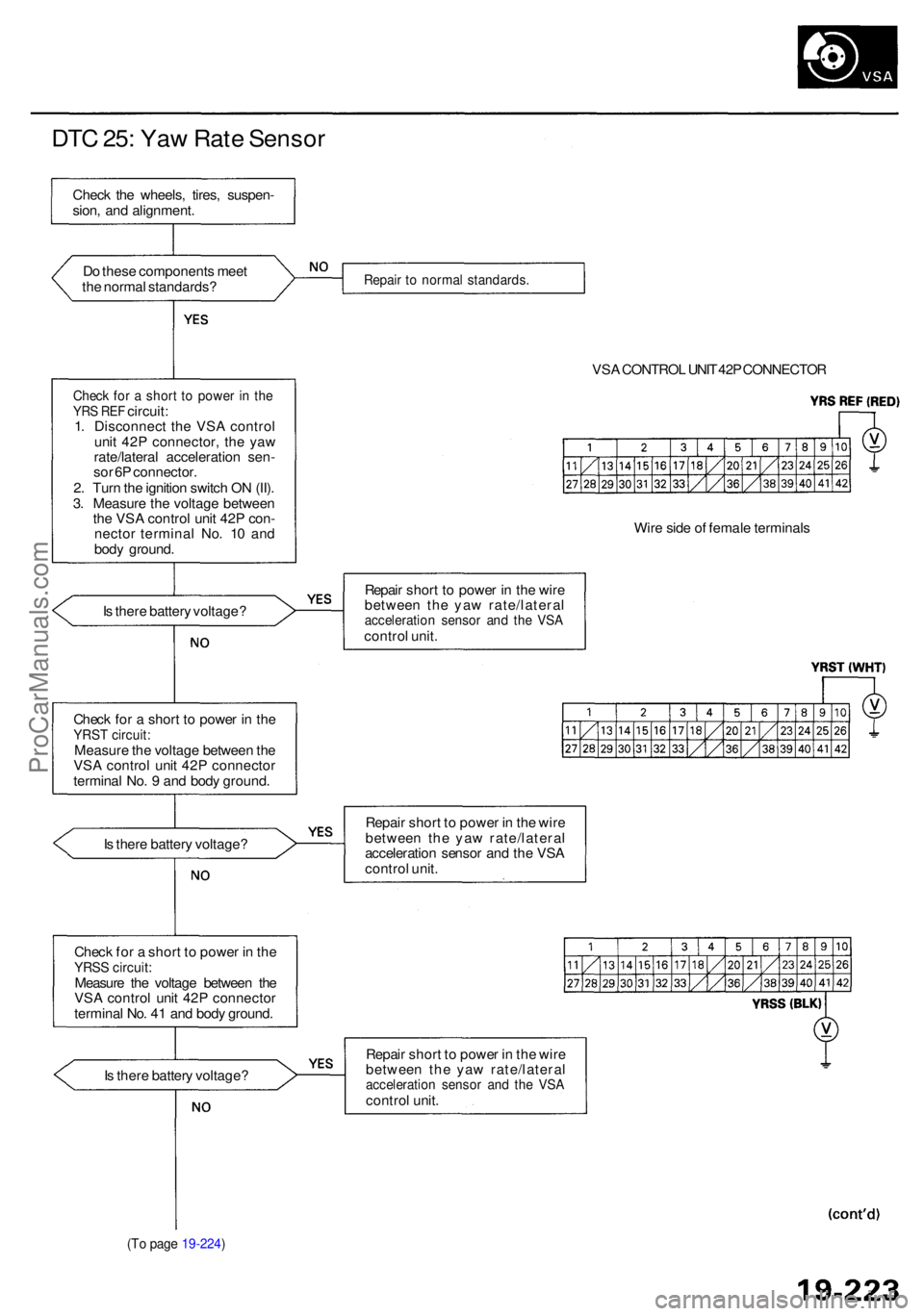
DTC 25 : Ya w Rat e Senso r
Do thes e component s mee t
th e norma l standards ?
Check fo r a shor t t o powe r i n th eYR S RE F circuit :
1 . Disconnec t th e VS A contro l
uni t 42 P connector , th e ya w
rate/latera l acceleratio n sen -
so r 6 P connector .
2 . Tur n th e ignitio n switc h O N (II) .
3 . Measur e th e voltag e betwee n
th e VS A contro l uni t 42 P con -
necto r termina l No . 1 0 an d
bod y ground .
I s ther e batter y voltage ?
Chec k fo r a shor t t o powe r i n th e
YRS T circuit :Measur e th e voltag e betwee n th e
VS A contro l uni t 42 P connecto r
termina l No . 9 an d bod y ground .
I s ther e batter y voltage ?
Chec k fo r a shor t t o powe r i n th e
YRS S circuit :Measur e th e voltag e betwee n th e
VS A contro l uni t 42 P connecto r
termina l No . 4 1 an d bod y ground .
I s ther e batter y voltage ?
(To pag e 19-224 )
Repair t o norma l standards .
VSA CONTRO L UNI T 42 P CONNECTO R
Wir e sid e o f femal e terminal s
Repai r shor t t o powe r i n th e wir e
betwee n th e ya w rate/latera l
acceleration senso r an d th e VS Acontro l unit .
Repai r shor t t o powe r i n th e wir e
betwee n th e ya w rate/latera l
acceleratio n senso r an d th e VS A
contro l unit .
Repai r shor t t o powe r i n th e wir e
betwee n th e ya w rate/latera l
acceleration senso r an d th e VS Acontro l unit .
Chec
k th e wheels , tires , suspen -
sion , an d alignment .
ProCarManuals.com
Page 1261 of 1954
Troubleshooting
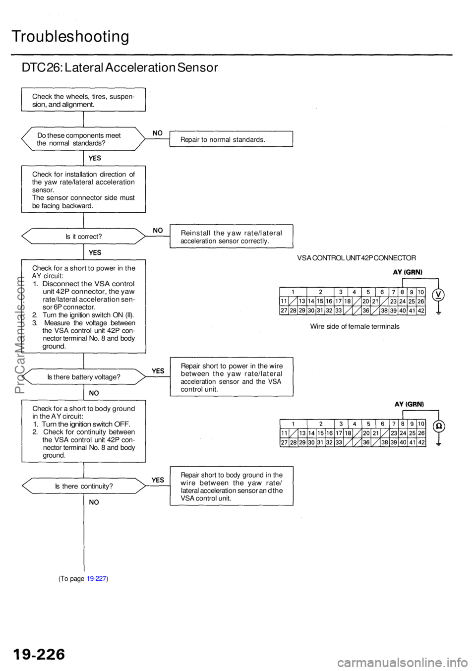
DTC 26 : Latera l Acceleratio n Senso r
Check th e wheels , tires , suspen -sion, an d alignment .
Do thes e component s mee t
th e norma l standards ?
Chec k fo r installatio n directio n o f
th e ya w rate/latera l acceleratio n
sensor.The senso r connecto r sid e mus t
b e facin g backward .
Is i t correct ?
Check fo r a shor t t o powe r i n th eAY circuit :1. Disconnec t th e VS A contro lunit 42 P connector , th e ya wrate/latera l acceleratio n sen -
so r 6 P connector .
2 . Tur n th e ignitio n switc h O N (II) .
3 . Measur e th e voltag e betwee n
th e VS A contro l uni t 42 P con -
necto r termina l No . 8 an d bod y
ground .
Is ther e batter y voltage ?
Chec k fo r a shor t t o bod y groun d
i n th e A Y circuit :
1. Tur n th e ignitio n switc h OFF .2. Chec k fo r continuit y betwee n
th e VS A contro l uni t 42 P con -
necto r termina l No . 8 an d bod y
ground .
I s ther e continuity ?
(To pag e 19-227 )
Repair t o norma l standards .
Reinstall th e ya w rate/latera lacceleration senso r correctly .
VSA CONTRO L UNI T 42 P CONNECTO R
Wir e sid e o f femal e terminal s
Repai r shor t t o powe r i n th e wir e
betwee n th e ya w rate/latera l
acceleration senso r an d th e VS Acontro l unit .
Repai r shor t t o bod y groun d in th ewir e betwee n th e ya w rate /lateral acceleratio n senso r a n d th e
VS A contro l unit .
ProCarManuals.com
Page 1279 of 1954

Troubleshooting
DTC 71: Abnormal Wheel Speed Signal
Are any DTCs except 71 indicated?
Check the tires.
Are tires with specified size and
inflated to specification?
Check for brake drag.
Do the brakes drag?
Visually check for appropriate
wheel sensor and pulser installa-
tion (see table).
Are they installed correctly?
Check the four pulser gears for a
chipped tooth (see table).
Is the pulser OK?
Problem Verification:
1. Clear the DTC.
2. Test-drive the vehicle at 19
mph (30 km/h) or more.
3. Verify the DTC.
Is DTC 71 indicated?
YES
Check for loose terminals in the
VSA control unit 42P connector.
If necessary, substitute a known-
good VSA modulator-control
unit, and recheck.
Preform the appropriate trou-
bleshooting for the DTC.
Replace the tire(s) with the spec-
ified size.
Repair the brake drag.
Reinstall or replace the wheel
sensor or pulser.
Replace the driveshaft or hub
unit. (Chipped pulser gear.)
The system is OK at this time.
Verify the DTC.ProCarManuals.com
Page 1283 of 1954
Troubleshooting
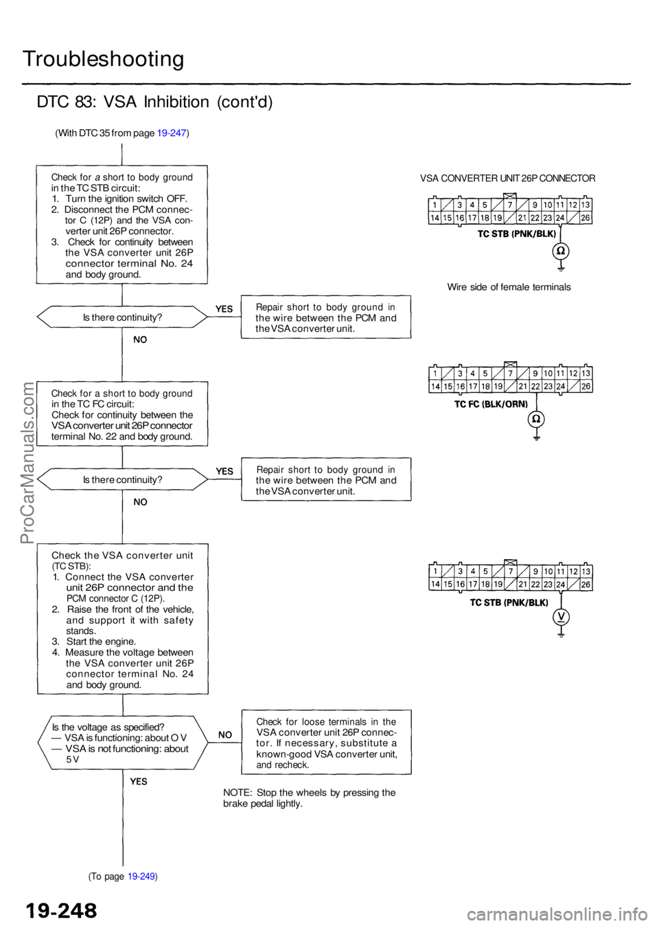
DTC 83 : VS A Inhibitio n (cont'd )
(With DT C 35 fro m pag e 19-247 )
Check fo r a shor t t o bod y groun din th e T C ST B circuit :
1 . Tur n th e ignitio n switc h OFF .
2 . Disconnec t th e PC M connec -
tor C (12P ) and th e VS A con -verte r uni t 26 P connector .
3 . Chec k fo r continuit y betwee n
th e VS A converte r uni t 26 P
connecto r termina l No . 2 4an d bod y ground .
I s ther e continuity ?
Check fo r a shor t t o bod y groun din th e T C F C circuit :
Chec k fo r continuit y betwee n th e
VS A converte r uni t 26 P connecto rterminal No . 2 2 an d bod y ground .
I s ther e continuity ?
Chec k the VSA converte r uni t
(TC STB) :1. Connec t th e VS A converte runit 26 P connecto r an d th ePC M connecto r C (12P) .2. Rais e th e fron t o f th e vehicle ,
an d suppor t i t wit h safet y
stands.3. Star t th e engine .
4 . Measur e th e voltag e betwee n
th e VS A converte r uni t 26 P
connecto r termina l No . 2 4
an d bod y ground .
I s th e voltag e a s specified ?
— VS A is functioning : abou t O V
— VS A is no t functioning : abou t5V
(T o pag e 19-249 )
VSA CONVERTE R UNI T 26 P CONNECTO R
Wire sid e o f femal e terminal s
Repair shor t t o bod y groun d i nth e wir e betwee n th e PC M an d
th e VS A converte r unit .
Repai r shor t t o bod y groun d i nth e wir e betwee n th e PC M an d
th e VS A converte r unit .
Chec k fo r loos e terminal s i n th eVS A converte r uni t 26 P connec -
tor . I f necessary , substitut e a
known-goo d VS A converte r unit ,
and recheck .
NOTE: Sto p th e wheel s b y pressin g th e
brak e peda l lightly .
ProCarManuals.com
Page 1284 of 1954
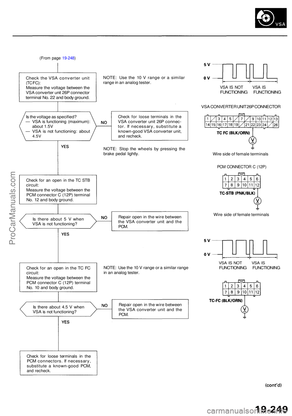
(From pag e 19-248 )
Check th e VS A converte r uni t(TC FC) :Measur e th e voltag e betwee n th e
VS A converte r uni t 26 P connecto r
terminal No . 2 2 an d bod y ground .
NOTE: Us e th e 1 0 V rang e o r a simila r
rang e in a n analo g tester .
VSA IS NO T VS A ISFUNCTIONIN G FUNCTIONIN G
VS A CONVERTE R UNI T 26 P CONNECTO R
I s th e voltag e a s specified ?
— VS A is functionin g (maximum) :
abou t 1.5 V
— VS A is no t functioning : abou t
4.5V
Chec k fo r loos e terminal s i n th eVSA converte r uni t 26 P connec -
tor . I f necessary , substitut e a
known-goo d VS A converte r unit ,
and recheck .
NOTE: Sto p th e wheel s b y pressin g th e
brak e peda l lightly .
Check fo r a n ope n i n th e T C ST Bcircuit :Measur e th e voltag e betwee n th e
PC M connecto r C (12P ) termina l
No . 1 2 an d bod y ground . Wir
e sid e o f femal e terminal s
PCM CONNECTO R C (12P )
Is ther e abou t 5 V whe n
VS A is no t functioning ? Repai
r ope n in th e wir e betwee n
th e VS A converte r uni t an d th e
PCM .
Wire sid e o f femal e terminal s
Chec k fo r a n ope n in th e T C F C
circuit :Measur e th e voltag e betwee n th e
PC M connecto r C (12P ) termina l
No . 1 0 an d bod y ground . NOTE
: Us e th e 1 0 V rang e o r a simila r rang e
i n a n analo g tester .
VSA IS NO T VS A ISFUNCTIONIN G FUNCTIONIN G
I s ther e abou t 4. 5 V whe n
VS A is no t functioning ? Repai
r ope n in th e wir e betwee n
th e VS A converte r uni t an d th e
PCM .
Chec k fo r loos e terminal s i n th e
PC M connectors . I f necessary ,
substitut e a known-goo d PCM ,
and recheck .
ProCarManuals.com
Page 1304 of 1954

VSA Modulator-Control Unit
Removal/Installation
NOTE:
Do not spill brake fluid on the vehicle; it may damage the paint; if brake fluid does contact the paint, wash it off imme-
diately with water.
Take care not to damage or deform the brake lines during removal and installation.
To prevent the brake fluid from flowing, plug and cover the hose ends and joints with a shop towel or equivalent material.
Removal
1. Disconnect the pressure sensor 3P connector.
2. Pull the locking lever of the VSA control unit 42P connec-
tor up, then disconnect the connector.
3. Disconnect the six brake lines.
4. Remove the two 8 mm nuts.
5. Remove the VSA modulator-control unit.
Installation
1. Install the VSA modulator-control unit, then tighten the
two 8 mm nuts.
2. Align the connecting surfaces of the VSA control unit 42P
connector.
3. Push the locking lever of the VSA control unit 42P connec-
tor down until you hear a click.
4. Connect the pressure sensor 3P connector.
5. Connect the six brake lines.
6. Perform the precharge brake line bleeding (see page 19-
271).
7. Bleed the brake system, starting with the front wheels.
8. Start the engine, and check that the ABS indicator goes
off.
9. Test-drive the vehicle, and check that the ABS indicator
does not come on.
To right-rear
To left-rear
PRESSURE SENSOR
3P CONNECTOR
VSA MODULATOR
CONTROL UNIT
LOCKING LEVER
VSA CONTROL UNIT
42P CONNECTOR
To right-front
To left-front
FLARE NUT
15 N-m (1.5 kgf-m, 11 Ibf-ft)
MOUNTING BOLT
VSA CONTROL UNIT 42P CONNECTOR
8 mm BOLT
22 N-m (2.2 kgf-m, 16 Ibf-ft)
8 mm NUT
9 N-m (0.9 kgf-m, 7 Ibf-ft)
RUBBER MOUNT
BRACKETProCarManuals.com
Page 1305 of 1954
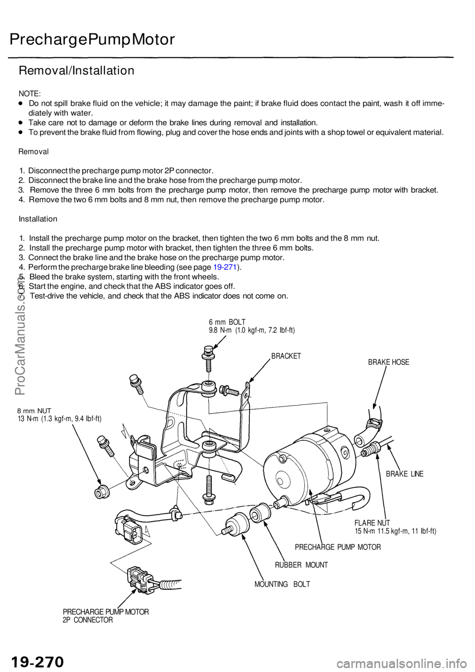
Precharge Pum p Moto r
Removal/Installatio n
NOTE:
Do no t spil l brak e flui d o n th e vehicle ; i t ma y damag e th e paint ; i f brak e flui d doe s contac t th e paint , was h it of f imme -
diatel y wit h water .
Tak e car e no t t o damag e o r defor m th e brak e line s durin g remova l an d installation .
T o preven t th e brak e flui d fro m flowing , plu g an d cove r th e hos e end s an d joint s wit h a sho p towe l o r equivalen t material .
Remova l
1. Disconnec t th e precharg e pum p moto r 2 P connector .
2 . Disconnec t th e brak e lin e an d th e brak e hos e fro m th e precharg e pum p motor .
3 . Remov e th e thre e 6 m m bolt s fro m th e precharg e pum p motor , the n remov e th e precharg e pum p moto r wit h bracket .
4 . Remov e th e tw o 6 m m bolt s an d 8 m m nut , the n remov e th e precharg e pum p motor .
Installatio n
1. Instal l th e precharg e pum p moto r o n th e bracket , the n tighte n th e tw o 6 m m bolt s an d th e 8 m m nut .
2 . Instal l th e precharg e pum p moto r wit h bracket , the n tighte n th e thre e 6 m m bolts .
3 . Connec t th e brak e lin e an d th e brak e hos e o n th e precharg e pum p motor .
4 . Perfor m th e precharg e brak e lin e bleedin g (se e pag e 19-271 ).
5 . Blee d th e brak e system , startin g wit h th e fron t wheels .
6 . Star t th e engine , an d chec k tha t th e AB S indicato r goe s off .
7 . Test-driv e th e vehicle , an d chec k tha t th e AB S indicato r doe s no t com e on .
6 m m BOL T
9. 8 N- m (1. 0 kgf-m , 7. 2 Ibf-ft )
BRAKE HOS E
8 m m NU T13 N- m (1. 3 kgf-m , 9. 4 Ibf-ft )
BRAKE LIN E
FLAR E NU T
1 5 N- m 11. 5 kgf-m , 1 1 Ibf-ft )
PRECHARG E PUM P MOTO R
RUBBE R MOUN T
MOUNTIN G BOL T
PRECHARG E PUM P MOTO R2P CONNECTO R
BRACKET
ProCarManuals.com