ACURA TL 1995 Service Repair Manual
Manufacturer: ACURA, Model Year: 1995, Model line: TL, Model: ACURA TL 1995Pages: 1771, PDF Size: 62.49 MB
Page 1671 of 1771
Rear Windo w Defogge r
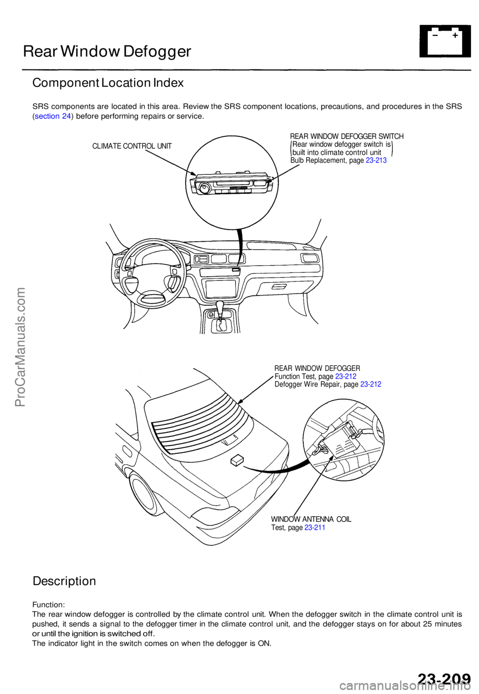
Componen t Locatio n Inde x
SRS component s ar e locate d in thi s area . Revie w th e SR S componen t locations , precautions , an d procedure s in th e SR S
( sectio n 24 ) befor e performin g repair s o r service .
CLIMAT E CONTRO L UNI T
REA R WINDO W DEFOGGE R SWITC HRear windo w defogge r switc h i sbuil t int o climat e contro l uni tBulb Replacement , pag e 23-21 3
REAR WINDO W DEFOGGE RFunction Test , pag e 23-21 2Defogge r Wir e Repair , pag e 23-21 2
WINDO W ANTENN A COI LTest , pag e 23-21 1
Descriptio n
Function:
Th e rea r windo w defogge r i s controlle d b y th e climat e contro l unit . Whe n th e defogge r switc h i n th e climat e contro l uni t i s
pushed , i t send s a signa l t o th e defogge r time r i n th e climat e contro l unit , an d th e defogge r stay s o n fo r abou t 2 5 minute s
or unti l th e ignitio n is switche d off .
The indicato r ligh t i n th e switc h come s o n whe n th e defogge r i s ON .
ProCarManuals.com
Page 1672 of 1771
Troubleshooting
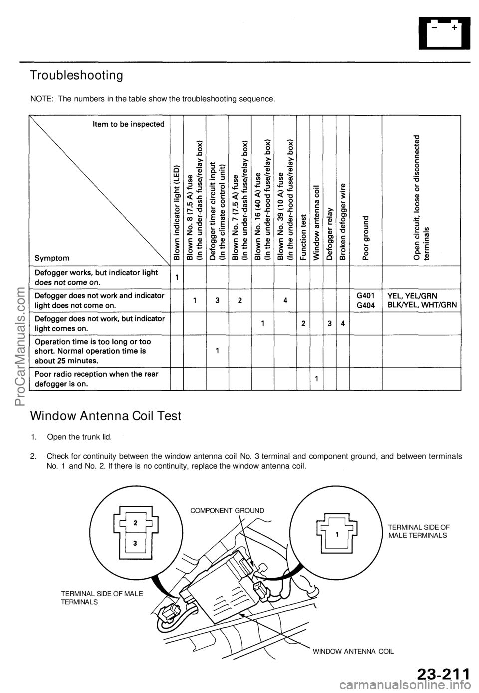
NOTE: Th e number s i n th e tabl e sho w th e troubleshootin g sequence .
Window Antenn a Coi l Tes t
1. Ope n th e trun k lid .
2 . Chec k fo r continuit y betwee n th e windo w antenn a coi l No . 3 termina l an d componen t ground , an d betwee n terminal s
No . 1 an d No . 2 . I f ther e is n o continuity , replac e th e windo w antenn a coil .
TERMINA L SID E O F
MAL E TERMINAL S
TERMINA L SID E O F MAL E
TERMINAL S
WINDOW ANTENN A COI L
COMPONEN
T GROUN D
ProCarManuals.com
Page 1673 of 1771
Rear Windo w Defogge r
Function Tes t
CAUTION : B e carefu l no t t o scratc h o r damag e th e defog -
ger wire s wit h th e teste r probe .
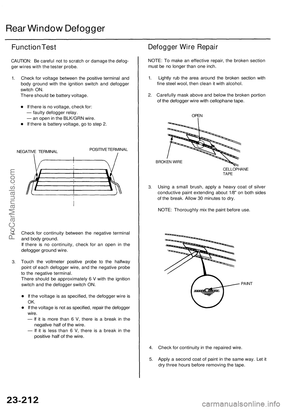
1 . Chec k fo r voltag e betwee n th e positiv e termina l an d
bod y groun d wit h th e ignitio n switc h an d defogge r
switc h ON .
Ther e shoul d b e batter y voltage .
I f ther e is n o voltage , chec k for :
— fault y defogge r relay .
— an ope n in th e BLK/GR N wire .
I f ther e is batter y voltage , g o to ste p 2 .
NEGATIV E TERMINA L POSITIV
E TERMINA L
2.
3 .
Chec k fo r continuit y betwee n th e negativ e termina l
and bod y ground .
If ther e i s n o continuity , chec k fo r a n ope n i n th e
defogge r groun d wire .
Touc h th e voltmete r positiv e prob e t o th e halfwa y
poin t o f eac h defogge r wire , an d th e negativ e prob e
t o th e negativ e terminal .
Ther e shoul d b e approximatel y 6 V with th e ignitio n
switc h an d th e defogge r switc h ON .
I f th e voltag e is a s specified , th e defogge r wir e is
OK .
If th e voltag e is no t a s specified , repai r th e defogge r
wire .
— If i t i s mor e tha n 6 V , ther e i s a brea k i n th e
negativ e hal f o f th e wire .
— If i t i s les s tha n 6 V , ther e i s a brea k i n th e
positiv e hal f o f th e wire .
Defogge r Wir e Repai r
NOTE: T o mak e a n effectiv e repair , th e broke n sectio n
mus t b e n o longe r tha n on e inch .
1 . Lightl y ru b th e are a aroun d th e broke n sectio n wit h
fin e stee l wool , the n clea n it wit h alcohol .
2 . Carefull y mas k abov e an d belo w th e broke n portio n
of th e defogge r wir e wit h cellophan e tape .
OPEN
BROKE N WIR E
CELLOPHAN ETAPE
3.Usin g a smal l brush , apply a heav y coa t o f silve r
conductiv e pain t extendin g abou t 1/8 " o n bot h side s
o f th e break . Allo w 3 0 minute s t o dry .
NOTE : Thoroughl y mi x th e pain t befor e use .
PAIN T
4. Chec k fo r continuit y in th e repaire d wire .
5 . Appl y a secon d coa t o f pain t i n th e sam e way . Le t i t
dr y thre e hour s befor e removin g th e tape .
ProCarManuals.com
Page 1674 of 1771
Switch Ligh t Bul b Replacemen t
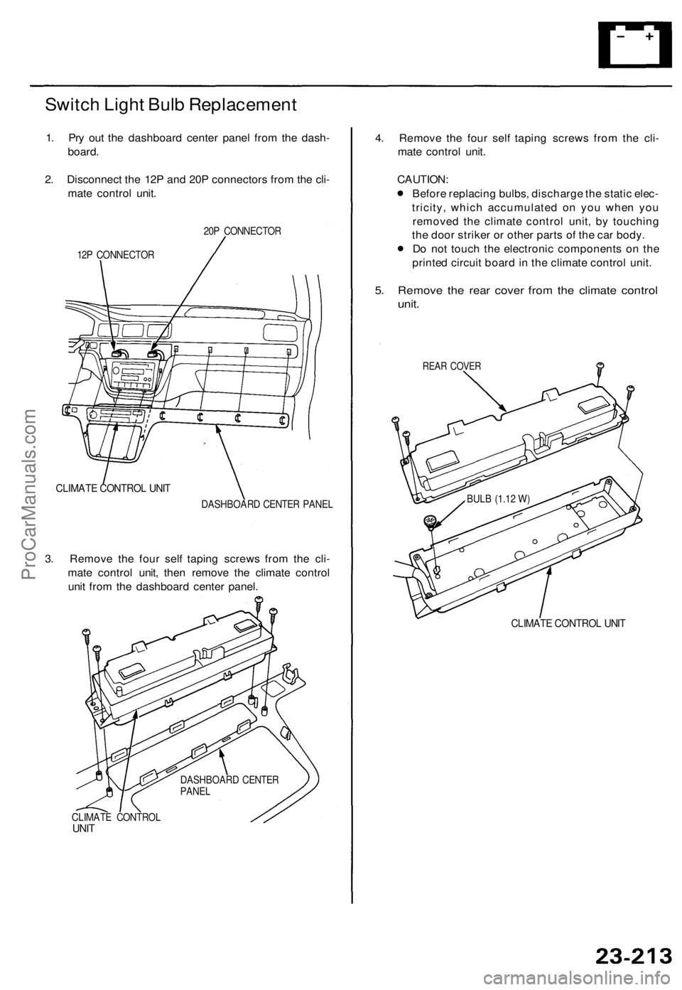
1. Pr y ou t th e dashboar d cente r pane l fro m th e dash -
board .
2 . Disconnec t th e 12 P an d 20 P connector s fro m th e cli -
mat e contro l unit .
20P CONNECTO R
12 P CONNECTO R
CLIMATE CONTRO L UNI T
DASHBOAR D CENTE R PANE L
3. Remov e th e fou r sel f tapin g screw s fro m th e cli -
mat e contro l unit , the n remov e th e climat e contro l
uni t fro m th e dashboar d cente r panel .
CLIMAT E CONTRO LUNIT
4. Remov e th e fou r sel f tapin g screw s fro m th e cli -
mat e contro l unit .
CAUTION :
Befor e replacin g bulbs , discharg e th e stati c elec -
tricity , whic h accumulate d o n yo u whe n yo u
remove d th e climat e contro l unit , b y touchin g
th e doo r strike r o r othe r part s o f th e ca r body .
D o no t touc h th e electroni c component s o n th e
printe d circui t boar d in th e climat e contro l unit .
5. Remov e th e rea r cove r fro m th e climate control
unit.
REA R COVE R
CLIMAT E CONTRO L UNI T
DASHBOAR D CENTE R
PANE L BUL
B (1.1 2 W )
ProCarManuals.com
Page 1675 of 1771
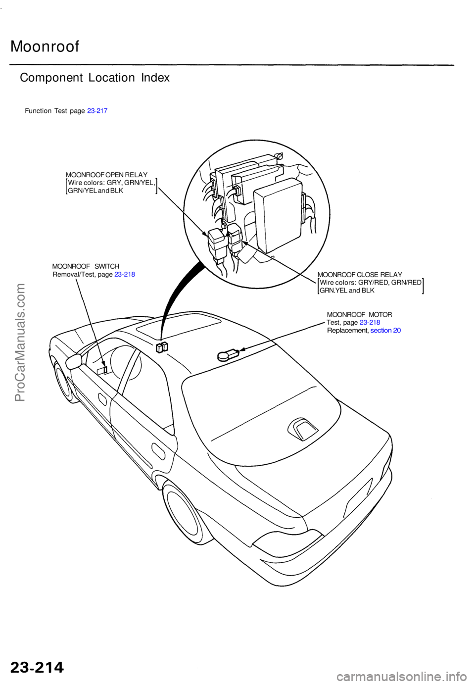
Moonroof
Componen t Locatio n Inde x
Functio n Tes t pag e 23-21 7
MOONROO F OPE N RELA Y
Wir e colors : GRY , GRN/YEL ,
GRN/YEL an d BL K
MOONROO F SWITC H
Removal/Test , pag e 23-21 8
MOONROOF CLOS E RELA Y
Wir e colors : GRY/RED , GRN/RE D
GRN.YEL an d BL K
MOONROO F MOTO R
Test , pag e 23-21 8
Replacement , sectio n 2 0
ProCarManuals.com
Page 1676 of 1771
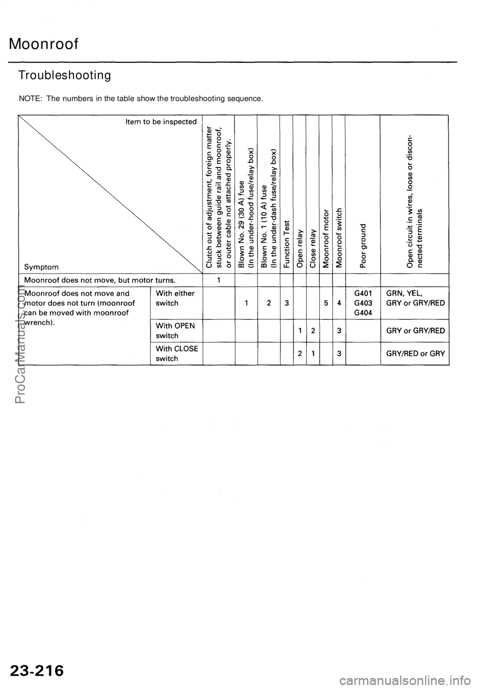
Moonroof
Troubleshootin g
NOTE: Th e number s i n th e tabl e sho w th e troubleshootin g sequence .
ProCarManuals.com
Page 1677 of 1771
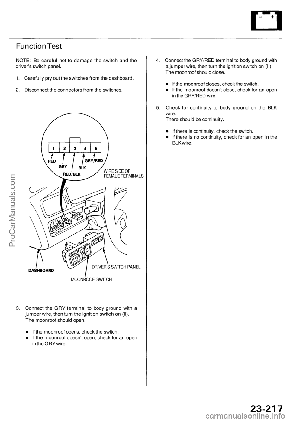
Function Tes t
NOTE : B e carefu l no t t o damag e th e switc h an d th e
driver' s switc h panel .
1 . Carefull y pr y ou t th e switche s fro m th e dashboard .
2 . Disconnec t th e connector s fro m th e switches .
WIRE SID E O F
FEMAL E TERMINAL S
DRIVER' S SWITC H PANE L
MOONROO F SWITC H
3. Connec t th e GR Y termina l t o bod y groun d wit h a
jumpe r wire , the n tur n th e ignitio n switc h o n (II) .
The moonroo f shoul d open .
I f th e moonroo f opens , chec k th e switch .
I f th e moonroo f doesn' t open , chec k fo r a n ope n
i n th e GR Y wire . 4
. Connec t th e GRY/RE D termina l t o bod y groun d wit h
a jumpe r wire , the n tur n th e ignitio n switc h o n (II) .
Th e moonroo f shoul d close .
I f th e moonroo f closes , chec k th e switch .
I f th e moonroo f doesn' t close , chec k fo r a n ope n
in th e GRY/RE D wire .
5. Chec k fo r continuit y t o bod y groun d o n th e BL K
wire .
Ther e shoul d b e continuity .
I f ther e is continuity , chec k th e switch .
I f ther e is n o continuity , chec k fo r a n ope n in th e
BL K wire .
ProCarManuals.com
Page 1678 of 1771
Moonroof
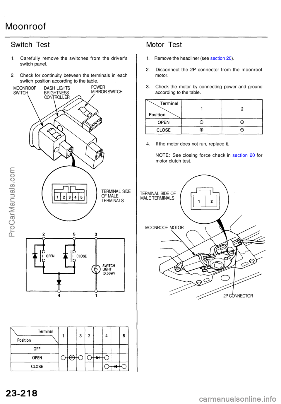
Switch Tes t Motor Tes t
1. Carefull y remov e th e switche s fro m th e driver' s
switch panel .
2. Chec k fo r continuit y betwee n th e terminal s i n eac h
switc h positio n accordin g to th e table .
MOONROO F DAS H LIGHT S
SWITC H BRIGHTNES S
CONTROLLER
POWERMIRRO R SWITC H
TERMINA L SID E
O F MAL E
TERMINAL S
1. Remov e th e headline r (se e sectio n 20 ).
2 . Disconnec t th e 2 P connecto r fro m th e moonroo f
motor .
3 . Chec k th e moto r b y connectin g powe r an d groun d
accordin g to th e table .
4 . I f th e moto r doe s no t run , replac e it .
NOTE : Se e closin g forc e chec k i n sectio n 2 0 fo r
moto r clutc h test .
TERMINA L SID E O F
MAL E TERMINAL S
MOONROO F MOTO R
2P CONNECTO R
ProCarManuals.com
Page 1679 of 1771
Power Mirror s
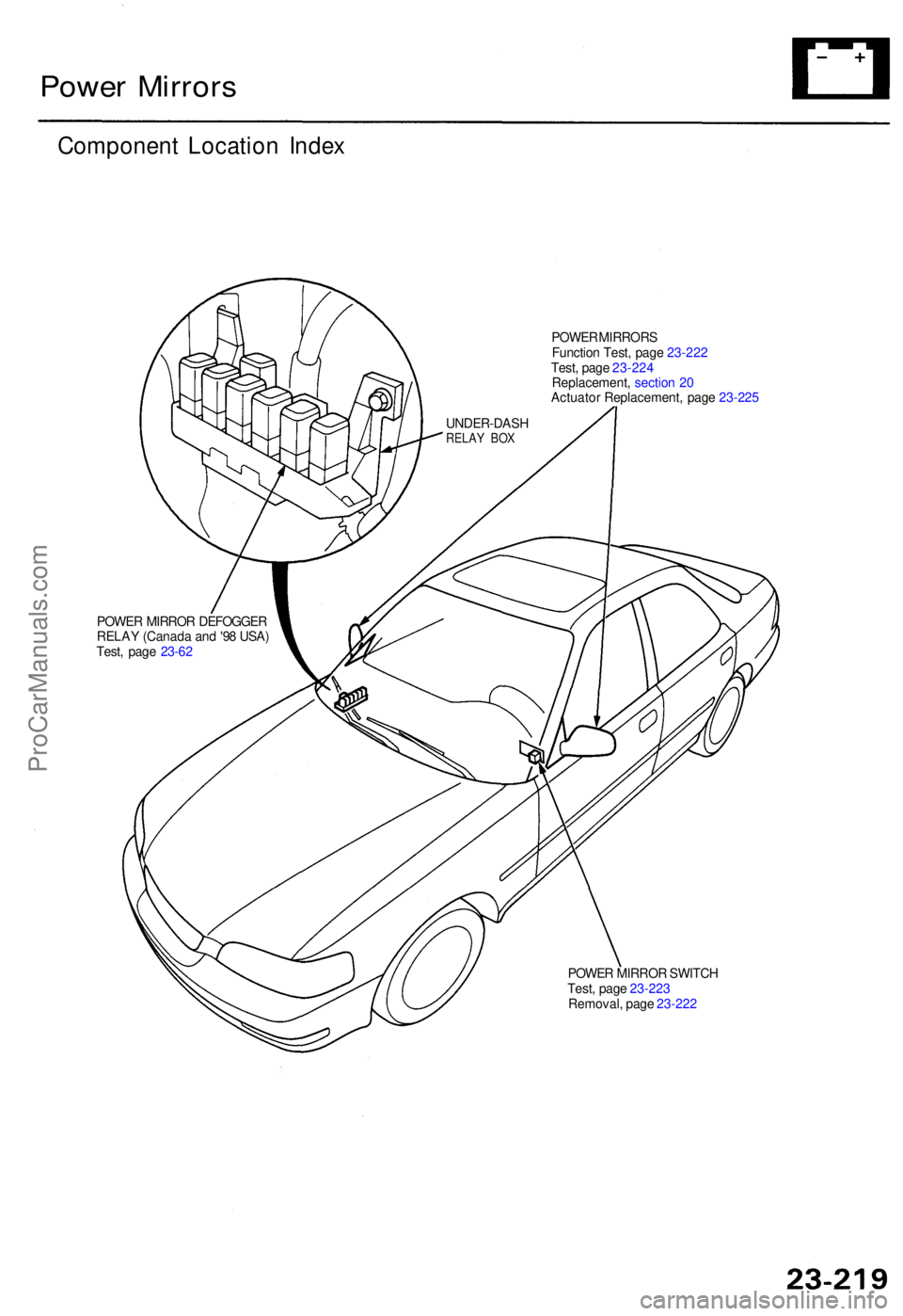
Componen t Locatio n Inde x
POWE R MIRROR S
Functio n Test , pag e 23-22 2
Test , pag e 23-22 4
Replacement , sectio n 2 0
Actuato r Replacement , pag e 23-22 5
POWE R MIRRO R DEFOGGE R
RELA Y (Canad a an d '9 8 USA )
Test , pag e 23-6 2
POWER MIRRO R SWITC H
Test , pag e 23-22 3
Removal , pag e 23-22 2
UNDER-DAS
H
RELAY BO X
ProCarManuals.com
Page 1680 of 1771
Power Mirror s
Functio n Tes t
NOTE : B e carefu l no t t o damag e th e switc h an d th e
driver' s switc h panel .
1 . Carefull y pr y ou t th e switche s fro m th e dashboard .
2 . Disconnec t th e connector s fro m th e switches .
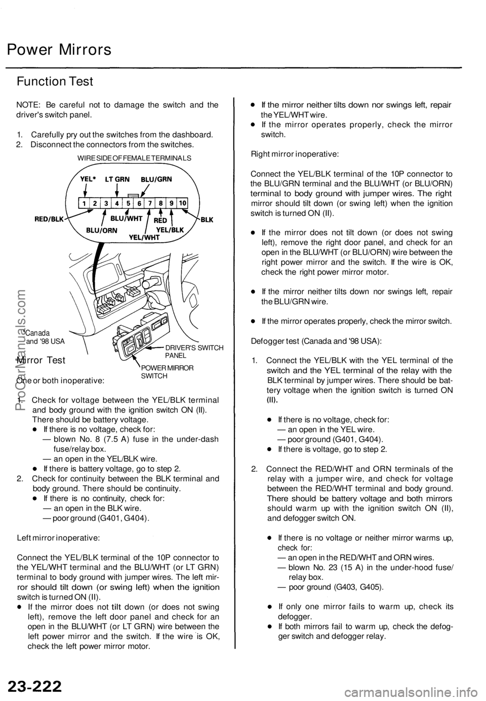
WIRE SID E O F FEMAL E TERMINAL S
*Canadaand '9 8 US A
Mirro r Tes t
One o r bot h inoperative :
DRIVER'S SWITC HPANEL
POWE R MIRRO RSWITCH
1. Chec k fo r voltag e betwee n th e YEL/BL K termina l
an d bod y groun d wit h th e ignitio n switc h O N (II) .
Ther e shoul d b e batter y voltage .
I f ther e is n o voltage , chec k for :
— blow n No . 8 (7. 5 A ) fus e i n th e under-das h
fuse/rela y box .
— an ope n in th e YEL/BL K wire .
I f ther e is batter y voltage , g o to ste p 2 .
2 . Chec k fo r continuit y betwee n th e BL K termina l an d
bod y ground . Ther e shoul d b e continuity .
I f ther e i s n o continuity , chec k for :
— an ope n in th e BL K wire .
— poo r groun d (G401 , G404) .
Lef t mirro r inoperative :
Connec t th e YEL/BL K termina l o f th e 10 P connecto r t o
th e YEL/WH T termina l an d th e BLU/WH T (o r L T GRN )
termina l t o bod y groun d wit h jumpe r wires . Th e lef t mir -
ror shoul d til t dow n (o r swin g left ) whe n th e ignitio n
switch is turne d O N (II) .
I f th e mirro r doe s no t
tilt dow n (o r doe s no t swin g
left) , remov e th e lef t doo r pane l an d chec k fo r a n
ope n in th e BLU/WH T (o r L T GRN ) wir e betwee n th e
lef t powe r mirro r an d th e switch . I f th e wir e i s OK ,
chec k th e lef t powe r mirro r motor .
If th e mirro r neithe r tilt s dow n no r swing s left , repai r
the YEL/WH T wire .
I f th e mirro r operate s properly , chec k th e mirro r
switch .
Righ t mirro r inoperative :
Connec t th e YEL/BL K termina l o f th e 10 P connecto r t o
th e BLU/GR N termina l an d th e BLU/WH T (o r BLU/ORN )
terminal t o bod y groun d wit h jumpe r wires . Th e righ t
mirro r shoul d til t dow n (o r swin g left ) whe n th e ignitio n
switc h is turne d O N (II) .
I f th e mirro r doe s no t til t dow n (o r doe s no t swin g
left) , remov e th e righ t doo r panel , an d chec k fo r a n
ope n in th e BLU/WH T (o r BLU/ORN ) wir e betwee n th e
righ t powe r mirro r an d th e switch . I f th e wir e i s OK ,
chec k th e righ t powe r mirro r motor .
I f th e mirro r neithe r tilt s dow n no r swing s left , repai r
th e BLU/GR N wire .
I f th e mirro r operate s properly , chec k th e mirro r switch .
Defogge r tes t (Canad a an d '9 8 USA) :
1 . Connec t th e YEL/BL K wit h th e YE L termina l o f th e
switc h an d th e YE L termina l o f th e rela y wit h th e
BL K termina l b y jumpe r wires . Ther e shoul d b e bat -
ter y voltag e whe n th e ignitio n switc h i s turne d O N
I f ther e is n o voltage , chec k for :
— an ope n in th e YE L wire .
— poo r groun d (G401 , G404) .
I f ther e is voltage , g o to ste p 2 .
2 . Connec t th e RED/WH T an d OR N terminal s o f th e
rela y wit h a jumpe r wire , an d chec k fo r voltag e
betwee n th e RED/WH T termina l an d bod y ground .
There shoul d b e batter y voltag e an d bot h mirror s
should war m u p wit h th e ignitio n switc h O N (II) ,
an d defogge r switc h ON .
I f ther e is n o voltag e o r neithe r mirro r warm s up ,
chec k for :
— an ope n in th e RED/WH T an d OR N wires .
— blow n No . 2 3 (1 5 A ) i n th e under-hoo d fuse /
rela y box .
— poo r groun d (G403 , G405) .
I f onl y on e mirro r fail s t o war m up , chec k it s
defogger .
I f bot h mirror s fai l t o war m up , chec k th e defog -
ge r switc h an d defogge r relay .
ProCarManuals.com