ACURA TL 1995 Service Repair Manual
Manufacturer: ACURA, Model Year: 1995, Model line: TL, Model: ACURA TL 1995Pages: 1771, PDF Size: 62.49 MB
Page 1651 of 1771
Back-up Light s
Test
NOTE : Chec k th e No . 1 (1 0 A ) fus e in th e under-das h fuse /
rela y bo x befor e testing .
1.
2 .
3.
4 .
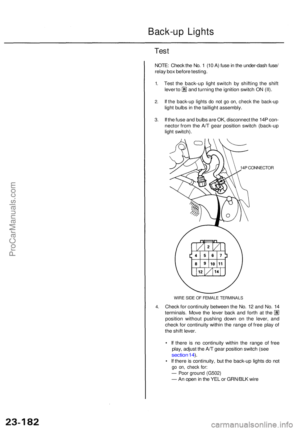
Tes t th e back-u p ligh t switc h b y shiftin g th e shif t
lever t o an d turnin g th e ignitio n switc h O N (II) .
If th e back-u p light s d o no t g o on , chec k th e back-u p
light bulb s i n th e tailligh t assembly .
I f th e fus e an d bulb s ar e OK , disconnec t th e 14 P con -
necto r fro m th e A/ T gea r positio n switc h (back-u p
ligh t switch) .
14P CONNECTO R
WIRE SID E O F FEMAL E TERMINAL S
Check fo r continuit y betwee n th e No . 1 2 an d No . 1 4
terminals . Mov e th e leve r bac k an d fort h a t th e
positio n withou t pushin g dow n o n th e lever , an d
chec k fo r continuit y withi n th e rang e o f fre e pla y o f
th e shif t lever .
• I f ther e i s n o continuit y withi n th e rang e o f fre e
play , adjus t th e A/ T gea r positio n switc h (se e
sectio n 14 ).
• I f ther e is continuity , bu t th e back-u p light s d o no t
go on , chec k for :
— Poo r groun d (G502 )
— An ope n in th e YE L o r GRN/BL K wir e
ProCarManuals.com
Page 1652 of 1771
Brake Light s an d Hig h Moun t Brak e Ligh t
Brake Switc h Tes t
1. I f on e o f th e brak e light s doe s no t g o on , chec k th e
bul b i n th e tailligh t o r th e hig h moun t brak e light .
2 . I f non e o f th e brak e light s g o on , chec k th e No . 3 0
(2 0 A ) fus e in th e under-hoo d fuse/rela y box .
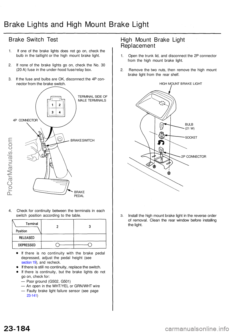
3 . I f th e fus e an d bulb s ar e OK , disconnec t th e 4 P con -
necto r fro m th e brak e switch .
4P CONNECTO R
TERMINAL SID E O FMAL E TERMINAL S
BRAK E SWITC H
BRAKEPEDAL
4. Chec k fo r continuit y betwee n th e terminal s i n eac h
switc h positio n accordin g t o th e table .
I f ther e i s n o continuit y wit h th e brak e peda l
depressed , adjus t th e peda l heigh t (se e
section 19 ), an d recheck .
If ther e is stil l n o continuity , replac e th e switch .
If ther e i s continuity , bu t th e brak e light s d o no t
g o on , chec k for :
— Poo r groun d (G502 , G501 )
— A n ope n i n th e WHT/YE L o r GRN/WH T wir e
— Fault y brak e ligh t failur e senso r (se e pag e
23-141 )
High Moun t Brak e Ligh t
Replacemen t
1. Ope n th e trun k lid , an d disconnec t th e 2 P connecto r
fro m th e hig h moun t brak e light .
2 . Remov e th e tw o nuts , the n remov e th e hig h moun t
brak e ligh t fro m th e rea r shelf .
HIGH MOUN T BRAK E LIGH T
BULB(21 W )
SOCKE T
2P CONNECTO R
3.Instal l th e hig h moun t brak e ligh t i n th e revers e orde r
of removal . Clea n th e rea r windo w befor e installin g
the light .
ProCarManuals.com
Page 1653 of 1771
Dash Lights Brightness Controller
Controller Input Test
NOTE: The control unit is built into the dash lights brightness controller.
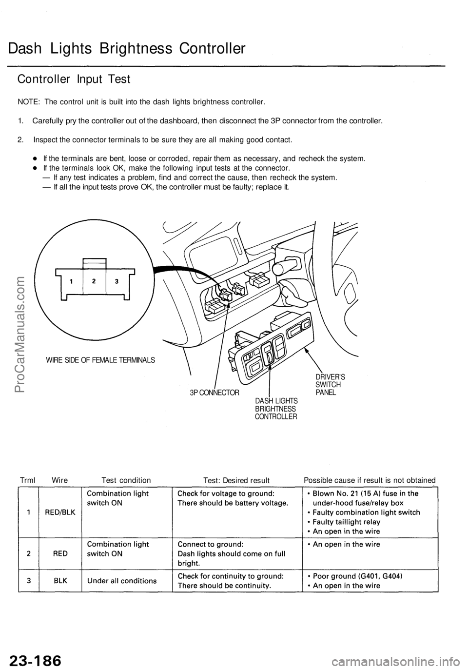
1. Carefully pry the controller out of the dashboard, then disconnect the 3P connector from the controller.
2. Inspect the connector terminals to be sure they are all making good contact.
If the terminals are bent, loose or corroded, repair them as necessary, and recheck the system.
If the terminals look OK, make the following input tests at the connector.
— If any test indicates a problem, find and correct the cause, then recheck the system.
— If all the input tests prove OK, the controller must be faulty; replace it.
WIRE SIDE OF FEMALE TERMINALS
3P CONNECTOR
DRIVER'S
SWITCH
PANEL
DASH LIGHTS
BRIGHTNESS
CONTROLLER
Trml Wire
Test condition
Test: Desired result
Possible cause if result is not obtainedProCarManuals.com
Page 1654 of 1771
Turn Signal/Hazar d Flashe r Syste m
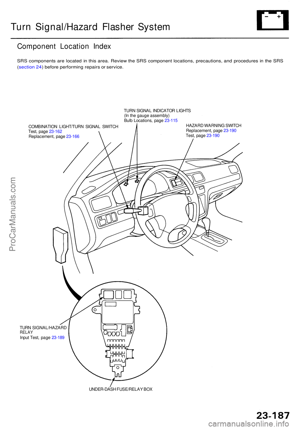
Componen t Locatio n Inde x
SRS component s ar e locate d i n thi s area . Revie w th e SR S componen t locations , precautions , an d procedure s i n th e SR S
( sectio n 24 ) befor e performin g repair s o r service .
COMBINATIO N LIGHT/TUR N SIGNA L SWITC H
Test , pag e 23-16 2
Replacement , pag e 23-16 6 TUR
N SIGNA L INDICATO R LIGHT S
(I n th e gaug e assembly )
Bul b Locations , pag e 23-11 5
HAZAR D WARNIN G SWITC H
Replacement , pag e 23-19 0
Test , pag e 23-19 0
TUR N SIGNAL/HAZAR D
RELAYInput Test , pag e 23-18 9
UNDER-DASH FUSE/RELA Y BO X
ProCarManuals.com
Page 1655 of 1771
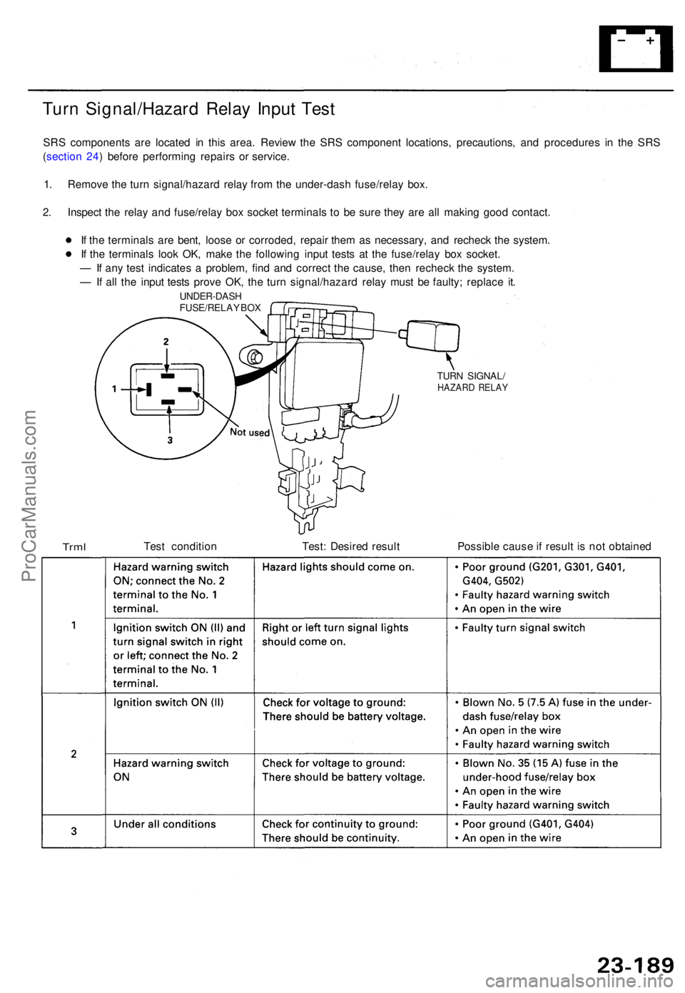
Turn Signal/Hazar d Rela y Inpu t Tes t
SRS component s ar e locate d i n thi s area . Revie w th e SR S componen t locations , precautions , an d procedure s i n th e SR S
( sectio n 24 ) befor e performin g repair s o r service .
1 . Remov e th e tur n signal/hazar d rela y fro m th e under-das h fuse/rela y box .
2 . Inspec t th e rela y an d fuse/rela y bo x socke t terminal s t o b e sur e the y ar e al l makin g goo d contact .
I f th e terminal s ar e bent , loos e o r corroded , repai r the m a s necessary , an d rechec k th e system .
I f th e terminal s loo k OK , mak e th e followin g inpu t test s a t th e fuse/rela y bo x socket .
— If an y tes t indicate s a problem , fin d an d correc t th e cause , the n rechec k th e system .
— If al l th e inpu t test s prov e OK , th e tur n signal/hazar d rela y mus t b e faulty ; replac e it .
UNDER-DAS H
FUSE/RELA Y BO X
TUR N SIGNAL /HAZARD RELA Y
TrmlTest conditio n Test: Desire d resul t Possible caus e if resul t i s no t obtaine d
ProCarManuals.com
Page 1656 of 1771
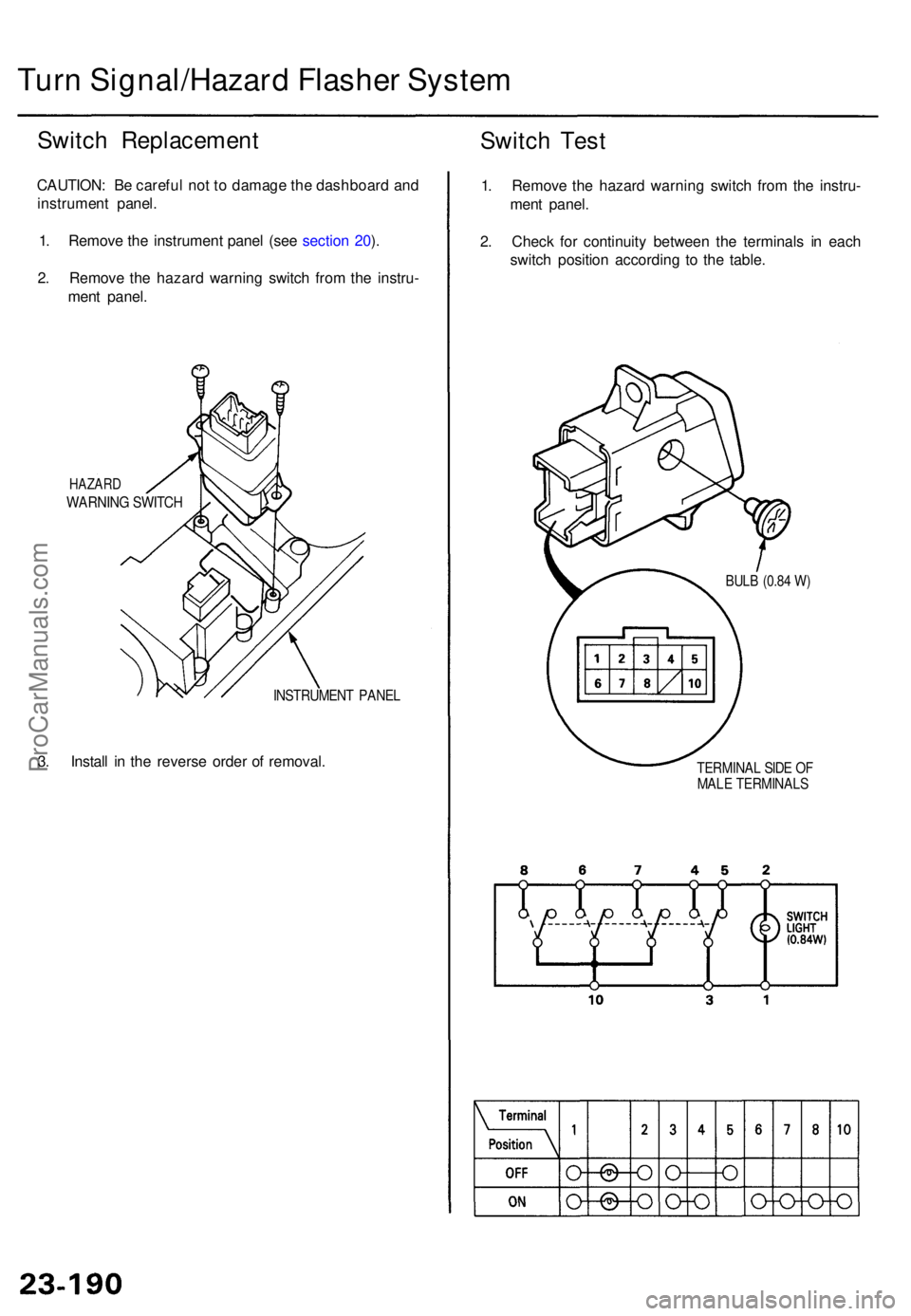
Turn Signal/Hazar d Flashe r Syste m
Switch Replacemen t
CAUTION: B e carefu l no t t o damag e th e dashboar d an d
instrumen t panel .
1 . Remov e th e instrumen t pane l (se e sectio n 20 ).
2 . Remov e th e hazar d warnin g switc h fro m th e instru -
men t panel .
HAZAR D
WARNIN G SWITC H
INSTRUMEN T PANE L
3. Instal l i n th e revers e orde r o f removal .
Switch Tes t
1. Remov e th e hazar d warnin g switc h fro m th e instru -
men t panel .
2 . Chec k fo r continuit y betwee n th e terminal s i n eac h
switc h positio n accordin g t o th e table .
BULB (0.8 4 W )
TERMINA L SID E O FMAL E TERMINAL S
ProCarManuals.com
Page 1657 of 1771
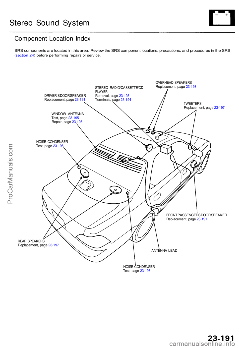
Stereo Soun d Syste m
Componen t Locatio n Inde x
SRS component s ar e locate d in thi s area . Revie w th e SR S componen t locations , precautions , an d procedure s in th e SR S
(sectio n 24 ) befor e performin g repair s o r service .
DRIVER' S DOO R SPEAKE R
Replacement , pag e 23-19 1
WINDO W ANTENN A
Test , pag e 23-19 5
Repair , pag e 23-19 5
NOIS E CONDENSE R
Test , pag e 23-19 6
STERE O RADIO/CASSETTE/C DPLAYERRemoval , pag e 23-19 3
Terminals , pag e 23-19 4
OVERHEA D SPEAKER SReplacement , pag e 23-19 8
REAR SPEAKER SReplacement , pag e 23-19 7
TWEETER SReplacement , pag e 23-19 7
FRON T PASSENGER S DOO R SPEAKE R
Replacement , pag e 23-19 1
ANTENN A LEA D
NOIS E CONDENSE R
Test , pag e 23-19 6
ProCarManuals.com
Page 1658 of 1771
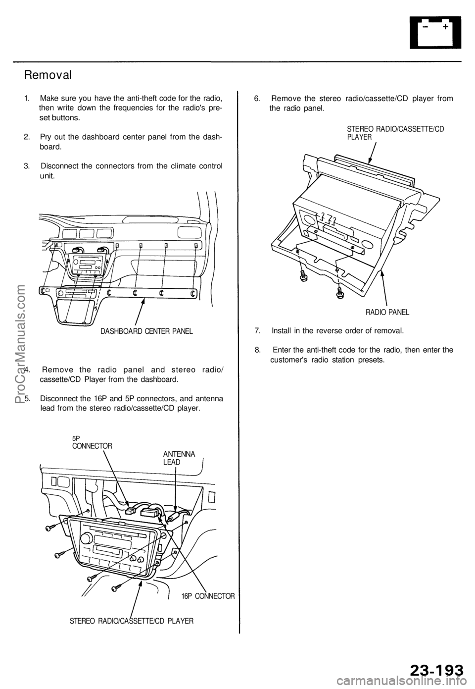
Removal
1. Mak e sur e yo u hav e th e anti-thef t cod e fo r th e radio ,
the n writ e dow n th e frequencie s fo r th e radio' s pre -
set buttons .
2. Pr y ou t th e dashboar d cente r pane l fro m th e dash -
board .
3 . Disconnec t th e connector s fro m th e climat e contro l
unit.
DASHBOAR D CENTE R PANE L
4. Remov e th e radi o pane l an d stere o radio /
cassette/C D Playe r fro m th e dashboard .
5 . Disconnec t th e 16 P an d 5 P connectors , an d antenn a
lea d fro m th e stere o radio/cassette/C D player .
5PCONNECTO RANTENNALEAD
16 P CONNECTO R
STERE O RADIO/CASSETTE/C D PLAYE R
6. Remov e th e stere o radio/cassette/C D playe r fro m
th e radi o panel .
STERE O RADIO/CASSETTE/C DPLAYER
RADIO PANE L
7. Instal l i n th e revers e orde r o f removal .
8 . Ente r th e anti-thef t cod e fo r th e radio , the n ente r th e
customer' s radi o statio n presets .
ProCarManuals.com
Page 1659 of 1771
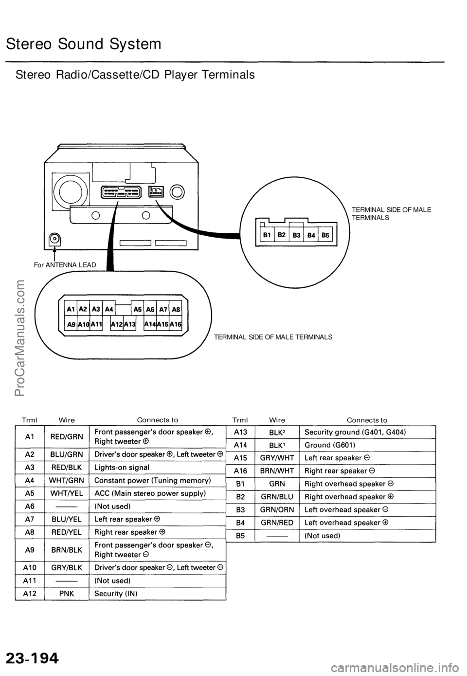
Stereo Soun d Syste m
Stereo Radio/Cassette/C D Playe r Terminal s
TERMINA L SID E O F MAL ETERMINAL S
For ANTENN A LEA D
TERMINAL SID E O F MAL E TERMINAL S
TrmlWireConnect s to
TrmlWireConnect s to
ProCarManuals.com
Page 1660 of 1771
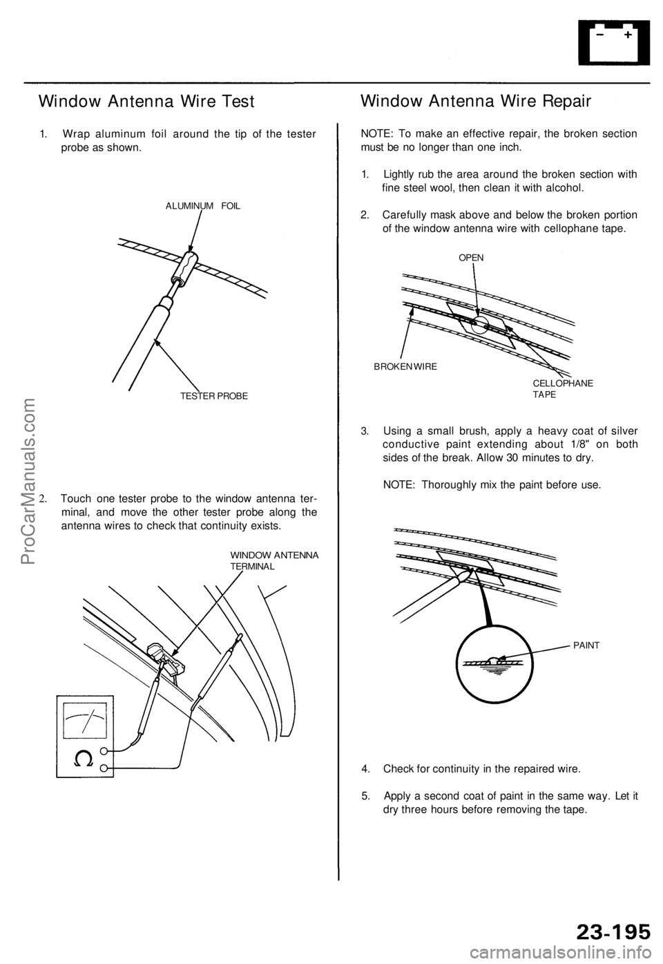
Window Antenn a Wir e Tes t
1. Wra p aluminu m foi l aroun d th e ti p of the teste r
prob e a s shown .
ALUMINU M FOI L
TESTE R PROB E
2.Touc h on e teste r prob e t o th e windo w antenn a ter -
minal , an d mov e th e othe r teste r prob e alon g th e
antenn a wire s t o chec k tha t continuit y exists .
WINDO W ANTENN ATERMINA L
Window Antenn a Wir e Repai r
NOTE: T o mak e a n effectiv e repair , th e broke n sectio n
mus t b e n o longe r tha n on e inch .
1 . Lightl y ru b th e are a aroun d th e broke n sectio n wit h
fin e stee l wool , the n clea n i t wit h alcohol .
2 . Carefull y mas k abov e an d belo w th e broke n portio n
o f th e windo w antenn a wir e wit h cellophan e tape .
OPEN
BROKE N WIR E
CELLOPHANE
TAPE
3.Usin g a smal l brush , appl y a heav y coa t of silve r
conductiv e pain t extendin g abou t 1/8 " o n bot h
side s o f th e break . Allo w 3 0 minute s t o dry .
NOTE : Thoroughl y mi x th e pain t befor e use .
PAIN T
4. Chec k fo r continuit y i n th e repaire d wire .
5 . Appl y a secon d coa t o f pain t i n th e sam e way . Le t i t
dr y thre e hour s befor e removin g th e tape .
ProCarManuals.com