engine ACURA TL 1995 Service Workshop Manual
[x] Cancel search | Manufacturer: ACURA, Model Year: 1995, Model line: TL, Model: ACURA TL 1995Pages: 1771, PDF Size: 62.49 MB
Page 130 of 1771
Oil Pressur e Engin
e Oi l Temperatur e Switc h
Testin gTestin g
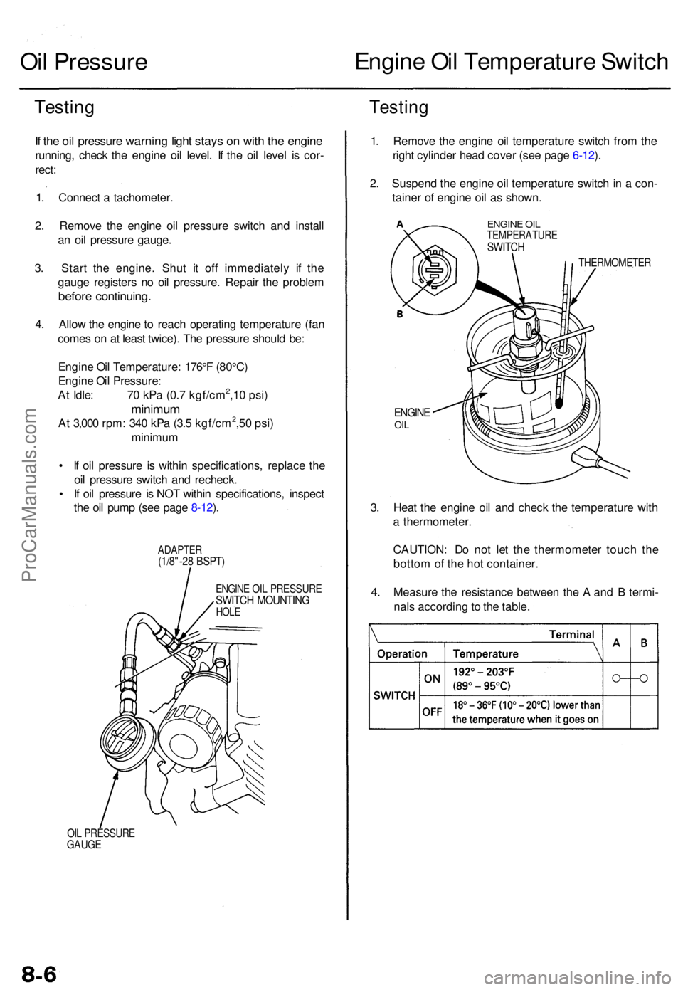
If th e oi l pressur e warnin g ligh t stay s o n wit h th e engin e
running , chec k th e engin e oi l level . I f th e oi l leve l i s cor -
rect :
1 . Connec t a tachometer .
2 . Remov e th e engin e oi l pressur e switc h an d instal l
a n oi l pressur e gauge .
3 . Star t th e engine . Shu t i t of f immediatel y i f th e
gaug e register s n o oi l pressure . Repai r th e proble m
before continuing .
4. Allo w th e engin e to reac h operatin g temperatur e (fa n
come s o n a t leas t twice) . Th e pressur e shoul d be :
Engin e Oi l Temperature : 176° F (80°C )
Engin e Oi l Pressure :
A t Idle : 7 0 kP a (0. 7 kgf/cm
2,1 0 psi )
minimu m
At 3,00 0 rpm : 34 0 kP a (3. 5 kgf/cm2,5 0 psi )
minimu m
• I f oi l pressur e i s withi n specifications , replac e th e
oi l pressur e switc h an d recheck .
• I f oi l pressur e i s NO T withi n specifications , inspec t
th e oi l pum p (se e pag e 8-12 ).
ADAPTE R(1/8"-28 BSPT )
ENGIN E OI L PRESSUR ESWITCH MOUNTIN GHOLE
OIL PRESSUR E
GAUG E
1. Remov e th e engin e oi l temperatur e switc h fro m th e
righ t cylinde r hea d cove r (se e pag e 6-12 ).
2 . Suspen d th e engin e oi l temperatur e switc h in a con -
taine r o f engin e oi l a s shown .
ENGINE OI LTEMPERATUR ESWITCH
THERMOMETE R
ENGINEOIL
3. Hea t th e engin e oi l an d chec k th e temperatur e wit h
a thermometer .
CAUTION : D o no t le t th e thermomete r touc h th e
botto m of th e ho t container .
4 . Measur e th e resistanc e betwee n th e A an d B termi -
nal s accordin g to th e table .
ProCarManuals.com
Page 141 of 1771
Radiator
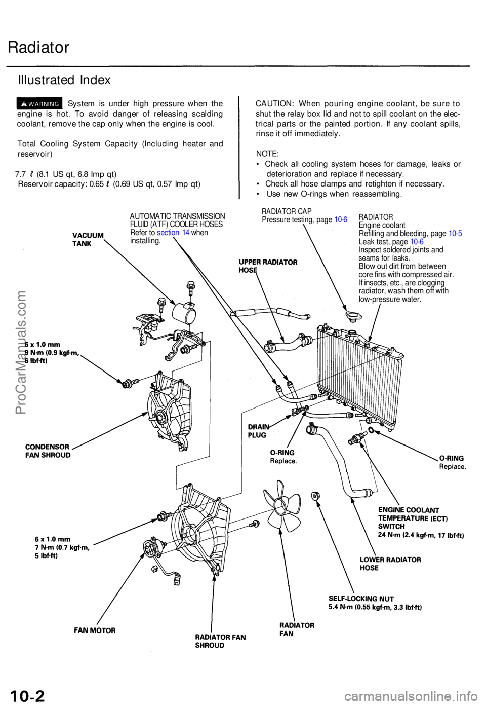
Illustrate d Inde x
Syste m is unde r hig h pressur e whe n th e
engin e i s hot . T o avoi d dange r o f releasin g scaldin g
coolant , remov e th e ca p onl y whe n th e engin e is cool .
Tota l Coolin g Syste m Capacit y (Includin g heate r an d
reservoir )
7.7 (8. 1 US qt , 6. 8 Im p qt )
Reservoi r capacity : 0.6 5 (0.6 9 U S qt , 0.5 7 Im p qt ) CAUTION
: Whe n pourin g engin e coolant , b e sur e t o
shu t th e rela y bo x li d an d no t t o spil l coolan t o n th e elec -
trica l part s o r th e painte d portion . I f an y coolan t spills ,
rins e it of f immediately .
NOTE:
• Chec k al l coolin g syste m hose s fo r damage , leak s o r
deterioratio n an d replac e if necessary .
• Chec k al l hos e clamp s an d retighte n if necessary .
• Us e ne w O-ring s whe n reassembling .
RADIATOR CA PPressur e testing , pag e 10- 6RADIATO REngine coolan t
Refillin g an d bleeding , pag e 10- 5
Leak test , pag e 10- 6Inspec t soldere d joint s an dseam s fo r leaks .Blow ou t dir t fro m betwee ncore fin s wit h compresse d air .If insects , etc. , ar e cloggin gradiator , was h the m of f wit hlow-pressur e water .
AUTOMATI C TRANSMISSIO NFLUID (ATF ) COOLE R HOSE SRefer t o sectio n 1 4 whe ninstalling .
ProCarManuals.com
Page 142 of 1771
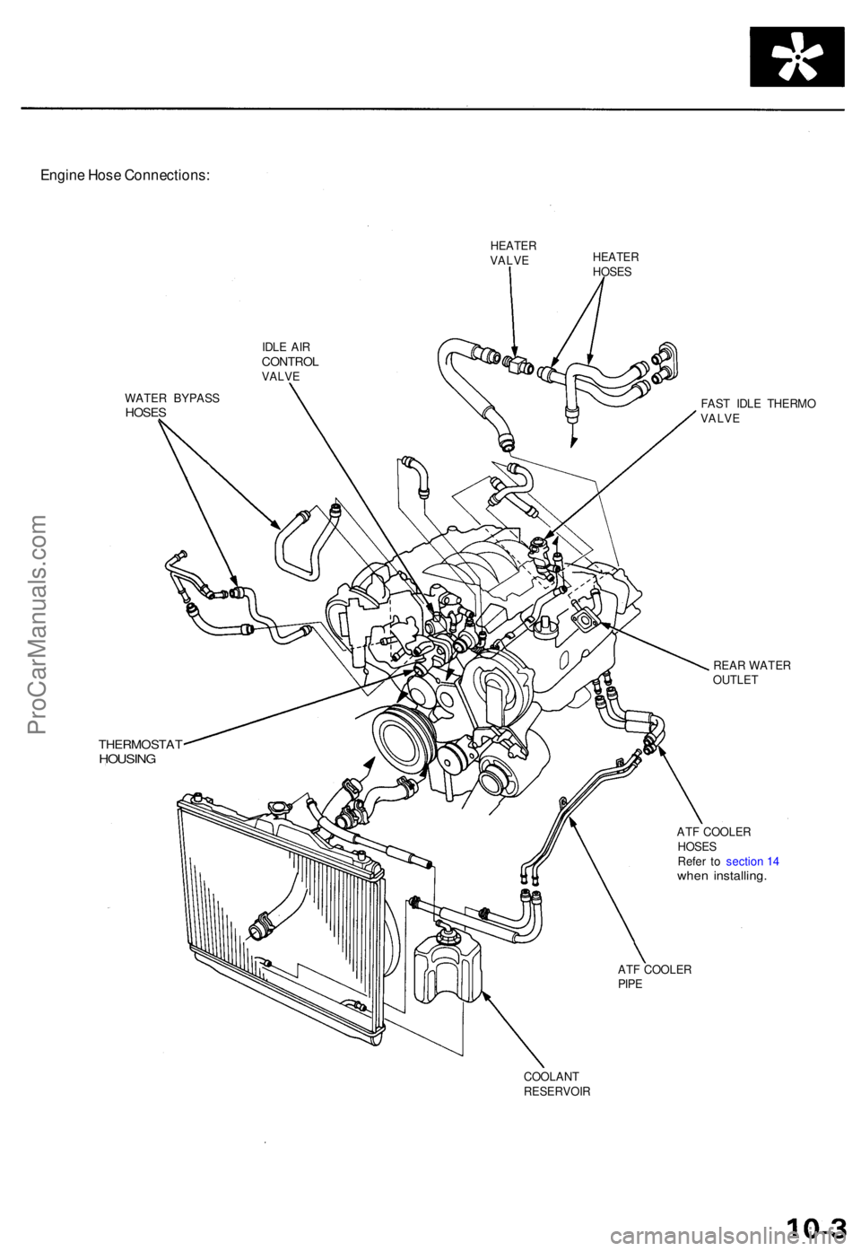
Engine Hos e Connections :
HEATERVALVEHEATE RHOSES
IDL E AI R
CONTRO LVALVE
WATE R BYPAS S
HOSES
THERMOSTA THOUSING
FAST IDL E THERM O
VALV E
REA R WATE R
OUTLE T
AT F COOLE R
HOSE S
Refe r t o sectio n 1 4
whe n installing .
ATF COOLE R
PIP E
COOLAN T
RESERVOI R
ProCarManuals.com
Page 144 of 1771
Engine Coolan t Refillin g an d Bleedin g
CAUTION : Whe n pourin g engin e coolant , b e sur e t o
shu t th e rela y bo x li d an d no t t o le t coolan t spil l o n th e
electrica l part s o r th e paint . I f an y coolan t spills , rins e it
of f immediately .
NOTE:
Perfor m thi s procedur e whe n th e engin e is cool .
Befor e replacin g th e coolant , tur n th e ignitio n O N (II) ,
slowl y tur n th e climat e contro l temperatur e kno b t o
90 ° an d tur n of f th e ignition . Thi s wil l allo w th e
coolan t i n th e heate r t o drai n ou t wit h th e res t o f th e
system .
1 . Mak e sur e yo u hav e th e anti-thef t cod e fo r th e radio ,
the n writ e dow n th e frequencie s fo r th e radio' s pre -
se t buttons .
2 . Disconnec t th e batter y negativ e termina l first , the n
th e positiv e terminal , the n remov e th e batter y an d
batter y bas e (se e pag e 5-4 ).
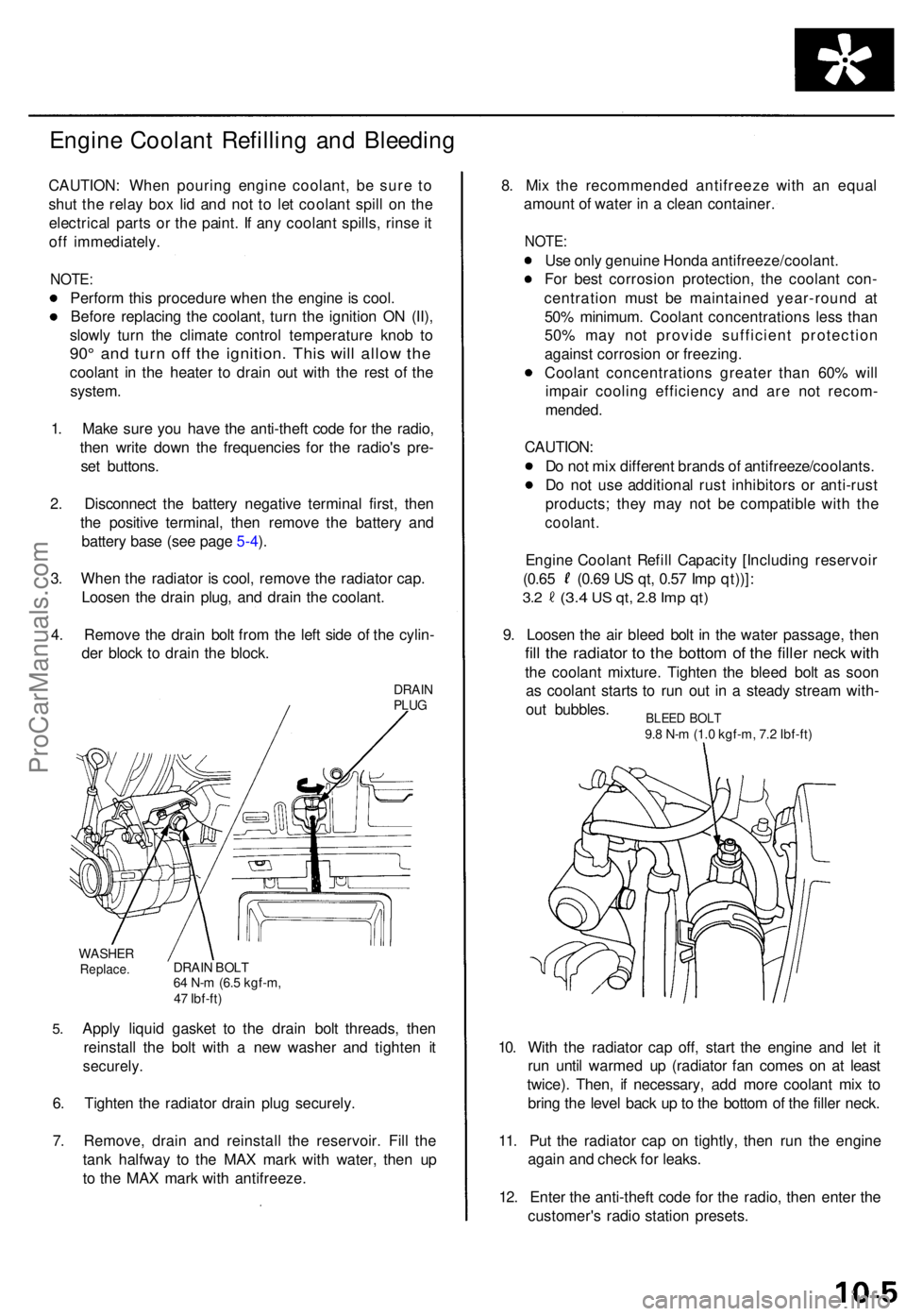
3 . Whe n th e radiato r i s cool , remov e th e radiato r cap .
Loose n th e drai n plug , an d drai n th e coolant .
4 . Remov e th e drai n bol t fro m th e lef t sid e o f th e cylin -
de r bloc k t o drai n th e block .
DRAINPLUG
5.
WASHE RReplace .DRAIN BOL T64 N- m (6. 5 kgf-m ,
4 7 Ibf-ft )
Apply liqui d gaske t t o th e drai n bol t threads , the n
reinstal l th e bol t wit h a ne w washe r an d tighte n i t
securely .
6. Tighte n th e radiato r drai n plu g securely .
7 . Remove , drai n an d reinstal l th e reservoir . Fil l th e
tan k halfwa y t o th e MA X mar k wit h water , the n u p
t o th e MA X mar k wit h antifreeze . 8
. Mi x th e recommende d antifreez e wit h a n equa l
amoun t o f wate r i n a clea n container .
NOTE:
Use onl y genuin e Hond a antifreeze/coolant .
Fo r bes t corrosio n protection , th e coolan t con -
centratio n mus t b e maintaine d year-roun d a t
50 % minimum . Coolan t concentration s les s tha n
50 % ma y no t provid e sufficien t protectio n
agains t corrosio n o r freezing .
Coolan t concentration s greate r tha n 60 % wil l
impai r coolin g efficienc y an d ar e no t recom -
mended .
CAUTION :
D o no t mi x differen t brand s o f antifreeze/coolants .
D o no t us e additiona l rus t inhibitor s o r anti-rus t
products ; the y ma y no t b e compatibl e wit h th e
coolant .
Engine Coolan t Refil l Capacit y [Includin g reservoi r
(0.65 (0.6 9 U S qt , 0.5 7 Im p qt))] :
3.2 (3. 4 US qt , 2. 8 Im p qt )
9. Loose n th e ai r blee d bol t i n th e wate r passage , the n
fill th e radiato r t o th e botto m o f th e fille r nec k wit h
the coolan t mixture . Tighte n th e blee d bol t a s soo n
a s coolan t start s t o ru n ou t i n a stead y strea m with -
ou t bubbles .
10 . Wit h th e radiato r ca p off , star t th e engin e an d le t i t
ru n unti l warme d u p (radiato r fa n come s o n a t leas t
twice) . Then , i f necessary , ad d mor e coolan t mi x t o
brin g th e leve l bac k u p to th e botto m o f th e fille r neck .
11 . Pu t th e radiato r cap on tightly , the n ru n th e engin e
agai n an d chec k fo r leaks .
12 . Ente r th e anti-thef t cod e fo r th e radio , the n ente r th e
customer' s radi o statio n presets .
BLEED BOL T9.8 N- m (1. 0 kgf-m , 7. 2 Ibf-ft )
ProCarManuals.com
Page 145 of 1771
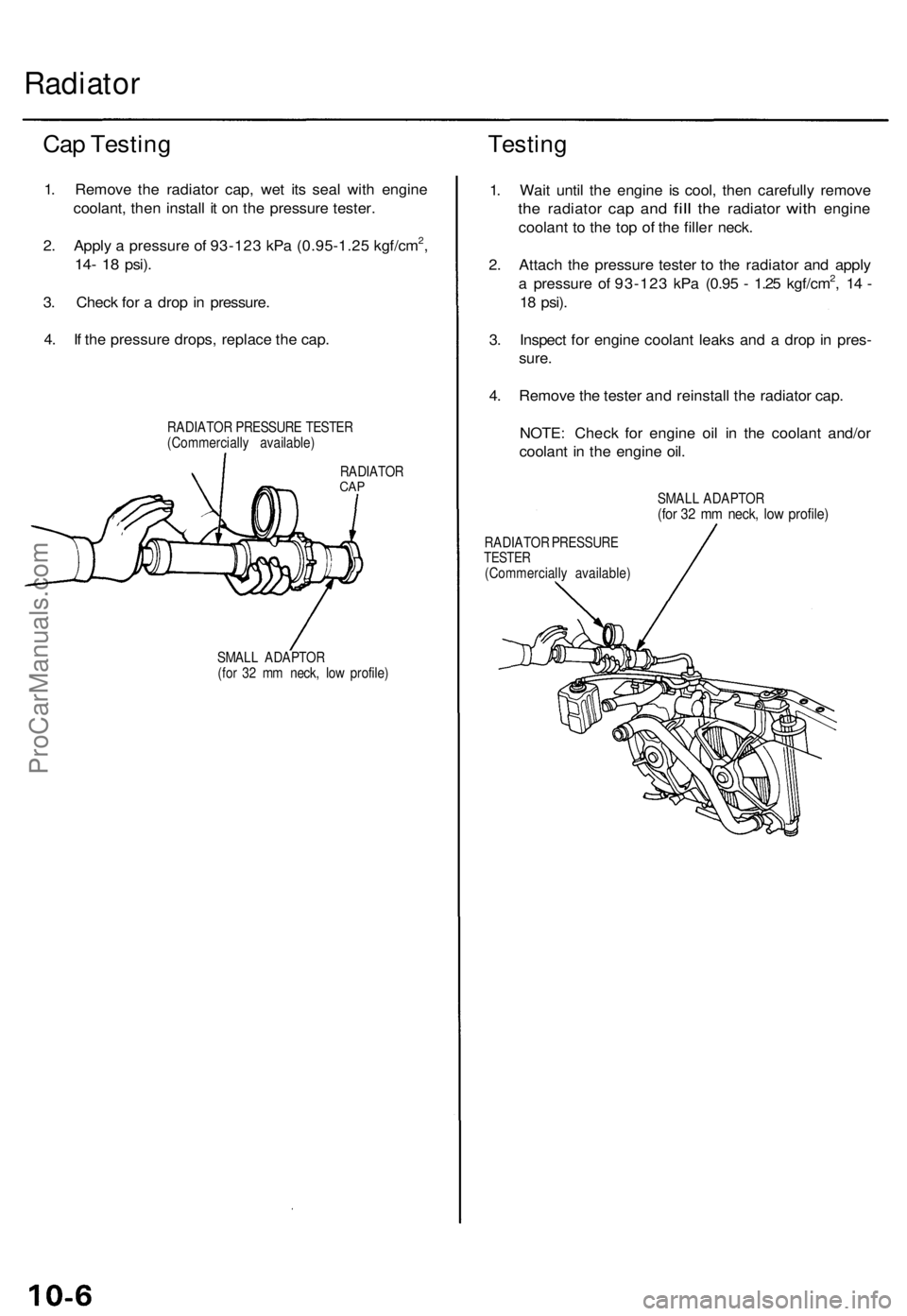
Radiator
Cap Testing
1. Remove the radiator cap, wet its seal with engine
coolant, then install it on the pressure tester.
2. Apply a pressure of 93-123 kPa (0.95-1.25 kgf/cm2,
14- 18
psi).
3. Check for a drop in pressure.
4. If the pressure drops, replace the cap.
RADIATOR PRESSURE TESTER
(Commercially available)
Testing
RADIATOR
CAP
SMALL ADAPTOR
(for 32 mm neck, low profile)
1. Wait until the engine is cool, then carefully remove
the
radiator
cap and
fill
the
radiator
with
engine
coolant to the top of the filler neck.
2. Attach the pressure tester to the radiator and apply
a pressure of 93-123 kPa (0.95 - 1.25 kgf/cm2, 14 -
18
psi).
3. Inspect for engine coolant leaks and a drop in pres-
sure.
4. Remove the tester and reinstall the radiator cap.
NOTE: Check for engine oil in the coolant and/or
coolant in the engine oil.
SMALL ADAPTOR
(for 32 mm neck, low profile)
RADIATOR PRESSURE
TESTER
(Commercially available)ProCarManuals.com
Page 146 of 1771
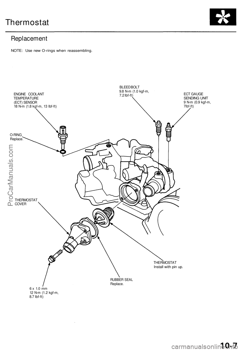
Thermostat
Replacement
NOTE: Use new O-rings when reassembling.
ENGINE COOLANT
TEMPERATURE
(ECT) SENSOR
18 N-m (1.8 kgf-m, 13 Ibf-ft)
BLEED BOLT
9.8 N-m (1.0 kgf-m,
7.2 Ibf-ft)
O-RING
Replace.
ECT GAUGE
SENDING UNIT
9 N-m (0.9 kgf-m,
7lbf-ft)
THERMOSTAT
COVER
THERMOSTAT
Install with pin up.
RUBBER SEAL
Replace.
6 x 1.0 mm
12 N-m (1.2 kgf-m,
8.7 Ibf-ft)ProCarManuals.com
Page 170 of 1771
![ACURA TL 1995 Service Workshop Manual System Descriptio n
System Connector s [Engin e Compartment ]
ENGINEWIREHARNES S
C106 C13
8
MAIN WIR EHARNES S
C127
C132
C131
C113 C130
C137
C136
C110
C107
C108
C11 1
C114
C109
ProCarManuals.co ACURA TL 1995 Service Workshop Manual System Descriptio n
System Connector s [Engin e Compartment ]
ENGINEWIREHARNES S
C106 C13
8
MAIN WIR EHARNES S
C127
C132
C131
C113 C130
C137
C136
C110
C107
C108
C11 1
C114
C109
ProCarManuals.co](/img/32/56993/w960_56993-169.png)
System Descriptio n
System Connector s [Engin e Compartment ]
ENGINEWIREHARNES S
C106 C13
8
MAIN WIR EHARNES S
C127
C132
C131
C113 C130
C137
C136
C110
C107
C108
C11 1
C114
C109
ProCarManuals.com
Page 174 of 1771
![ACURA TL 1995 Service Workshop Manual
System Description
System Connectors [Engine Compartment] (cont'd)
C173
C139
C120/
C171
C141
C119
C118
C116
ENGINE
WIRE
HARNESS
G101
C308
C311
MAIN WIRE
HARNESS
C172
C152/
C33 ACURA TL 1995 Service Workshop Manual
System Description
System Connectors [Engine Compartment] (cont'd)
C173
C139
C120/
C171
C141
C119
C118
C116
ENGINE
WIRE
HARNESS
G101
C308
C311
MAIN WIRE
HARNESS
C172
C152/
C33](/img/32/56993/w960_56993-173.png)
System Description
System Connectors [Engine Compartment] (cont'd)
C173
C139
C120/
C171
C141
C119
C118
C116
ENGINE
WIRE
HARNESS
G101
C308
C311
MAIN WIRE
HARNESS
C172
C152/
C332
C157
C338'2
C337'2
C333'1
C329
C320*1
C328
C324
C339*2
C123 C129
*1:'96 model
*2: '97 - 98 models
C126/
C322
C125
C135
C174*2
C140ProCarManuals.com
Page 183 of 1771
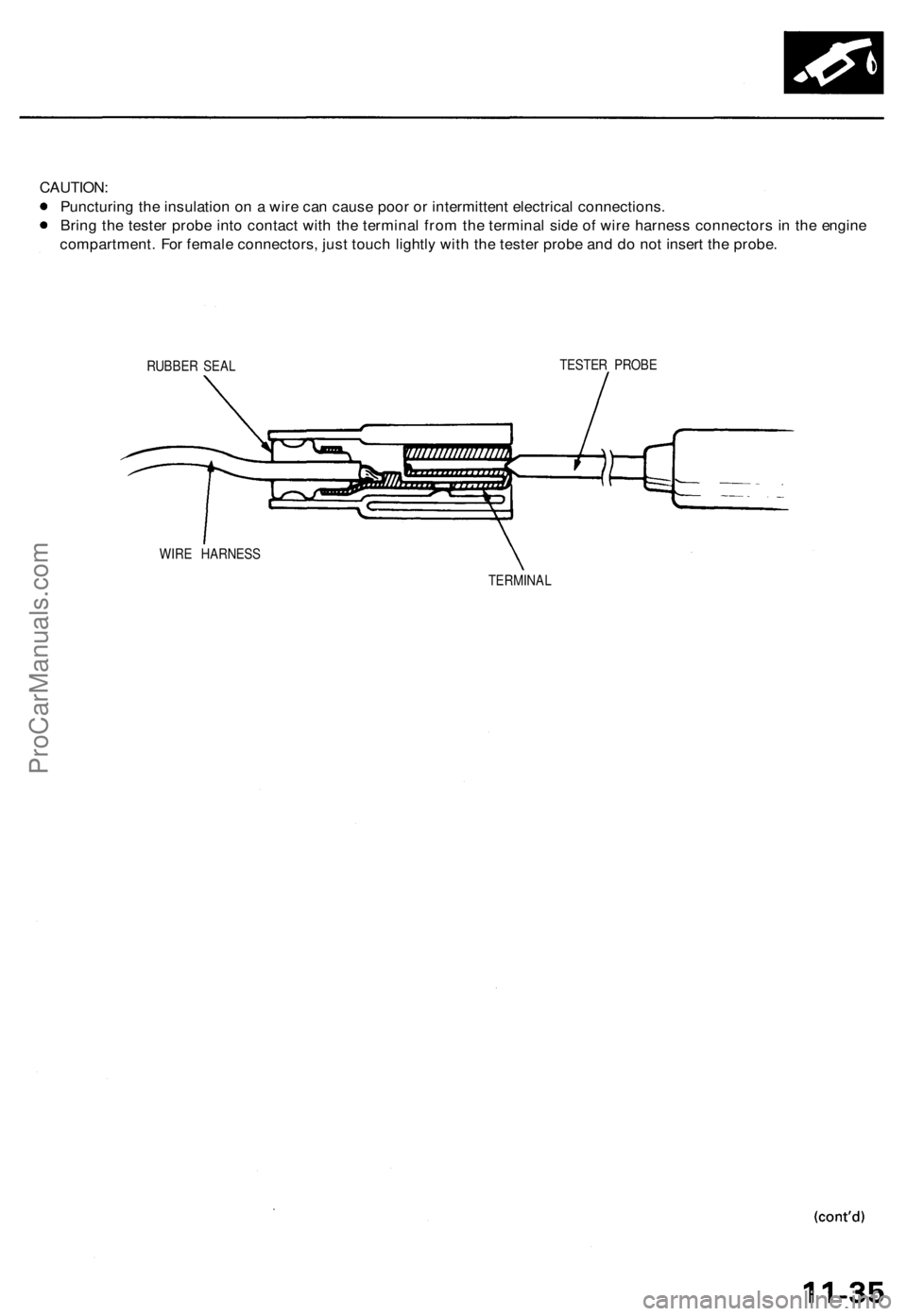
CAUTION:
Puncturing the insulation on a wire can cause poor or intermittent electrical connections.
Bring the tester probe into contact with the terminal from the terminal side of wire harness connectors in the engine
compartment. For female connectors, just touch lightly with the tester probe and do not insert the probe.
RUBBER SEAL
TESTER PROBE
WIRE HARNESS
TERMINALProCarManuals.com
Page 185 of 1771
Powertrain Contro l Modul e Dat a
B y connectin g th e OB D II sca n too l o r th e Hond a PG M Teste r t o th e 16 P dat a lin k connecto r (DLC) , variou s dat a ca n b e
retrieve d fro m th e PCM . Th e item s liste d in th e tabl e belo w confor m to th e SA E recommende d practice .
Th e Hond a PG M Teste r als o read s dat a beyon d tha t recommende d b y SAE .
Understandin g thi s dat a wil l hel p t o fin d th e cause s o f intermitten t failure s o r engin e problems .
NOTE:
The "operatin g values " give n belo w ar e approximat e value s an d ma y b e differen t dependin g o n th e environmen t an d
the individua l car .
Unles s note d otherwise , "a t idl e speed " mean s idlin g wit h th e engine completel y warme d up , transmissio n i n o r
position , an d th e A/ C an d al l accessorie s turne d off .
Dat aDescriptio nOperating Valu e
Freeze Dat a
Diagnosti c
Troubl e Cod e
(DTC )
If th e PC M detect s a problem , i t wil l stor e it a s a cod e
consistin g o f on e lette r an d fou r numbers .
Dependin g o n th e problem , a n SAE-define d cod e
(P0xxx ) o r a Honda-define d cod e (P1xxx ) wil l b e outpu t
t o th e tester . I
f n o proble m is detected ,
ther e i s n o output .
Engin e Spee d Th
e PC M compute s engin e spee d fro m th e signal s sen t
fro m th e Crankshaf t Positio n sensor .
Thi s dat a is use d fo r determinin g th e tim e an d amoun t
o f fue l injection . Nearl
y th e sam e a s
tachomete r indicatio n a t
idl e speed :
640 5 0 rp m
Vehicl e Spee d Th
e PC M convert s puls e signal s fro m th e Vehicl e
Spee d Senso r (VSS ) int o spee d data . Nearl
y th e sam e a s
speedomete r indicatio n
Manifol d
Absolut e
Pressur e (MAP )
The absolut e pressur e create d in th e intak e manifol d b y
engin e loa d an d speed . Wit
h engin e stopped :
Nearl y th e sam e a s atmo -
spheri c pressur e a t idl e
speed :
24-37 kP a (180-28 0
mmHg, 7.1-11. 0 inHg )
Engin e Coolan t
Temperatur e
(ECT)
The EC T senso r convert s coolan t temperatur e int o
voltag e an d signal s th e PCM . Th e senso r i s a thermisto r
whos e interna l resistanc e change s wit h coolan t
temperature . Th e PC M use s th e voltag e signal s fro m
th e EC T senso r t o determin e th e amoun t o f injecte d
fuel . Wit
h col d engine :
Sam e a s ambien t temper -
atur e an d IA T
Wit h engin e warme d up :
approx . 158-212° F
(70-100°C )
Heate d Oxyge n
Senso r (H02S )
(Bank 1, Sensor 1)
(Ban k 2 , Senso r 1 )
(Senso r 2 )
Th e Heate d Oxyge n Senso r detect s th e oxyge n conten t
i n th e exhaus t ga s an d send s voltag e signal s to th e
PCM . Base d o n thes e signals , th e PC M control s th e
air/fue l ratio . Whe n th e oxyge n conten t i s hig h (tha t is ,
whe n th e rati o is leane r tha n th e stoichiometri c ratio) ,
th e voltag e signa l i s lower . Whe n th e oxyge n conten t i s
lo w (tha t is , whe n th e rati o is riche r tha n th e stoichio -
metric ratio) , th e voltag e signa l i s higher .
0.0-1.2 5 V
A t idl e speed :
about 0.1-0. 9 V
O
(Senso r 1 )
ProCarManuals.com