ECU ASTON MARTIN DB7 1997 Repair Manual
[x] Cancel search | Manufacturer: ASTON MARTIN, Model Year: 1997, Model line: DB7, Model: ASTON MARTIN DB7 1997Pages: 421, PDF Size: 9.31 MB
Page 228 of 421
Electrics
Seat Control Module Removal/Replacement 97.5 MY 'O "3^2?
Switch on the ignition and checi< that the airbag
warning lamp comes on when the ignition is
switched on and extinguishes after approximately
six seconds indicating satisfactory completion of
the pretensioner and airbag system self
tests.
Fit
the front
seat
retaining screws ensuring
a
1.2mm
gap between the screw heads
and
the
slides.
Power
the seat forward and refit the rear screws.
Caution:
Centralise the
rear
fixing holes
with the
body weld
nuts
prior to
inserting the
bolts.
Torque the rear screws to 25 Nm. Power the seat
backwards. Torque the front screws to 25 Nm.
Motor the seat through its full range of movement
to ensure correct
operation.
6.6.08
Seat Control Module 97.5 MY
Removal
WARNING -
Seat
belt
Pretensioners
(if
fitted):
To avoid the possibility
of
personal injury caused
by accidental deployment of the seat belt
pretensioner,
disconnect
the
vehicle battery and
wait at
least
10
minutes
for all
voltages
to fully
discharge
before
working
near the
pretensioner
system.
This covers
the
possibility
of
the
normal
capacitor
discharge circuits
being
inoperative and
failing to discharge the detonator capacitor when
instructed
to
do
so.
1.
Lower the door window and open the relevant
door. Disconnect
the
battery ground cableand wait
for 10 minutes if
a
pretensioner
is
fitted.
Otherwise,
proceed immediately to step 2.
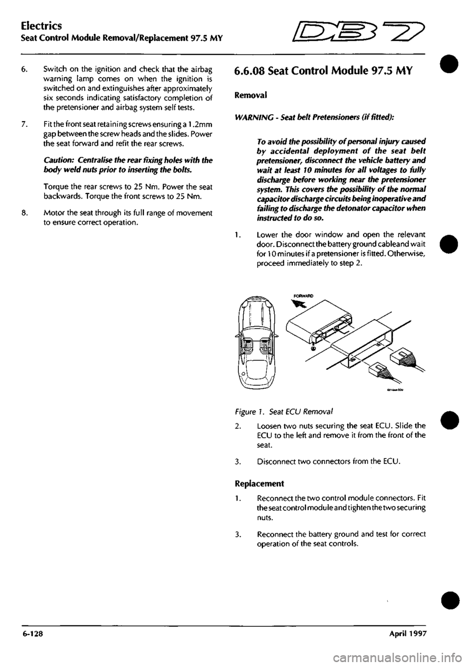
(ei-SMiECu
Figure!.
Seat ECU Removal
2. Loosen two nuts securing the seat ECU. Slide the
ECU to the left and remove it from the front of the
seat.
3. Disconnect two connectors from the ECU.
Replacement
1.
Reconnect the two control module connectors. Fit
the seat control
moduleand
tighten
thetwo securing
nuts.
3. Reconnect the battery ground and test for correct
operation of the seat controls.
6-128 April 1997
Page 229 of 421
O" D^?
Body and Trim
Contents
Contents
Body and Trim
Body Repair
Potential Risks
Precautions
General Repair Notes
Steel Body Parts - Repair, Remove and Replace
RTM Body Parts
Body Panel and Trim Removal
Front Apron
Front Undertray
Wheel Arch Liners
Side Sills (top fixings)
Side Sills (bottom fixings)
Rear Bumper
Doors
Door Liners
Door Liner (components)
Steering Wheel
Column Switches
Instrument Panel (surround)
Instrument Panel
Facia Underscuttles
Glove Box
Facia Mountings (1)
Facia Mountings (2)
Console Instruments
Radio
Front Seats
Ashtray
Centre Console
Seat ECU Covers
Rear Console
Rear Seats and C Post Trim
Quarter Panels, B Post Panels, Parcel Shelf
Headlining
Roof System Description and Repair Procedures
Vol ante Roof
Roof and Rear Quarter Light Control
Roof Component Location
Roof Control System
9.0.02.1
Roof Removal/Replacement
9.0.02.3
Roof Hydrailic Control System
9.0.02.5
Bleeding the Roof Hydraulic System
9.1.01.1
Rear Quarter Window Renewal
9.1.01.2
Rear Quarter Glass Adjustment
9.1.01.4
Rear Quarter Window Lift Motor - LH
9.1.01.5
Rear Quarter Window Lift Motor - RH
Roof Sealing and Wind Noise
9.2.01.5
'A' Post/Header Sealing and Lock Adj
9.2.01.6
Roof Seals - Adjustment
9.2.01.7
Cheater Plate Seals - Adjust/Renew
9.2.01.8
Door Glass Adjustment
Alcantara Cleaning
7-1
7-2
7-2
7-3
7-3
7-4
7-5
7-6
Sheet 1
Sheet 2
Sheet 3
Sheet 4
Sheet 5
Sheet 6
Sheet 7
Sheet 8
Sheet 9
Sheet 10
Sheet 11
Sheet 12
Sheet 13
Sheet 14
Sheet 15
Sheet 16
Sheet 17
Sheet 18
Sheet 19
Sheet 20
Sheet 21
Sheet 22
Sheet 23
Sheet 24
Sheet 25
Sheet 26
Sheet 27
7-7
7-7
7-8
7-9
7-10
7-11
7-12
7-13
7-14
7-15
7-16
7-17
7-17
7-18
7-19
7-20
7-21
May 1996 7-1
Page 233 of 421

'^?
Body and Trim
Body Repair - RTM Body Panels
RTM Body Parts
Certain exterior panels of the vehicle are
manufactured from RTM as shown as shaded areas
in Figure 1. The Front and rear bumpers are made
from
R-RIM
Repair Procedures
Cosmetic Damage
Repair the paintwork using standard procedures.
Substrate surface
Where the defect does not affect the physical
strength of the panel, fill and repaint using standard
techniques.
Substrate Penetration
No reliable repair procedures are possible to correct
major physical damage to RTM panels. Any small
defect which do not affect the intgrity or security of
the panel may be filled and repainted at the owners
risk.
Uote: Becauseof the inherent flexibility of plastic panels,
hard filler may
crack.
Such repairs cannot
therefore
be
guaranteed.
Where the damage affects the security and or the
integrity of the panel, it must be replaced.
Precautions during Paint Operations
When any repair operation is being completed on
the DB7 paintwork, take particular care to protect
the leather upholstery and trim from paint
contamination.
Figure 1.
Damage Recognition
Before any remedial action is carried out the
damaged should be
assessed.
If the cover has been
holed or torn it must be replaced. Repair should be
attempted only if the damage falls into one of the
following three categories.
Cosmetic
Substrate surface
Substrate
penetration
Abrasion to the surface paint
finish
Deep scratches, gouges or
localised radial stress cracks.
Splits not exceeding 100 mm.
Splits radiating from a gouge
and accompanied by localised
stress cracks.
May 1996 7-5
Page 234 of 421
Body and Trim
Body Panel and Trim Removal 5^7
Body Panel and Trim Removal
The following diagrams show the fixings for all
removeable body and trim panels.
Sheet 1. Front Apron
Sheet 2. Front Undertray
Sheet 3. Wheel Arch Liners
Sheet 4. Side Sills (top fixings)
Sheets. Side Sills (bottom fixings)
Sheet 6. Rear Bumper
Sheet 7. Doors
Sheet 8. Door Liners
Sheet 9. Door Liner (components)
Sheet 10. Steering Wheel
Sheet 11. Column Switches
Sheet 12. Instrument Panel (surround)
Sheet 13. Instrument Panel
Sheet 14. Facia Underscuttles
Sheet 15. Glove Box
Sheet 16. Facia Mountings (1)
Sheet
1
7. Facia Mountings (2)
Sheet 18. Console Instruments
Sheet 19. Radio
Sheet 20. Front Seats
Sheet
21.
Ashtray
Sheet 22. Centre Console
Sheet 23. Seat ECU Covers
Sheet 24. Rear Console
Sheet 25. Rear Seats and C Post Trim
Sheet 26. Quarter Panels, B Post Panels, Parcel Shelf
Sheet 27. Headlining
7-6 May 1996
Page 265 of 421
Body and Trim
Roof Removal/Replacement [D::M^=2?
9.0.02.1 - Roof Removal/Replacement
1.
2.
3.
4.
5.
6.
7.
8.
Move the front seats fully forward for access.
Remove the rear seat squab and cushion. Remove
the rear quarter trim panel.
Release the roof side curtain clips.
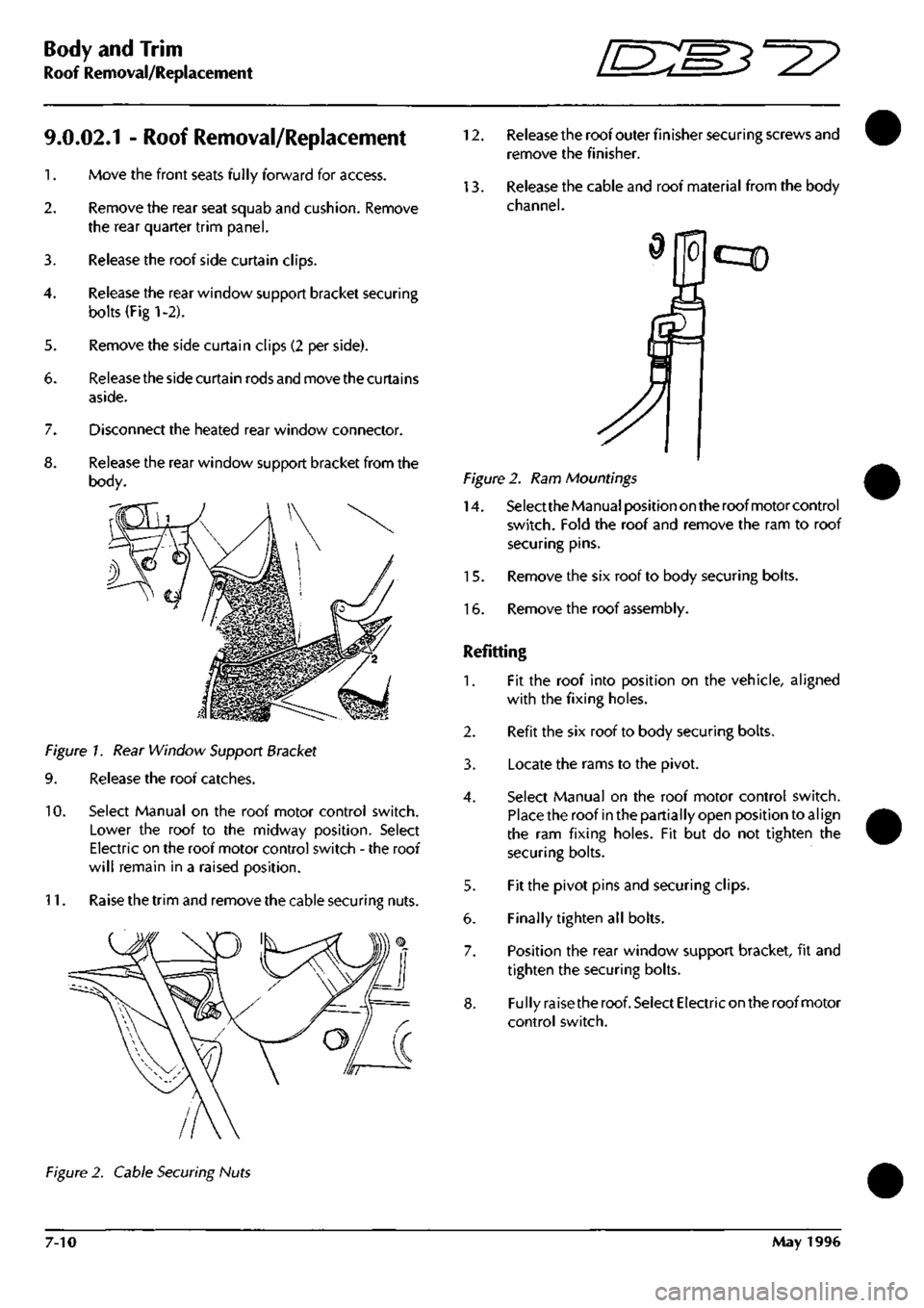
Release the rear window support bracket securing
bolts (Fig 1-2).
Remove the side curtain clips (2 per side).
Release the side curtain rods and move the curtains
aside.
Disconnect the heated rear window connector.
Release the rear window support bracket from the
body.
Figure 1. Rear Window Support Bracket
9. Release the roof catches.
10.
Select Manual on the roof motor control switch.
Lower the roof to the midway position. Select
Electric on the roof motor control switch - the roof
will remain in a raised position.
11.
Raise the trim and remove the cable securing nuts.
12.
Release the roof outer finisher securing screws and
remove the finisher.
13.
Release the cable and roof material from the body
channel.
cqD
Figure 2. Ram Mountings
14.
Select the Manual position on the roof motor control
switch.
Fold the roof and remove the ram to roof
securing pins.
15.
Remove the six roof to body securing bolts.
16.
Remove the roof assembly.
Refitting
1.
Fit the roof into position on the vehicle, aligned
with the fixing holes.
2.
Refit the six roof to body securing bolts.
3. Locate the rams to the pivot.
4.
Select Manual on the roof motor control switch.
Place the roof in the partially open position to
al
ign
the ram fixing holes. Fit but do not tighten the
securing bolts.
5. Fit the pivot pins and securing clips.
6. Finally tighten all bolts.
7. Position the rear window support bracket, fit and
tighten the securing bolts.
8. Fully raise the roof. Select Electric on the roof motor
control switch.
Figure 2. Cable Securing Nuts
7-10 May 1996
Page 266 of 421
^=2?
Body and Trim
Roof Hydraulic Control System
9. Position the rear edge of the roof to the body.
10.
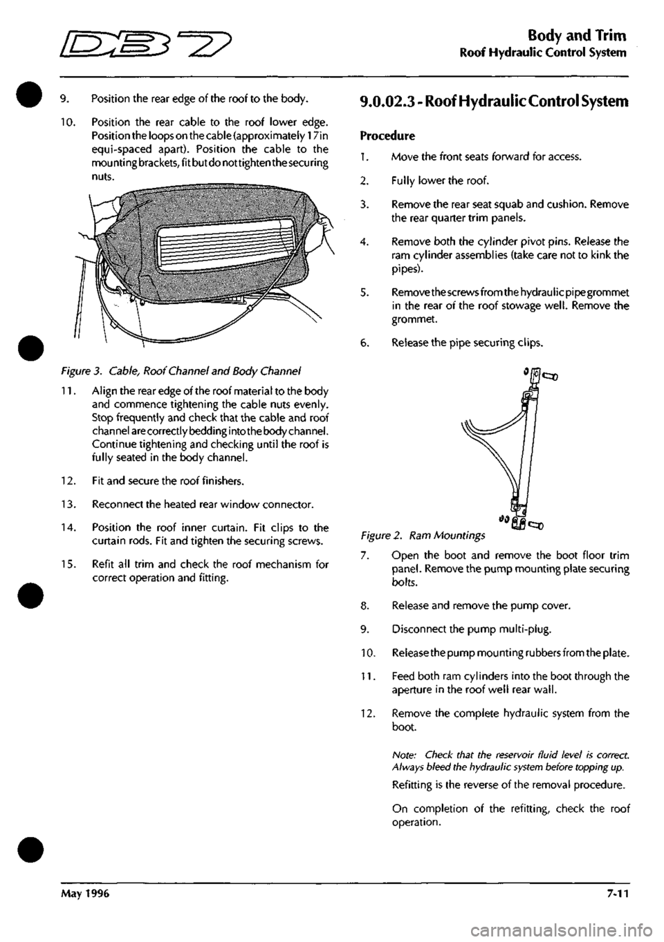
Position the rear cable to the roof lower edge.
Position the loops on the cable (approximately 17in
equi-spaced apart). Position the cable to the
mou nti ng
brackets,
fit but do not tighten the
secu
ring
nuts.
Figure 3. Cable, Roof Channel and Body Channel
11.
Align the rear edge of the roof material to the body
and commence tightening the cable nuts evenly.
Stop frequently and check that the cable and roof
channel
are
correctly bedding into the body channel.
Continue tightening and checking until the roof is
fully seated in the body channel.
12.
Fit and secure the roof finishers.
13.
Reconnect the heated rear window connector.
14.
Position the roof inner curtain. Fit clips to the
curtain rods. Fit and tighten the securing screws.
15.
Refit all trim and check the roof mechanism for
correct operation and fitting.
9.0.02.3 - Roof Hydraulic
Control
System
Procedure
1.
Move the front seats forward for access.
Fully lower the roof.
2.
3.
4.
6.
Remove the rear seat squab and cushion. Remove
the rear quarter trim panels.
Remove both the cylinder pivot pins. Release the
ram cylinder assemblies (take care not to kink the
pipes).
Remove the screws from the hydraulicpipegrommet
in the rear of the roof stowage
well.
Remove the
grommet.
Release the pipe securing clips.
Figure 2. Ram Mountings
7. Open the boot and remove the boot floor trim
panel.
Remove the pump mounting plate securing
bolts.
8. Release and remove the pump cover.
9. Disconnect the pump multi-plug.
10.
Releasethe pump mounting rubbers from the plate.
11.
Feed both ram cylinders into the boot through the
aperture in the roof well rear
wall.
12.
Remove the complete hydraulic system from the
boot.
Note: Check that the reservoir fluid level is correct.
Always bleed the hydraulic
system
before topping up.
Refitting is the reverse of the removal procedure.
On completion of the refitting, check the roof
operation.
May 1996 7-11
Page 268 of 421
•=2?
Body and Trim
Rear Quarter Window Renewal
9.1.01.1 -
Rear
Quarter Window Renewal
Procedure
1.
Move the front seat forward to gain access.
2.
Switch on the ignition, release the roof locking
latches and lower the roof to approximately the
midway position. Switch off the ignition.
3. Remove the rear seat squab and cushion. Remove
the rear quarter trim panel.
4.
Remove the roof cylinder support bracket securing
bolts.
5. Support the roof, removethecylindertoroofsecuring
bolt. Remove the cylinder bracket.
6. Disconnectthecylinderfromthepivotand carefully
lower the roof.
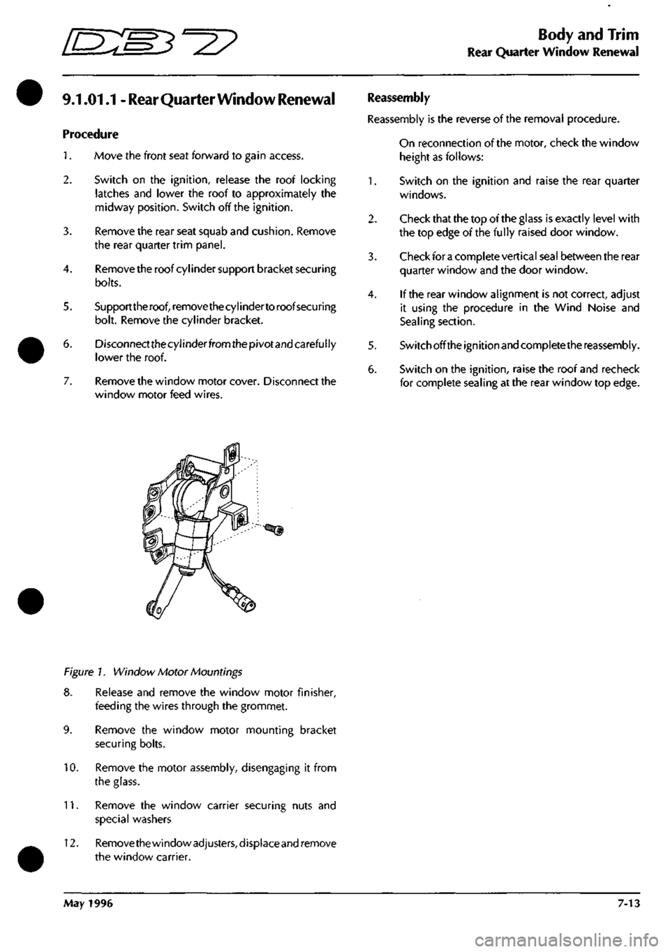
7. Remove the window motor cover. Disconnect the
window motor feed wires.
Reassembly
Reassembly is the reverse of the removal procedure.
On reconnection of the motor, check the window
height as follows:
1.
Switch on the ignition and raise the rear quarter
windows.
2.
Check that the top of the glass is exactly level with
the top edge of the fully raised door window.
3. Check for
a
complete vertical seal between the rear
quarter window and the door window.
4.
If the rear window alignment is not correct, adjust
it using the procedure in the Wind Noise and
Sealing section.
5. Switch off the ignition and complete the reassembly.
6. Switch on the ignition, raise the roof and recheck
for complete sealing at the rear window top edge.
Figure 1. Window Motor Mountings
8. Release and remove the window motor finisher,
feeding the wires through the grommet.
9. Remove the window motor mounting bracket
securing bolts.
10.
Remove the motor assembly, disengaging it from
the glass.
11.
Remove the window carrier securing nuts and
special washers
12.
Remove the window
adjusters,
d isplace and remove
the window carrier.
May 1996 7-13
Page 270 of 421
^^7
Body and Trim
Rear Quarter Window Lift Motor
9.1.01.4 - Rear Quarter Window Lift
Motor - Left Hand
Procedure
1.
Move the front seat forward to gain access.
2.
Switch on the ignition, release the roof locking
latches and lower the roof. Switch off the ignition.
Remove the rear seat squab and cushion. Remove
the rear quarter trim panel.
Disconnect the window motor feed wires.
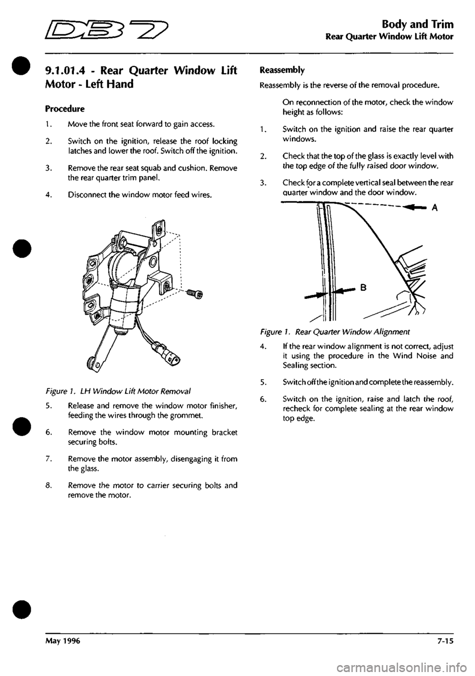
Figure 1. LH Window Lift Motor Removal
5. Release and remove the window motor finisher,
feeding the wires through the grommet.
6. Remove the window motor mounting bracket
securing bolts.
7. Remove the motor assembly, disengaging it from
the glass.
8. Remove the motor to carrier securing bolts and
remove the motor.
Reassembly
Reassembly is the reverse of the removal procedure.
On reconnection of the motor, check the window
height as follows:
1.
2.
Switch on the ignition and raise the rear quarter
windows.
Check that the top of the glass is exactly level with
the top edge of the fully raised door window.
Check for
a
complete vertical seal between the rear
quarter window and the door window.
Figure 1. Rear Quarter Window Alignment
4.
If the rear window alignment is not correct, adjust
it using the procedure in the Wind Noise and
Sealing section.
5. Switch off the ignition and complete the reassembly.
6. Switch on the ignition, raise and latch the roof,
recheck for complete sealing at the rear window
top edge.
May 1996 7-15
Page 271 of 421
Body and Trim
Rear Quarter Window Lift Motor '^^
9.1.01.5 - Rear Quarter Window Lift
Motor - Right Hand
Procedure
1.
Move the front seat forward to gain access.
2.
Switch on the ignition, release the roof locking
latches and lower the roof. Switch off the ignition.
3. Remove the rear seat squab and cushion. Remove
the rear quarter trim panel.
4.
Disconnect the window motor feed wires.
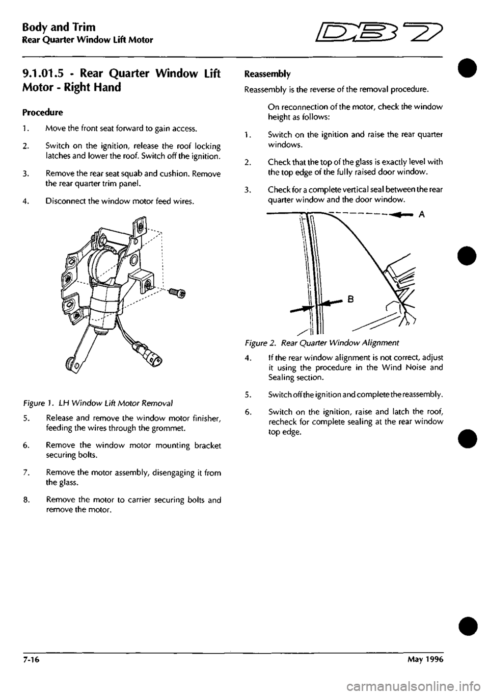
Figure 1. LH Window Lift Motor Removal
5. Release and remove the window motor finisher,
feeding the wires through the grommet.
6. Remove the window motor mounting bracket
securing bolts.
7. Remove the motor assembly, disengaging it from
the glass.
8. Remove the motor to carrier securing bolts and
remove the motor.
Reassembly
Reassembly is the reverse of the removal procedure.
On reconnection of the motor, check the window
height as follows:
1.
Switch on the ignition and raise the rear quarter
windows.
2.
Check that the top of the glass is exactly level with
the top edge of the fully raised door window.
3. Check for a complete vertical seal between the rear
quarter window and the door window.
A
Figure 2. Rear Quarter Window Alignment
4. If the rear window alignment is not correct, adjust
it using the procedure in the Wind Noise and
Sealing section.
5. Switch offthe ignition and complete the reassembly.
6. Switch on the ignition, raise and latch the roof,
recheck for complete sealing at the rear window
top edge.
7-16 May 1996
Page 273 of 421
Body and Trim
Roof Seals - Adjustment
9.2.01.6 - Roof
Seals
- Adjustment
Seal adjustment is done in two stages. First stage -
lateral adjustment, and second stage - outward
adjustment. Seals are packed out using selected
packing strips.
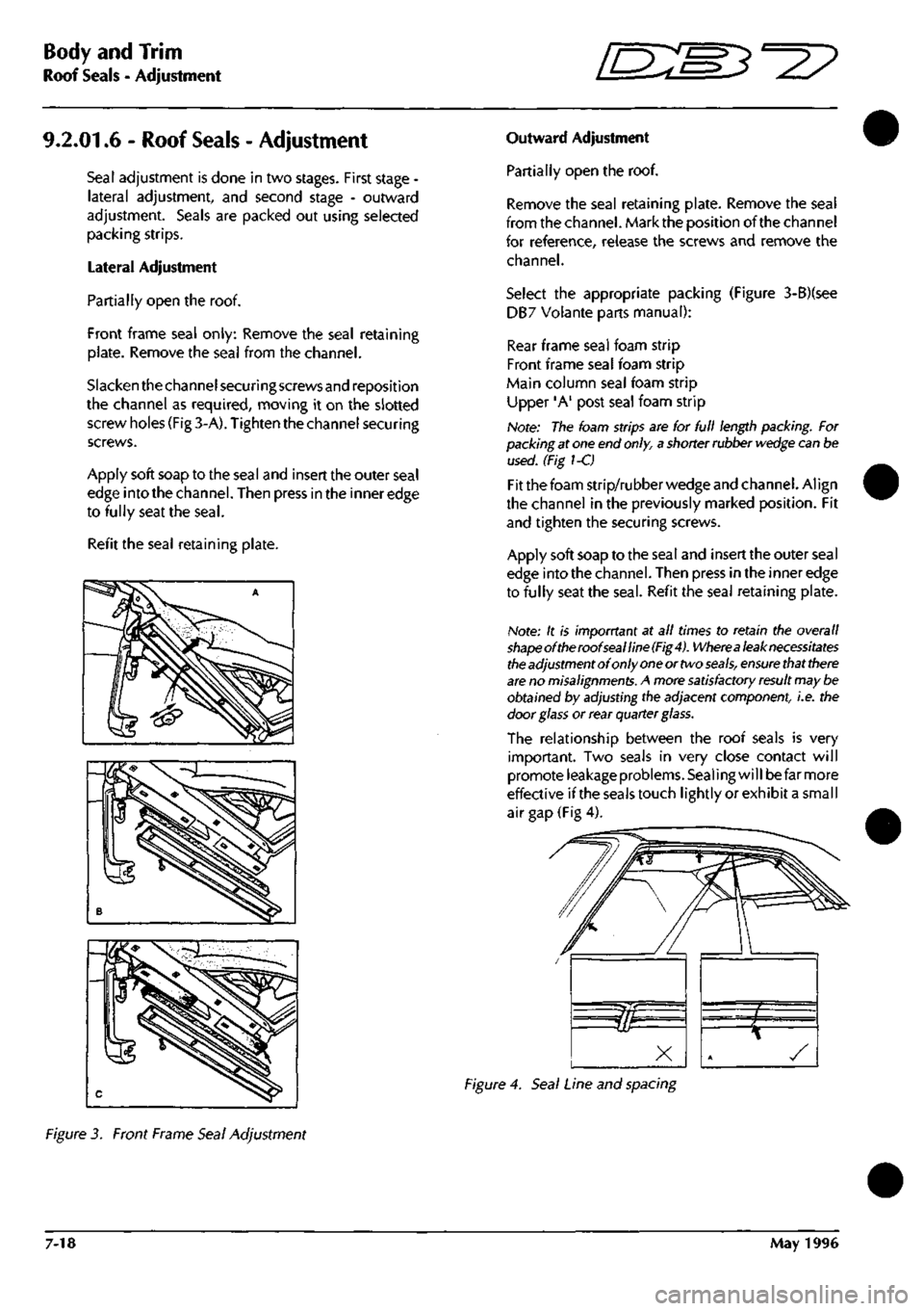
Lateral Adjustment
Partially open the roof.
Front frame seal only: Remove the seal retaining
plate.
Remove the seal from the channel.
Slacken the channel securing screws and reposition
the channel as required, moving it on the slotted
screw holes (Fig 3-A). Tighten the channel securing
screws.
Apply soft soap to the seal and insert the outer seal
edge into the channel. Then press in the inner edge
to fully seat the
seal.
Refit the seal retaining plate.
Outward Adjustment
Partially open the roof.
Remove the seal retaining plate. Remove the seal
from the channel. Mark the position of the channel
for reference, release the screws and remove the
channel.
Select the appropriate packing (Figure 3-B)(see
DB7 Volante parts manual):
Rear frame seal foam strip
Front frame seal foam strip
Main column seal foam strip
Upper 'A' post seal foam strip
Note: The foam strips are for full length packing. For
packing at one end
only,
a shorter rubber
wedge
can be
used. (Fig 1-C)
Fit the foam strip/rubber wedge and channel. Align
the channel in the previously marked position. Fit
and tighten the securing screws.
Apply soft soap to the seal and insert the outer seal
edge into the channel. Then press in the inner edge
to fully seat the
seal.
Refit the seal retaining plate.
Note: It is imporrtant at all times to retain the overall
shapeoftheroofsealline(Fig4).
Wherea
leak necessitates
the
adjustment of only
one
or two
seals,
ensure
that
there
are
no
misalignments.
A more
satisfactory result
may be
obtained by adjusting the adjacent component, i.e. the
door
glass
or rear quarter glass.
The relationship between the roof seals is very
important. Two seals in very close contact will
promote leakage problems. Sealing will be far more
effective ifthe seals touch lightly or exhibit a small
air gap (Fig 4).
Figure 4. Seal Line and spacing
Figure 3. Front Frame Seal Adjustment
7-18 May 1996